warning light Seat Toledo 2017 Repair Manual
[x] Cancel search | Manufacturer: SEAT, Model Year: 2017, Model line: Toledo, Model: Seat Toledo 2017Pages: 248, PDF Size: 5.86 MB
Page 186 of 248
Operation
– Shif t
t
o neutral.
– Release the clutch pedal.
Automatic
engine start up (Start phase)
– Press the clutch.
Switc
hing the Start-Stop system on and off
The Start-Stop system can be switched on
and off by pressing the button
››› Fig. 192.
The warning lamp in the button will light up
when the system is switched off.
If the vehicle is in Stop phase when the but-
ton is pressed, the engine will start immedi-
ately.
The Start-Stop system works under complex
driving conditions that are difficult to detect
without specialist technology. The set of nec-
essary conditions for the correct operating of
the Start-Stop system are indicated below.
Conditions for automatic engine shut down
(Stop phase) ● Selector lever in neutral.
● Clutch pedal not pressed.
● Driver with seat belt fastened.
● Driver door closed.
● The bonnet closed.
● Vehicle stationary. ●
The factor
y-fitted towing bracket is not elec-
trically connected to a trailer.
● Engine at operating temperature.
● Vehicle's battery sufficiently charged.
● Vehicle not on a very steep slope
● Engine speed below 1,200 rpm.
● Vehicle battery temperature is neither too
high nor too low
.
● Sufficient brake system pressure.
● Difference between outside temperature
and set interior t
emperature not too great
● Vehicle speed since the last time the en-
gine star
ted was above 3 km/h (2 mph).
● Particulate filter not being cleaned
›››
page 168.
● Front wheels not overly turned (steering
wheel turned l
ess than three quarters of a
turn)
Conditions for engine start up (Start phase)
● Clutch pedal pressed.
● Max./min. temperature set.
● Windscreen defrost function switched on.
● High blower speed.
● Start-Stop button pressed. Conditions for automatic engine start up
without driv
er involvement
● Vehicle moving at a speed of over 3 km/h
(2 mph).
● Difference between outside temperature
and interior temper
ature is too great
● Vehicle's battery insufficiently charged.
● Insufficient brake system pressure.
If the driver se
at belt is unfastened for more
than 30 seconds in Stop phase, the engine
must be started using the ignition key.
Please observe the messages on the general
instrument panel display.
Warnings on the instrument panel display
(valid for vehicles not fitted with an informa-
tive display)
FAULT: Start-StopFault in the Start-Stop sys-
tem
START-STOP IMPOSSI-
BLEEngine cannot be auto-
matically shut down
START-STOP ACTIVEAutomatic engine shut
down (Stop phase)
SWITCH OFF IGNITIONSwitch the ignition off
START MANUALLYStart the engine manually WARNING
● If the en gine i
s switched off, neither the
brake servo nor the power steering will work. 184
Page 187 of 248
Driver assistance systems
●
Do not mo v
e the vehicle when the engine is
switched off. CAUTION
Switch off the Start-Stop system ›
››
page 169
before driving through a pool of water on the
road. Note
● The batt er
y temperature may reflect
changes in outside temperature after several
hours. If the vehicle has been stopped out-
side at temperatures below zero or in direct
sunlight, for example, the battery tempera-
ture may take several hours to reach the val-
ues required for the correct operating of the
Start-Stop system.
● If the Climatronic system is operating auto-
matica
lly, this could impair automatic engine
shut down under certain conditions. Fatigue detection (break rec-
ommend
ation)*
Intr oduction The Fatigue detection informs the driver
when their driv
in
g beh
aviour shows signs of
fatigue. WARNING
Do not let the comfort afforded by the Fatigue
detection sy s
tem tempt you into taking any
risks when driving. Take regular breaks, suffi-
cient in length when making long journeys.
● The driver always assumes the responsibil-
ity of driv
ing to their full capacity.
● Never drive if you are tired.
● The system does not detect the tiredness of
the driver in al
l circumstances. Consult the in-
formation in the section ››› page 186, System
limitations.
● In some situations, the system may incor-
rectly int
erpret an intended driving manoeu-
vre as driver tiredness.
● No warning is given in the event of the ef-
fect c
alled microsleep!
● Please observe the indications on the in-
strument p
anel and act as is necessary. Note
● Fatigue det ection h
as been developed for
driving on motorways and well paved roads
only.
● If there is a fault in the system, have it
check
ed by a specialised workshop. Function and operation
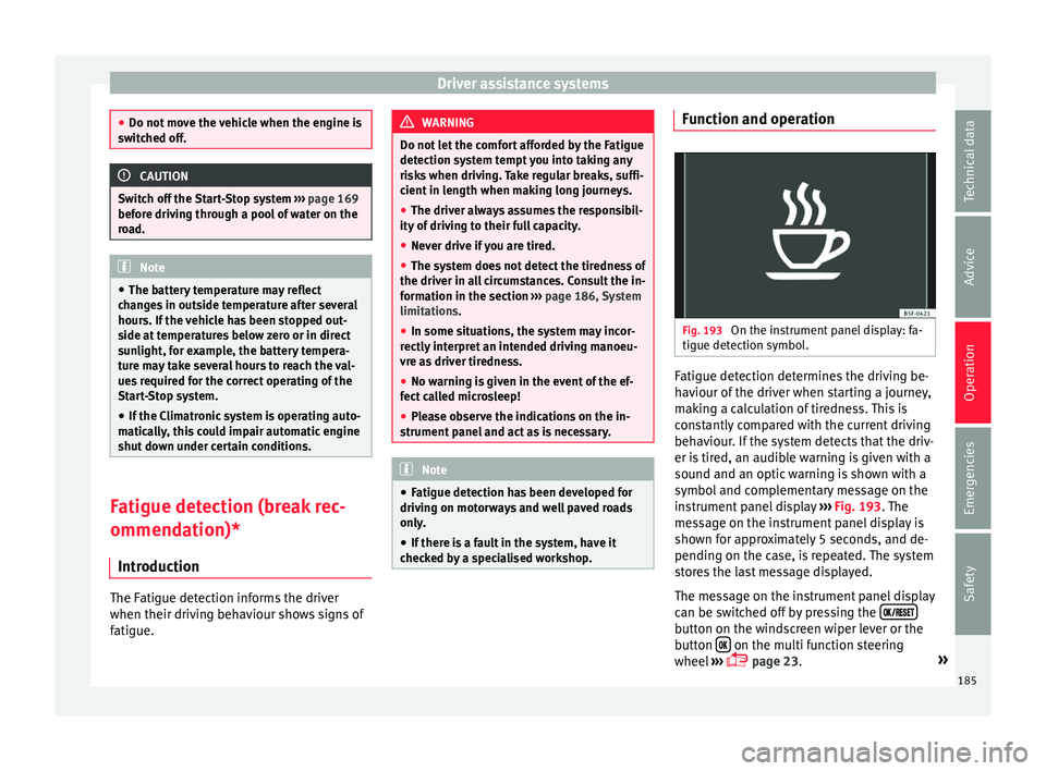
Fig. 193
On the instrument panel display: fa-
tigue det ection symbo
l
. Fatigue detection determines the driving be-
h
av
iour of
the driver when starting a journey,
making a calculation of tiredness. This is
constantly compared with the current driving
behaviour. If the system detects that the driv-
er is tired, an audible warning is given with a
sound and an optic warning is shown with a
symbol and complementary message on the
instrument panel display ››› Fig. 193. The
message on the instrument panel display is
shown for approximately 5 seconds, and de-
pending on the case, is repeated. The system
stores the last message displayed.
The message on the instrument panel display
can be switched off by pressing the button on the windscreen wiper lever or the
b
utt
on on the multi function steering
wheel
›
›
› page 23. »
185
Technical data
Advice
Operation
Emergencies
Safety
Page 189 of 248
Towing bracket device
Trailer weight Trailer weight
The comb
ined
vehicle and trailer must be
balanced. To do so use the maximum permit-
ted towing bracket load. An insufficient
weight exerted by the trailer drawbar on the
ball joint of the towing bracket will have a
negative impact upon the response of the ve-
hicle-trailer assembly on the road.
Weight distribution
Distribute loads in the trailer so that heavy
objects are as near to the axle as possible.
Ensure that the objects do not move.
If the towing vehicle is empty and the trailer
loaded then the load distribution is incorrect.
However, if these conditions cannot be avoi-
ded, drive very slowly.
Tyre pressure values
Correct the tyre pressure in your vehicle to
“total load” ›››
page 218, Service life of
tyres.
Trailer weight
Never exceed the authorised trailer weight
under any circumstances ›››
page 223, Tech-
nical specifications .
The trailer weights listed are only applicable
for altitudes up to 1000 m above sea level.
Due to lower air density, engine power de- creases depending on the increase in alti-
tude, thi
s
also reduces climbing ability,
which requires a reduction of the weight of
the vehicle with a trailer by 10% for every
1000 m increase in altitude. The weight of
the assembly is calculated by adding the ve-
hicle weight (loaded) to the trailer weight
(loaded). Always drive with special care when
towing a trailer.
The towed load and support load information
that is displayed on the towing bracket man-
ufacturers label are only values for the verifi-
cation of the device. The correct figures for
your specific vehicle, which are usually lower
than these figures, are given in the documen-
tation of your vehicle. WARNING
● Exc eedin
g the maximum established load
per axle and the maximum towing bracket
load in addition to the maximum permitted
load or the load of the vehicle + trailer as-
sembly can cause accidents and serious inju-
ries.
● A sliding load can considerably affect the
stab
ility and safety of the vehicle + trailer as-
sembly, resulting in accidents and serious in-
juries. Driving with a trailer
Exterior mirrors
Check
whether
you can see enough of the
road behind the trailer with the standard rear
vision mirrors. If this is not the case, you
should have additional exterior mirrors fitted.
Observe the relevant statutory requirements
of the country you are in.
Headlights
Before starting a journey, also check the
headlight beam settings with the trailer
hitched up. Adjust the headlight range set-
tings if necessary ›››
page 122, Headlight
range control.
Driving speed
For your own safety do not drive faster than
the maximum permitted speed indicated on
the trailer.
At all times, immediately reduce speed if you
detect the slightest swaying movement of the
trailer. Never try to “return the trailer to a
straight position” by accelerating.
Brakes
Brake in due course! If the trailer has an over-
run brake, apply the brakes gently at first and
then, firmly. This will prevent the jerking that
can be caused by locking of trailer wheels.
Change to a lower gear in good time before »
187
Technical data
Advice
Operation
Emergencies
Safety
Page 190 of 248
Operation
descending a slope in order to take advant-
ag e of
the en
gine brake.
The trailer is incorporated into the vehicle's
anti-theft alarm system:
● When the vehicle has a factory-fitted anti-
theft al
arm and a towing bracket.
● When the trailer is electrically connected to
the vehic
le via the towing bracket socket.
● When the vehicle electrical device and the
tow
ing bracket are operational.
● When the vehicle is locked and the vehi-
cle's
anti-theft alarm device is activated.
Once the electrical connection is interrupted
with the vehicle trailer locked, the alarm
sounds.
Always switch off the vehicle anti-theft alarm
device before connecting or disconnecting a
trailer. The vehicle anti-theft alarm device
could cause the alarm to sound ››› page 116,
Anti-theft alarm*.
Engine overheating
In the event that the coolant temperature
gauge needle moves to the right section of
the scale or to the red area, immediately re-
duce speed. If the control lamp flashes on
the general instrument panel, stop the vehi-
cle and switch off the engine. Wait several
minutes and check the coolant level in the
tank ››› page 210. Please observe the following indications
›››
page 210, Control lamp .
The coolant temperature can be reduced by
switching on the heating. WARNING
● Adjus t
your speed to suit the road and traf-
fic conditions.
● An electrical installation that is connected
incorrectly
or by non-specialised personnel
can prevent the connection of the current to
the trailer and cause faults in the operation of
the electrical system throughout the entire
vehicle, leading to accidents and serious in-
jury.
● All electrical work must be carried out only
by s
pecialised services.
● Never directly connect the trailer electrical
device t
o the electrical sockets of the reverse
driving lights or other sources of electrical
current. CAUTION
● Av oid c
orners, and sudden and sharp brak-
ing.
● Once the trailing arm has been removed,
plac
e the corresponding cover on the hole of
the fastening point. This prevents dirt from
entering the hole – see the trailer system as-
sembly manual. Note
● In the event of
frequent journeys with a
trailer, we recommend also having the vehi-
cle inspected in between the service inter-
vals.
● When connecting and disconnecting the
trail
er, the handbrake must be applied.
● For technical reasons, trailers with LED re-
verse light
s cannot be incorporated into the
vehicle anti-theft alarm system. Towing bracket device
Intr oduction If the vehicle is equipped with a towing
br
ac
k
et device from the factory or is a genu-
ine SEAT accessory, it meets all national tech-
nical and legal requirements for towing.
Your vehicle is fitted with a 13-pin power
socket for the electrical connection between
the trailer and the vehicle. If the trailer is
equipped with a 7-pin connector, you can
use the corresponding adaptor, which is
available as a genuine SEAT accessory.
The towing device has a maximum vertical
load of 50 kg.
188
Page 197 of 248
Care and maintenance
●
The modification of the s
uspension of the
vehicle wheels, including the use of non-per-
mitted combinations of tyres and rims can al-
ter the operation of the airbag system and in-
crease the risk of serious or fatal injuries in
an accident.
● During all jobs on the airbag system, in ad-
dition to the remo
val and fitting of parts of
the system in the course of other repair jobs,
parts of the airbag system can be damaged.
Therefore in the event of an accident, this
may cause the airbags to activate incorrectly
or not activate at all. Radio and aerial reception
In vehicles factory-fitted with an audio or
n
av
ig
ation system, the aerial may be instal-
led in different places:
● inside the rear window next to the heating
elements,
● on the roof
of the vehicle.
Care and cleaning Introduction Regular and suitable care helps to
m
aint ain
the u
seful life of your vehicle. This may also
be one of the requirements for upholding any warranty claims in the event of corrosion or
paint def
ects.
We recommend you use cleaning products
from the SEAT Original Accessories pro-
gramme available in SEAT dealers. Please fol-
low the instructions for use on the packag-
ing. WARNING
● Cle
aning products and other materials used
for car care can damage the health if mis-
used.
● Always keep car care materials in a safe
plac
e out of the reach of children. Risk of poi-
soning!
● When washing the car during the winter
season: Moi
sture and ice on the brakes may
affect braking efficiency. Risk of accident!
● The ignition must always be switched off
when the car is
washed. Risk of accident!
● Do not clean the underside of the car or in-
side the wheel ar
ches without protecting your
hands and arms. You may cut yourself on
sharp metal parts!
● Perfumes and air fresheners inside the ve-
hicle m
ay be harmful to health at high tem-
peratures in the interior. CAUTION
● Check the c
olour-fastness of your clothing
to avoid damaging or visibly staining the fab-
ric (leather), upholstery and fabric trim. ●
Cle
aning products containing solvents may
damage the material being cleaned.
● Do not wash the vehicle in direct sunlight.
Risk of
damage to paintwork.
● If washing the vehicle with a hose in win-
ter, do not
direct the jet of water directly at
the locks or at the door seals or bonnet. Risk
of freezing.
● Do not use sponges for removing insects or
abras
ive household sponges, etc. on painted
surfaces. Risk of damage to the painted sur-
face!
● Do not put stickers on the inner side of the
rear w
indow in areas where heating elements
or the aerial are located. This could cause
damage and, in the case of the aerial, radio
and navigation system reception faults.
● Do not clean the inside of the window with
sharp ob
jects or corrosive or acidic cleaning
products. Risk of damaging the heating ele-
ments or the aerial.
● Do not attach any fragrance or air freshener
to the da
sh panel. Risk of damage to the
dash panel!
● To avoid damaging the parking aid system
sensors, s
pray them only briefly at a mini-
mum distance of 10 cm when cleaning the ve-
hicle with a high-pressure or steam cleaner.
● Do not clean the roof panel with a brush.
Risk of
damage to the panel surface! » 195
Technical data
Advice
Operation
Emergencies
Safety
Page 201 of 248
Care and maintenance
Wheels Wheel trims
If
y
ou wash the vehicle regularly, you should
also thoroughly wash the wheel trim. Regu-
larly remove any brake dust and road salt
from the wheels, otherwise the wheel materi-
al could be damaged. Repair any damage to
the wheel paintwork immediately.
Alloy wheels
After thorough washing, treat the wheels
with a protective product for alloy wheels. Do
not use abrasive products to care for the
wheels. WARNING
Moisture, ice and road salt may affect braking
efficiency . Ri
sk of accident! CAUTION
Heavy dirt on the wheels could lead to their
mis a
lignment. This could result in vibrations
being transmitted to the steering wheel that
under certain conditions may cause prema-
ture steering wear. This dirt must be re-
moved. Note
We recommend you leave paint damage re-
pair s
to a SEAT Authorised Service. Vehicle underbody protection
The underside of the vehicle is coated to per-
manently
pr
otect it from chemical and me-
chanical agents.
Given that damage to the protective coating
during driving cannot be completely ruled
out, we recommend you check the condition
of the protective coating on the underbody
and suspension at regular intervals, prefera-
bly before the start and end of the coldest
season of the year.
Authorised SEAT dealers have suitable spe-
cial products and the necessary facilities and
are aware of the techniques required for their
application. We therefore recommend all
touch-up work or additional anti-corrosion
measures be performed by an authorised
SEAT dealer. WARNING
Do not apply underseal or anti-corrosion
co atin
gs to the exhaust pipes, catalytic con-
verter, particulate filter or heat shields on the
exhaust system. Once the engine has
reached operating temperature, these sub-
stances could catch fire. Risk of fire! Cavity waxing
All cavities on the vehicle exposed to corro-
sion ar
e perm
anently factory-protected by a
wax solution .
This wax solution does not need to be
checked or touched up. Should wax run out
of the cavities at high ambient temperatures,
remove it using a plastic scraper and clean
away any stains using lighter fluid. WARNING
Note the regulations concerning safety and
env ir
onmental protection if you use lighter
fluid to remove the wax. Risk of fire! Leatherette and upholstery
Leatherette can be cleaned with a damp
c
loth. If
thi
s is not sufficient, these parts
should only be cleaned with solvent-free
plastic care and cleaning products .
Textile covers and trim parts on doors, boot
lid, etc. can be cleaned with special deter-
gents, e.g. dry foam. A soft sponge or brush
or a micro-fibre cloth for normal cleaning can
be used. Use special products to clean the
headliner. »
199
Technical data
Advice
Operation
Emergencies
Safety
Page 204 of 248
Advice
– Chec k
th
at the fuel flap is correctly closed.
Vehicles with a keyless fuel cap (the side
flap will unlock using the central locking sys-
tem)
– Once the vehicle has been unlocked using
the central
locking button, press the fuel
flap in the direction of the arrow 1›››
Fig. 202.
– Open the cover in the direction indicated
by
the arr
ow 2 .
– Unscrew the tank cap anti-clockwise and
pl
ac
e it on top of the tank flap ››› Fig. 202
.
– Insert the pump nozzle into the fuel feed
tube as
far as it will go.
The fuel tank is full as soon as the automatic
filler nozzle cuts out ››› .
– Remove the pump nozzle from the fuel feed
tube and p
l
ace it back on the pump.
– Screw the tank cap clockwise until it clicks
into pl
ace.
– Close the tank flap. Make sure you hear it
click
into place.
– Check that the fuel flap is properly closed. WARNING
Observe all relevant statutory regulations on
tran s
porting spare fuel canisters. For safety reasons, we do not recommend carrying a
sp
ar
e canister in the vehicle. The canister
could be damaged in an accident and fuel
may leak. Risk of fire! CAUTION
● Sw itc
h off the auxiliary heater (heater and
independent heater) before filling the tank.
● The fuel tank is full as soon as the automat-
ic fil
ler nozzle cuts out. Do not continue fill-
ing, as this will fill the expansion chamber.
● Never completely empty the tank! An irreg-
ular f
uel supply can cause ignition faults,
which can result in damage to a substantial
amount of engine parts and the exhaust sys-
tem.
● If any fuel is spilt onto the paintwork of the
vehicl
e, it should be removed immediately.
Risk of damage to paintwork! Note
There is no emergency mechanism for the
manua l
release of the fuel tank flap. If neces-
sary, request assistance from specialised per-
sonnel. Note
The fuel tank capacity is around 55 litres, of
which 7 litr e
s are the reserve. Types of petrol
The correct grade of petrol is listed inside the
fuel
t
ank flap.
The vehicle is equipped with a catalytic con-
verter and must only be run on unleaded pet-
rol. The petrol must comply with European
Standard EN 228 or German standard DIN
51626-1 and must be unleaded. You can re-
fuel with a maximum ethanol proportion of
10 % (E10). The types of petrol are differenti-
ated by their octane rating (RON).
The following titles appear on the corre-
sponding adhesive on the fuel tank flap:
Super unleaded 95 octane or normal 91 oc-
tane unleaded petrol
We recommend you use super 95 octane pet-
rol. If this is not available: normal 91 octane
petrol, with a slight decrease in power.
Super unleaded petrol with a minimum of 95
octanes
You should use super petrol with a minimum
of 95 octanes.
If super is not available, in an emergency you
may refuel with normal 91 octane petrol. In
this case only use moderate engine speeds
and a light throttle. Refuel with super as soon
as possible.
202
Page 211 of 248
Checking and refilling levels
Go to a technical service.
The c ontr
o
l lamp lights up yellow (insuf-
ficient oil level)
The informative display indicates:
Check the oil level!
Stop the vehicle, switch off the engine and
check the engine oil level ››› page 209
If the bonnet remains open for more than 30
seconds, the warning lamp switches off. If
the engine oil is not refilled, the warning
lamp illuminates again after 100 km (62
miles).
The control lamp flashes yellow (oil level
sensor faulty)
The informative display indicates:
Oil sensor. Workshop!
If the engine oil level sensor is faulty, The
warning lamp flashes various times after
the ignition is switched on and an audible
warning is given.
Go to a technical service. Checking engine oil level
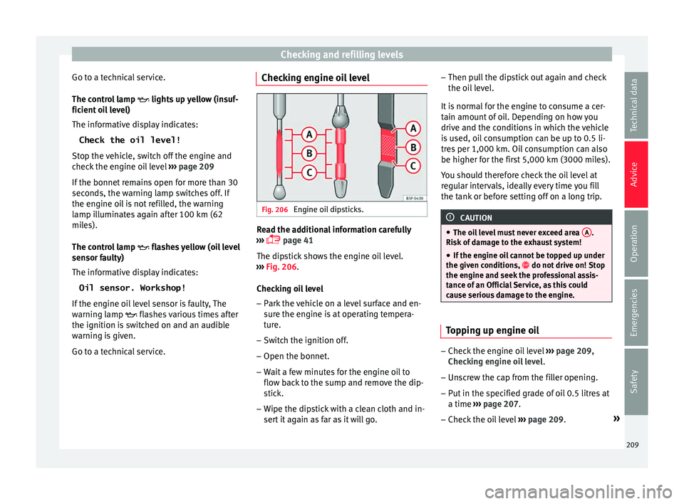
Fig. 206
Engine oil dipsticks. Read the additional information carefully
› ›
›
page 41
The dipstick shows the engine oil level.
››› Fig. 206.
Checking oil level – Park the vehicle on a level surface and en-
sure the en
gine is at operating tempera-
ture.
– Switch the ignition off.
– Open the bonnet.
– Wait a few minutes for the engine oil to
flow bac
k to the sump and remove the dip-
stick.
– Wipe the dipstick with a clean cloth and in-
sert it
again as far as it will go. –
Then pul
l the dipstick out again and check
the oil level.
It is normal for the engine to consume a cer-
tain amount of oil. Depending on how you
drive and the conditions in which the vehicle
is used, oil consumption can be up to 0.5 li-
tres per 1,000 km. Oil consumption can also
be higher for the first 5,000 km (3000 miles).
You should therefore check the oil level at
regular intervals, ideally every time you fill
the tank or before setting off on a long trip. CAUTION
● The oil l
evel must never exceed area A .
Risk of
damage to the exhaust system!
● If the engine oil cannot be topped up under
the given condition
s, do not drive on! Stop
the engine and seek the professional assis-
tance of an Official Service, as this could
cause serious damage to the engine. Topping up engine oil
–
Check the engine oil level ››
›
page 209,
Checking engine oil level .
– Unscrew the cap from the filler opening.
– Put in the specified grade of oil 0.5 litres at
a time ›››
page 207.
– Check the oil level ›››
page 209. »
209
Technical data
Advice
Operation
Emergencies
Safety
Page 213 of 248
Checking and refilling levels
– Re
a
d off the coolant level on coolant ex-
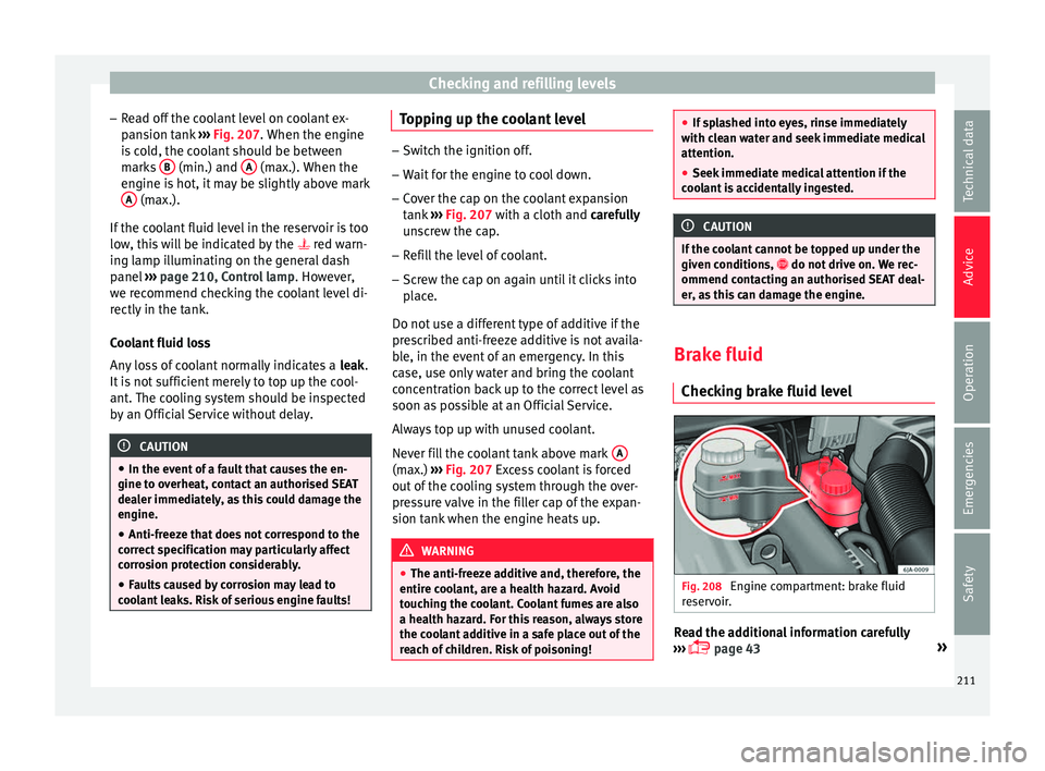
pansion tank ››› Fig. 207. When the engine
is cold, the coolant should be between marks B (min.) and
A (max.). When the
en gine i
s
hot, it may be slightly above mark
A (max.).
If the c
oo
lant fluid level in the reservoir is too
low, this will be indicated by the red warn-
ing lamp illuminating on the general dash
panel ››› page 210, Control lamp . However,
we recommend checking the coolant level di-
rectly in the tank.
Coolant fluid loss
Any loss of coolant normally indicates a leak.
It is not sufficient merely to top up the cool-
ant. The cooling system should be inspected
by an Official Service without delay. CAUTION
● In the event of
a fault that causes the en-
gine to overheat, contact an authorised SEAT
dealer immediately, as this could damage the
engine.
● Anti-freeze that does not correspond to the
correct
specification may particularly affect
corrosion protection considerably.
● Faults caused by corrosion may lead to
cool
ant leaks. Risk of serious engine faults! Topping up the coolant level
–
Switch the ignition off.
– Wait for the engine to cool down.
– Cover the cap on the coolant expansion
tank ›
›› Fig. 207 with a cloth and carefully
unscrew the cap.
– Refill the level of coolant.
– Screw the cap on again until it clicks into
plac
e.
Do not use a different type of additive if the
prescribed anti-freeze additive is not availa-
ble, in the event of an emergency. In this
case, use only water and bring the coolant
concentration back up to the correct level as
soon as possible at an Official Service.
Always top up with unused coolant.
Never fill the coolant tank above mark A (max.)
››
›
Fig. 207 Excess coolant is forced
out of the cooling system through the over-
pressure valve in the filler cap of the expan-
sion tank when the engine heats up. WARNING
● The anti-freez e a
dditive and, therefore, the
entire coolant, are a health hazard. Avoid
touching the coolant. Coolant fumes are also
a health hazard. For this reason, always store
the coolant additive in a safe place out of the
reach of children. Risk of poisoning! ●
If s p
lashed into eyes, rinse immediately
with clean water and seek immediate medical
attention.
● Seek immediate medical attention if the
cool
ant is accidentally ingested. CAUTION
If the coolant cannot be topped up under the
giv en c ondition
s, do not drive on. We rec-
ommend contacting an authorised SEAT deal-
er, as this can damage the engine. Brake fluid
Chec kin
g brake fluid level Fig. 208
Engine compartment: brake fluid
r e
ser
voir. Read the additional information carefully
› ›
›
page 43 »
211
Technical data
Advice
Operation
Emergencies
Safety
Page 214 of 248
Advice
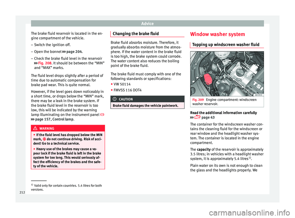
The brake fluid reservoir is located in the en-
gine c omp
ar
tment of the vehicle.
– Switch the ignition off.
– Open the bonnet ›››
page 204.
– Check the brake fluid level in the reservoir
›››
Fig. 208. It should be between the “MIN”
and “MAX” marks.
The fluid level drops slightly after a period of
time due to automatic compensation for
brake pad wear. This is quite normal.
However, if the level goes down noticeably in
a short time, or drops below the “MIN” mark,
there may be a leak in the brake system. If
the brake fluid level in the reservoir is too
low, this will be indicated by the warning
lamp illuminating on the instrument panel
››› page 157, Control lamp .WARNING
● If the fluid l ev
el has dropped below the MIN
mark, do not continue driving. Risk of acci-
dent! Go to a technical service.
● Heavy use of the brakes may cause a va-
pour lock if
the brake fluid is left in the brake
system for too long. This would seriously af-
fect the efficiency of the brakes and the safe-
ty of the vehicle. Changing the brake fluid
Brake fluid absorbs moisture. Therefore, it
gra
dual
ly absorbs moisture from the atmos-
phere. If the water content in the brake fluid
is too high, the brake system could corrode.
The water content also reduces the boiling
point of the brake fluid.
The brake fluid must comply with one of the
following standards or specifications:
● VW 50114
● FMVSS 116 DOT4 CAUTION
Brake fluid damages the vehicle paintwork. Window washer system
Top
pin
g up windscreen washer fluid Fig. 209
Engine compartment: windscreen
w a
sher r
eservoir. Read the additional information carefully
› ›
›
page 43
The container for the windscreen washer con-
tains the cleaning fluid for the windscreen or
rear window and the headlight washer sys-
tem. The container is located in the engine
compartment.
The capacity of the reservoir is approximately
3.5 litres; in vehicles with a headlight washer
system, it is approximately 5.4 litres 1)
.
Plain water on its own is not enough to clean
the glass and the headlights properly. We 1)
Valid only for certain countries. 5.4 litres for both
ver s
ions.
212