fuel cap Seat Toledo 2017 Owner's manual
[x] Cancel search | Manufacturer: SEAT, Model Year: 2017, Model line: Toledo, Model: Seat Toledo 2017Pages: 248, PDF Size: 5.86 MB
Page 42 of 248
The essentials
››› in General notes on page 146
››› page 148 Fluid Level control
Fi l
lin
g capacities
Capacities
Fuel tank55 litres, of which 7 litres act
as reserve.
Windscreen washer flu-
id container in version
without headlight wash-
er
3.5 litres
Windscreen washer flu-
id container in versions
with headlight washer5.4 litres Fuel
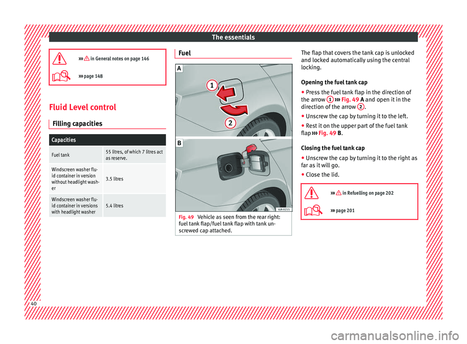
Fig. 49
Vehicle as seen from the rear right:
f uel
t
ank flap/fuel tank flap with tank un-
screwed cap attached. The flap that covers the tank cap is unlocked
and loc
k
ed aut
omatically using the central
locking.
Opening the fuel tank cap
● Press the fuel tank flap in the direction of
the arrow 1
› ››
Fig. 49
A and open it in the
direction of the arrow 2 .
● Unscrew the cap by turning it to the left.
● Rest it on the upper part of the fuel tank
fl ap
›
›
› Fig. 49 B.
Closing the fuel tank cap
● Unscrew the cap by turning it to the right as
far as
it will go.
● Close the lid.
››› in Refuelling on page 202
››› page 201 40
Page 44 of 248
The essentials
Engine oil specificationsService intervalEngine typeSpecification
Petrol engines with Set Service Intervals (dependent on
time/distance travelled)1.0l / 1.4lVW 504 00
1.6lVW 502 00 a)
Petrol engines with Flexible Service Intervals (LongLife)1.0l / 1.4lVW 508 00
VW 504 00b)
Diesel engines with Set Service and Flexible Service In-
tervalsc)With particulate filter (DPF)VW 507 00
a)
If the quality of the fuel available in the country does not fulfil the EN 228 (for petrol) and EN 590 (for diesel) standards.
b) Use of engine oil compliant with the VW 504 00 specification instead of VW 508 00 may have a slight negative effect on the vehicle’s exhaust gas values.
c) Only use recommended oils, otherwise you may damage the engine.
››› page 207 Coolant
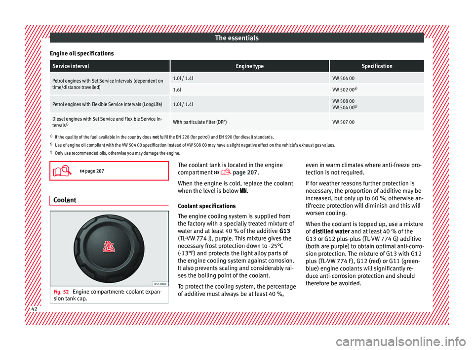
Fig. 52
Engine compartment: coolant expan-
s ion t
ank
cap. The coolant tank is located in the engine
c
omp
ar
tment ›››
page 207.
When the engine is cold, replace the coolant
when the level is below .
Coolant specifications
The engine cooling system is supplied from
the factory with a specially treated mixture of
water and at least 40 % of the additive G13
(TL-VW 774 J), purple. This mixture gives the
necessary frost protection down to -25°C
(-13°F) and protects the light alloy parts of
the engine cooling system against corrosion.
It also prevents scaling and considerably rai-
ses the boiling point of the coolant.
To protect the cooling system, the percentage
of additive must always be at least 40 %, even in warm climates where anti-freeze pro-
tection is
not required.
If for weather reasons further protection is
necessary, the proportion of additive may be
increased, but only up to 60 %; otherwise an-
tifreeze protection will diminish and this will
worsen cooling.
When the coolant is topped up, use a mixture
of distilled water and at least 40 % of the
G13 or G12 plus-plus (TL-VW 774 G) additive
(both are purple) to obtain optimal anti-corro-
sion protection. The mixture of G13 with G12
plus (TL-VW 774 F), G12 (red) or G11 (green-
blue) engine coolants will significantly re-
duce anti-corrosion protection and should
therefore be avoided. 42
Page 54 of 248
The essentials
Notes for the driver of the towing vehicle
● The tow rope must be taut before you drive
off .
● Rel
ease the clutch very carefully when start-
ing the v
ehicle (manual gearbox), or acceler-
ate gently (automatic gearbox).
Driving style
Towing requires some experience, especially
when using a tow rope. Both drivers should
realise how difficult it is to tow a vehicle. In-
experienced drivers should not attempt to
tow.
Do not pull too hard with the towing vehicle
and take care to avoid jerking the tow rope.
When towing on an unpaved road, there is al-
ways a risk of overloading and damaging the
anchorage points.
The towline anchorages are located under
the floor panel in the luggage compartment.
Switch on the ignition so that the turn sig-
nals, windscreen wipers and windscreen
washer can work. Ensure that the steering
wheel is unlocked and moves freely.
Place the gear lever in neutral on vehicles
with a manual gearbox. With an automatic
gearbox, place the lever in N.
To brake, press the brake pedal firmly. The
brake servo does not work when the engine
is switched off. The power steering only works when the igni-
tion is sw
itched on and the vehicle is moving,
provided that the battery is sufficiently charg-
ed. Otherwise, it will need more force.
Ensure that the tow rope remains taut at all
times.
››› page 79 Tow-starting
If the engine will not start, first try starting it
u
s
in
g the battery of another vehicle
››› page 52. You should only attempt to tow-
start a vehicle if charging the battery does
not work. This is done by leveraging wheel
movement.
When tow-starting a vehicle with a petrol en-
gine, do not tow it more than a short dis-
tance, otherwise unburned fuel can enter the
catalytic converter.
● Engage 2nd or 3rd gear before moving off.
● Press the clutch and hold the pedal down.
● Switch the ignition on.
● Once both vehicles are moving, release the
clutc
h.
● As soon as the engine has started, press
the clutc
h and move the gear lever to neutral. How to jump start
Jump lea
ds The jump lead must have a sufficient wire
cr
o
ss section.
If the engine fails to start because of a dis-
charged battery, the battery can be connec-
ted to the battery of another vehicle to start
the engine.
Both batteries need to have nominal voltage
of 12 V. The capacity (Ah) of the back-up bat-
tery should not be notably less than the
drained battery.
Jump leads must comply with standard DIN
72553 (see cable manufacturer's instruc-
tions). The wire cross section must be at least
25 mm 2
for petrol engines and at least
35 mm 2
for diesel engines.
Jump leads
Positive cable – usually red
Negative cable – usually black WARNING
● A flat b
attery can also freeze at tempera-
tures slightly below 0°C (+32°F). Do not at-
tempt to start the vehicle with a frozen bat-
tery. Risk of explosion! 52
Page 56 of 248
The essentials
Starting Star
t
the engine of the vehicle with the
boosting battery and let it run at idling
speed.
Start the engine of the vehicle with the
flat battery and wait for 2 or 3 minutes
until the engine is running.
Removing the jump leads Before you remove the jump leads,
switch off the dipped beam headlights if
they are switched on.
Turn on the heater blower and heated
rear window in the vehicle with the flat
battery. This helps minimise voltage
peaks which are generated when the
leads are disconnected.
When the engine is running, disconnect
the leads in reverse order to the details
given above.
Make sure the battery clamps have sufficient
metal-to-metal contact with the battery termi-
nals.
If the engine fails to start after about 10 sec-
onds, switch off the starter and try again after
about 1 minute. WARNING
● Ple a
se note the safety warnings referring to
working in the engine compartment
››› page 204. 7.
8.
9.
10.
11. ●
The batt er
y providing assistance must have
the same voltage as the flat battery (12V) and
approximately the same capacity (see imprint
on battery). Failure to comply could result in
an explosion.
● Never use jump leads when one of the bat-
teries
is frozen. Danger of explosion! Even af-
ter the battery has thawed, battery acid could
leak and cause chemical burns. If a battery
freezes, it should be replaced.
● Keep sparks, flames and lighted cigarettes
awa
y from batteries, danger of explosion.
Failure to comply could result in an explo-
sion.
● Observe the instructions provided by the
manufact
urer of the jump leads.
● Do not connect the negative cable from the
other vehic
le directly to the negative terminal
of the flat battery. The gas emitted from the
battery could be ignited by sparks. Danger of
explosion.
● Never attach the negative cable to fuel sys-
tem component
s or the brake lines in the oth-
er vehicle.
● The non-insulated parts of the battery
clamp
s must not be allowed to touch. The
jump lead attached to the positive battery
terminal must not touch metal parts of the ve-
hicle, this can cause a short circuit.
● Position the leads in such a way that they
cannot c
ome into contact with any moving
parts in the engine compartment.
● Do not lean on the batteries. This could re-
sult
in chemical burns. Note
The vehicles must not touch each other, oth-
erw i
se electricity could flow as soon as the
positive terminals are connected. Changing the windscreen wiper
bl
a
des
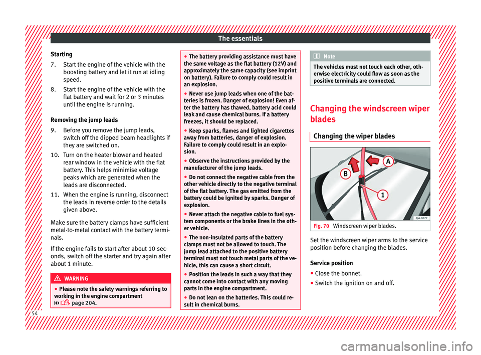
Changing the wiper blades Fig. 70
Windscreen wiper blades. Set the windscreen wiper arms to the service
po
s
ition bef
ore changing the blades.
Service position
● Close the bonnet.
● Switch the ignition on and off. 54
Page 102 of 248
Operation
Normal temperature
If in norm
al
operations, the diodes light up
until the central zone, it means that the en-
gine has reached operating temperature. At
high outside temperatures and when making
the engine work hard, the diodes may contin-
ue lighting up and reach the upper zone. This
is no cause for concern, provided the control
lamp does not light up on the instrument
panel digital display.
Heat range
When the LEDs light up in the upper area of
the display and the control lamp appears
on the instrument panel display, the coolant
temperature is too high ››› page 210. CAUTION
● To en s
ure a long useful life for the engine,
avoid high revs, driving at high speed and
making the engine work hard for approxi-
mately the first 15 minutes when the engine
is cold. The phase until the engine is warm al-
so depends on the outside temperature. If
necessary, use the engine oil temperature*
››› page 207 as a guide.
● Additional lights and other accessories in
front of
the air inlet reduce the cooling effect
of the coolant. At high outside temperatures
and high engine loads, there is a risk of the
engine overheating.
● The front spoiler also ensures proper distri-
bution of the c
ooling air when the vehicle is moving. If the spoiler is damaged this can re-
duce the c
oo
ling effect, which could cause
the engine to overheat. Seek specialist assis-
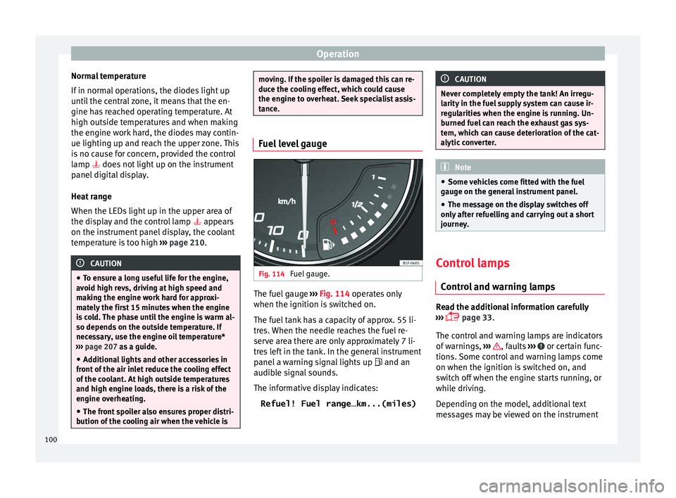
tance. Fuel level gauge
Fig. 114
Fuel gauge. The fuel gauge
››
›
Fig. 114 operates only
when the ignition is switched on.
The fuel tank has a capacity of approx. 55 li-
tres. When the needle reaches the fuel re-
serve area there are only approximately 7 li-
tres left in the tank. In the general instrument
panel a warning signal lights up and an
audible signal sounds.
The informative display indicates:
Refuel! Fuel range…km...(miles) CAUTION
Never completely empty the tank! An irregu-
larity in the f
uel supply system can cause ir-
regularities when the engine is running. Un-
burned fuel can reach the exhaust gas sys-
tem, which can cause deterioration of the cat-
alytic converter. Note
● Some v ehic
les come fitted with the fuel
gauge on the general instrument panel.
● The message on the display switches off
only af
ter refuelling and carrying out a short
journey. Control lamps
C ontr
o
l and warning lamps Read the additional information carefully
› ›
›
page 33.
The control and warning lamps are indicators
of warnings, ››› , faults
››
›
or certain func-
tion s.
Some c
ontrol and warning lamps come
on when the ignition is switched on, and
switch off when the engine starts running, or
while driving.
Depending on the model, additional text
messages may be viewed on the instrument
100
Page 113 of 248
Opening and closing
Note
If it is not possible to unlock or lock the vehi-
cl e w
ith the remote control key once the bat-
tery has been replaced, it will need to be re-
synchronised ››› page 109. Central locking system
Genera l
notesAll of
the doors, the rear lid and the fuel cap
fl ap 1)
w
ill unlock at the same time when the
central locking system is used.
Warning lamp on the driver door
Once the doors are locked, the warning lamp
will flash quickly for 2 seconds and then at a
slower rate.
If the vehicle is locked with Safe lock engag-
ed ›››
page 112, the warning lamp on the
driver door will flash quickly for 2 seconds
before switching off for 30 seconds and then
flashing at a slower rate.
If the warning lamp flashes quickly for 2 sec-
onds and then remains switched on before
flashing at a slower rate after 30 seconds,
there is a fault in the interior monitor and tow-away protection system
›››
page 117. Go
to a technical service.
Individualised settings Unlocking single doors
This
option
al function unlocks the driver door
only. The other doors remain locked and are
only unlocked when the next command is giv-
en (unlock).
Automatic unlock and lock
The doors and the rear lid are locked auto-
matically when the vehicle reaches a speed
of about 15 km/h (9 mph).
The doors unlock automatically when the key
is removed from the ignition. Additionally,
the driver or front passenger can unlock the
doors by pressing the ›››
page 113 central
lock button or by pulling the front door han-
dle. WARNING
Locking the doors prevents intruders from
gettin g int
o the car, e.g. while waiting at in-
tersections. However, it can also delay assis-
tance in the event of an accident. Risk of
death! Note
● Activ ation of
the single door setting can be
requested at your SEAT dealer.
● In the event of an accident in which the air-
bags
deploy, the doors will be automatically
unlocked for easier access and assistance.
● If the central locking system should fail to
work at
any time, only the driver door can be
locked or unlocked using the key
››› page 112. All other doors and the rear lid
can be operated manually.
–Manual release ›››
page 10.
– Manual release mechanism for the rear
lid ›››
page 10. 1)
Valid for vehicles with a keyless fuel tank cap.
111
Technical data
Advice
Operation
Emergencies
Safety
Page 114 of 248
Operation
Unlocking with key Fig. 122
Key positions during vehicle locking
and u n
loc
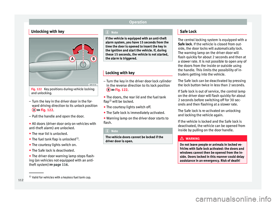
king. –
Turn the key in the driver door in the for-
war
d driv
ing direction to its unlock position
A
› ›
›
Fig. 122.
– Pull the handle and open the door.
● All doors (driver door only on vehicles with
anti-theft al
arm) are unlocked.
● The rear lid is unlocked.
● The fuel tank flap is unlocked 1)
.
● The courtesy lights switch on.
● The Safe lock is deactivated.
● The driver door warning lamp stops flash-
ing (on v
ehicles not equipped with an anti-
theft system) ›››
page 116. Note
If the vehicle is equipped with an anti-theft
al arm sy
stem, you have 15 seconds from the
time the door is opened to insert the key in
the ignition and start the vehicle. If, during
these 15 seconds, the vehicle is not started,
the alarm is triggered. Locking with key
–
Turn the key in the driver door lock cylinder
in the rev er
se direction to its lock position
B
› ›
›
Fig. 122.
● The doors, the rear lid and the fuel tank
flap 1)
wi
ll be locked.
● The courtesy lights switch off.
● The Safe lock is immediately activated.
● Warning lamp on the driver door starts to
flash. Note
The vehicle doors cannot be locked if the
driver door i s
open. Safe Lock
The central locking system is equipped with a
Safe loc
k
. If the vehicle is closed from out-
side, the door locks will automatically lock.
The warning lamp on the driver door will
flash quickly for about 2 seconds and then at
a slower rate. It is not possible to open any of
the doors from the inside or outside using
the handle. This limits the possibility of in-
truders getting into the vehicle.
The Safe lock can be deactivated by pressing
the lock button twice in less than 2 seconds.
If Safe lock is out of service, the control lamp
on the driver door will flash quickly for about
2 seconds before switching off for 30 sec-
onds and then flashing at a slower rate.
The Safe lock is re-activated on unlocking
and locking the vehicle again.
If the vehicle is locked and the Safe lock is
deactivated, the vehicle can be opened from
inside by pulling on the door handle. WARNING
Do not leave people or animals in locked ve-
hicl e
s with Safe lock activated: the doors and
windows cannot then be opened from the in-
side. Doors locked in this manner could delay
assistance in an emergency. Risk of death! 1)
Valid for vehicles with a keyless fuel tank cap.
112
Page 115 of 248
Opening and closing
Note
● The anti-theft a
larm switches on automati-
cally when the vehicle is locked, even if the
Safe lock is deactivated. The Vehicle interior
monitoring, however, is not activated.
● Given that the Safe function will be activa-
ted on lock
ing the vehicle, CHECK DEADLOCK
will be shown on the general instrument pan-
el display. On vehicles equipped with an in-
formative display, Caution SAFE! On- board documentation! Central locking button
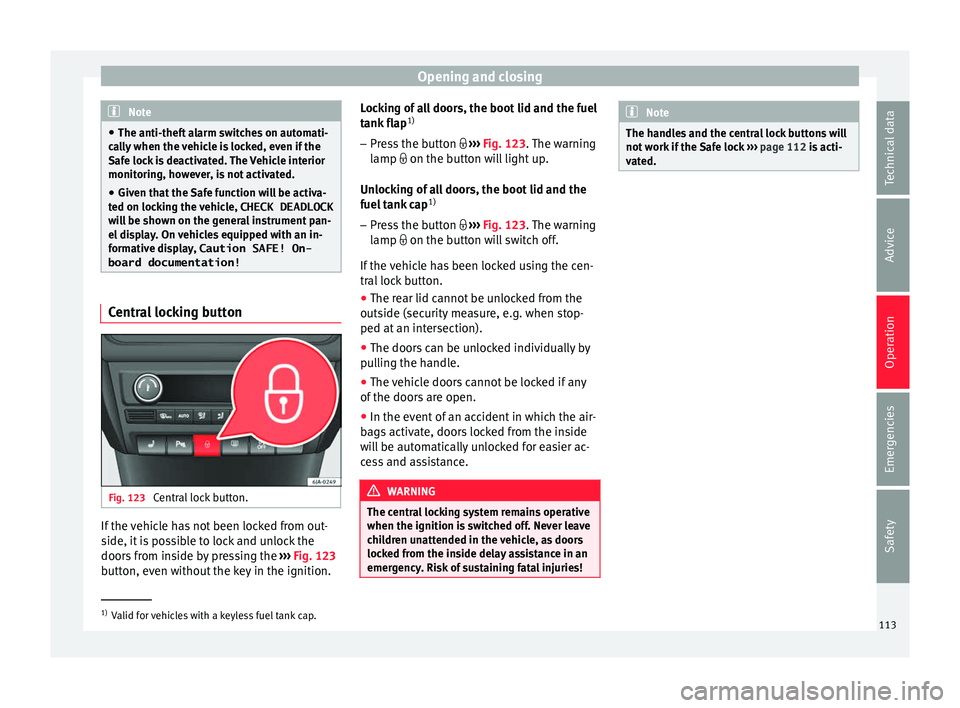
Fig. 123
Central lock button. If the vehicle has not been locked from out-
s
ide, it
i
s possible to lock and unlock the
doors from inside by pressing the ›››
Fig. 123
button, even without the key in the ignition. Locking of all doors, the boot lid and the fuel
tank fl
ap1)
– Press the button ›››
Fig. 123. The warning
lamp on the button will light up.
Unlocking of all doors, the boot lid and the
fuel tank cap 1)
– Press the button ›››
Fig. 123. The warning
lamp on the button will switch off.
If the vehicle has been locked using the cen-
tral lock button.
● The rear lid cannot be unlocked from the
outside (security
measure, e.g. when stop-
ped at an intersection).
● The doors can be unlocked individually by
pul
ling the handle.
● The vehicle doors cannot be locked if any
of the doors
are open.
● In the event of an accident in which the air-
bags
activate, doors locked from the inside
will be automatically unlocked for easier ac-
cess and assistance. WARNING
The central locking system remains operative
when the ignition is sw
itched off. Never leave
children unattended in the vehicle, as doors
locked from the inside delay assistance in an
emergency. Risk of sustaining fatal injuries! Note
The handles and the central lock buttons will
not w ork
if the Safe lock ››› page 112 is acti-
vated. 1)
Valid for vehicles with a keyless fuel tank cap.
113
Technical data
Advice
Operation
Emergencies
Safety
Page 148 of 248
Operation
Air conditioning
He atin
g and air c
onditioning
General notes The power of the heating depends on the
temper
at
ure of the coolant. Therefore, maxi-
mum power is only obtained when the en-
gine has reached operating temperature.
The temperature and humidity of the air in-
side the vehicle decrease when the cooling
system is turned on. This therefore increases
the comfort of all vehicle occupants when
outside temperatures and humidity are high.
It also helps prevent the windows from mist-
ing over during cold periods of the year.
The air recirculation system can be switched
on temporarily to increase the cooling effect.
Keep the air intake slots in front of the wind-
screen clear of ice, snow or leaves to ensure
unimpaired heating and cooling.
When the air conditioning is on, condensa-
tion can drip from the evaporator in the air
cooling system and form a pool underneath
the vehicle. This is normal and does not indi-
cate a leak! WARNING
● All
windows must be clear of ice, snow and
condensation for driving safety. Therefore, make sure you familiarise yourself with the
corr
ect
use of heating and ventilation, win-
dow demisting and defrosting and cooling.
● Never use the air recirculation system for
too long, a
s it prevents fresh air from enter-
ing the vehicle and used air can cause tired-
ness, reduce your attention span and cause
the windows to mist over. This increases the
risk of an accident. Switch off the air recircu-
lation system as soon as the windows begin
to mist over. WARNING
Do not switch off Climatronic for longer than
nece s
sary.
● Switch Climatronic back on as soon as the
window
s begin to mist over. Note
● Used air e s
capes through ventilation slots
in the rear of the luggage compartment.
● Smoking is not recommended while the air
recir
culation system is in use, as the smoke
drawn from the interior of the vehicle settles
in the evaporator of the air conditioning sys-
tem. This causes a persistent, unpleasant
smell while the system is running that is
time-consuming and expensive (evaporator
replacement) to eliminate.
● To guarantee proper operation, never cover
the air outlets
in the luggage compartment. Economic use of the air-conditioning
sy
s
t
em When the air conditioning is switched on, the
compr
e
ssor consumes engine power and has
influence on fuel consumption.
If the vehicle interior has overheated due to
excessive solar radiation, it is best to open
the windows or doors to allow the hot air to
escape.
While in motion, the air conditioning should
not be switched on if the windows are open.
If the interior temperature can be reached
without switching on the air conditioning, the
fresh air mode should be used. For the sake of the environment
Saving fuel reduces emissions. Faults
If the air conditioning does not work at out-
s
ide t
emper
atures above +5°C (+41°F) then
the system is faulty. This may be due to one
of the following reasons:
● One of the fuses has blown. Check the fuse
and repl
ace if necessary ›››
page 81.
146
Page 167 of 248
Driving
displayed when the gearbox has cooled
ag ain.
R u
n-in and economical driving
The first
1,500 kmOver the first 1,500 kilometres the engine
mus
t
be run in.
Up to 1000 kilometres
– Do not drive at more than 3/4 of the maxi-
mum speed c orr
esponding to the engaged
gear, i.e. up to 3/4 of the maximum permit-
ted engine speed.
– Do not drive at full speed.
– Avoid high engine speeds.
– Do not tow a trailer.
From 1000 to 1500 k
ilometres (600 to 900
miles)
– Slowly increase the engine speed until
re
aching the maximum permitted speed of
the engaged gear, i.e. the maximum per-
mitted engine speed.
During its first few hours of running, the in-
ternal friction in the engine is greater than
later on, when all the moving parts have bed-
ded in. How the vehicle is driven over approx-
imately the first 1,500 kilometres (900 miles), determines the success of the proc-
ess
of running in the engine.
Even after running in, the vehicle should not
be unnecessarily driven at high engine
speeds. The maximum permitted engine
speed is marked at the start of the red zone
on the rev counter dial. The gear must be
changed up when the red area is reached in
vehicles with a manual gearbox. Extremely
high engine speeds when accelerating are
automatically limited, however the engine is
not protected against high engine speeds
produced by incorrectly changing to a lower
gear, which could cause the engine to run at
revs above the maximum permitted amount,
and consequently result in damage to the en-
gine.
Additionally, vehicles with a manual gearbox
must also bear the following in mind: do not
drive with the engine speed too low. Change
down to a lower gear when the engine no
longer runs smoothly. Observe the recom-
mendations for changing gear
››› page 29.
New tyres
New tyres must be submitted to “running in”,
given that initially their grip is not yet at the
maximum level. During the first 500 km (120
miles) drive very carefully. New brake pads
New brake p
ads do not yet provide maximum
friction capacity. First they must be “run in”.
During the first 200 km (120 miles) drive very
carefully. CAUTION
All the information for speed and engine
speed r ef
ers to an engine that operates at op-
erating temperature. Do not run the engine at
high engine speeds, neither when stopped or
while driving. For the sake of the environment
Do not drive at unnecessarily high engine
speed s; c
hanging to a higher gear sooner
contributes to saving fuel, reduces operating
noise and protects the environment. Environmental compatibility
Environmental protection is a top priority in
the de
s
ign, c
hoice of materials and manufac-
ture of your new SEAT.
Constructive measures to encourage recy-
cling
● Joints and connections designed for easy
dismantlin
g.
● Modular construction to facilitate disman-
tling. »
165
Technical data
Advice
Operation
Emergencies
Safety