Temp SKODA CITIGO 2013 1.G Owner's Manual
[x] Cancel search | Manufacturer: SKODA, Model Year: 2013, Model line: CITIGO, Model: SKODA CITIGO 2013 1.GPages: 176, PDF Size: 10.54 MB
Page 13 of 176
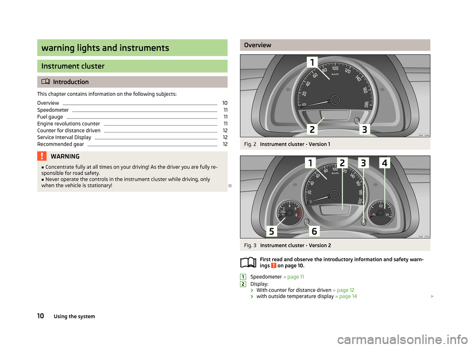
warning lights and instruments
Instrument cluster
Introduction
This chapter contains information on the following subjects:
Overview
10
Speedometer
11
Fuel gauge
11
Engine revolutions counter
11
Counter for distance driven
12
Service Interval Display
12
Recommended gear
12WARNING■ Concentrate fully at all times on your driving! As the driver you are fully re-
sponsible for road safety.■
Never operate the controls in the instrument cluster while driving, only
when the vehicle is stationary!
OverviewFig. 2
Instrument cluster - Version 1
Fig. 3
Instrument cluster - Version 2
First read and observe the introductory information and safety warn-
ings
on page 10.
Speedometer » page 11
Display:
› With counter for distance driven
» page 12
› with outside temperature display
» page 14
1210Using the system
Page 15 of 176
Follow the recommended gear to prevent engine speeds that are too high or too
low » page 12 .
Avoid high engine speeds during the running-in period and before the engine has warmed up to the operating temperature .
For the sake of the environment
Correct shifting up has the following advantages.■It helps to reduce fuel consumption.■
It reduces the operating noise.
■
It protects the environment.
■
It benefits the durability and reliability of the engine.
Counter for distance driven
First read and observe the introductory information and safety warn-
ings
on page 10.
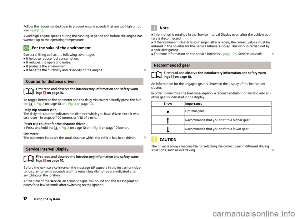
To toggle between the odometer and the daily trip counter, briefly press the but-
ton
3
» Fig. 2 on page 10 or » Fig. 3 on page 10 .
Daily trip counter (trip)
The daily trip counter indicates the distance which you have driven since it was last reset - in steps of 100 metres or 1/10 of a mile.
Reset trip counter for the distance driven
›
Press and hold the
3
» Fig. 2 on page 10 or » Fig. 3 on page 10 button.
Odometer
The odometer indicates the total distance which the vehicle has been driven.
Service Interval Display
First read and observe the introductory information and safety warn-
ings
on page 10.
Before the next service interval, the message
appears in the instrument clus-
ter display for some seconds and the remaining kilometres are indicated after
switching on the ignition.
At the time of the service, an acoustic signal will sound and the message
ap-
pears for a few seconds after switching on the ignition.
Note■ Information is retained in the Service Interval Display even after the vehicle bat-
tery is disconnected.■
If the instrument cluster is exchanged after a repair, the correct values must be
entered in the counter for the Service Interval Display. This work is carried out by a specialist garage.
■
For more information on the service intervals » page 108, Service intervals .
Recommended gear
First read and observe the introductory information and safety warn-
ings
on page 10.
An information for the engaged gear is shown in the display of the instrument
cluster.
In order to minimise the fuel consumption, a recommendation for shifting into an-
other gear is indicated in the display.
ShowImportanceOptimal gear.Recommends that you shift to a higher gear.Recommends that you shift to a lower gear.
CAUTION
The driver is always responsible for selecting the correct gear in different driving
situations, such as overtaking.
12Using the system
Page 16 of 176
Multifunction display (MFA)
Introduction
This chapter contains information on the following subjects:
Memory
13
Operation
14
Digital clock
14
Multifunction display details
14
Warning against excessive speeds
15
The driving data is displayed on the multifunction display. The multifunction display can only be operated when the ignition is switched on.
After the ignition is switched on, the function displayed is the one which you last
selected before switching off the ignition.
WARNING■ Concentrate fully at all times on your driving! As the driver you are fully re-
sponsible for the operation of your vehicle.■
Even at temperatures of around +4 °C, black ice may still be on the road sur-
face! You should therefore not only rely on the outside temperature display
for accurate information as to whether there is ice on the road.
Note
In certain national versions the displays appear in the Imperial system of meas-
ures.
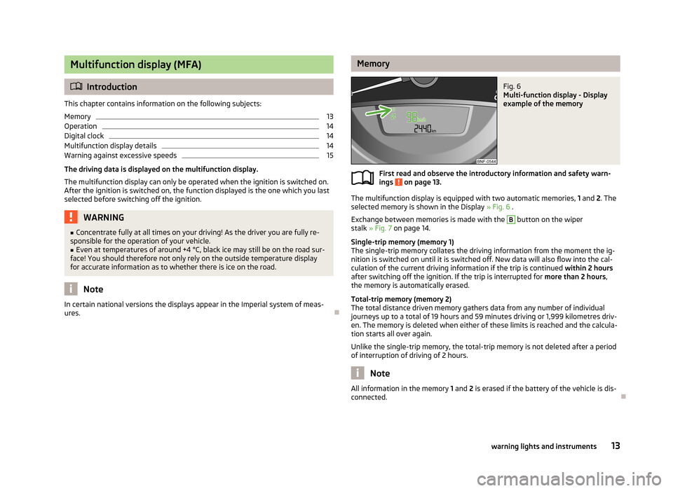
MemoryFig. 6
Multi-function display - Display
example of the memory
First read and observe the introductory information and safety warn-
ings on page 13.
The multifunction display is equipped with two automatic memories, 1 and 2. The
selected memory is shown in the Display » Fig. 6 .
Exchange between memories is made with the
B
button on the wiper
stalk » Fig. 7 on page 14.
Single-trip memory (memory 1)
The single-trip memory collates the driving information from the moment the ig-
nition is switched on until it is switched off. New data will also flow into the cal-
culation of the current driving information if the trip is continued within 2 hours
after switching off the ignition. If the trip is interrupted for more than 2 hours,
the memory is automatically erased.
Total-trip memory (memory 2)
The total distance driven memory gathers data from any number of individual
journeys up to a total of 19 hours and 59 minutes driving or 1,999 kilometres driv-
en. The memory is deleted when either of these limits is reached and the calcula-
tion starts all over again.
Unlike the single-trip memory, the total-trip memory is not deleted after a period of interruption of driving of 2 hours.
Note
All information in the memory 1
and 2 is erased if the battery of the vehicle is dis-
connected.
13warning lights and instruments
Page 17 of 176
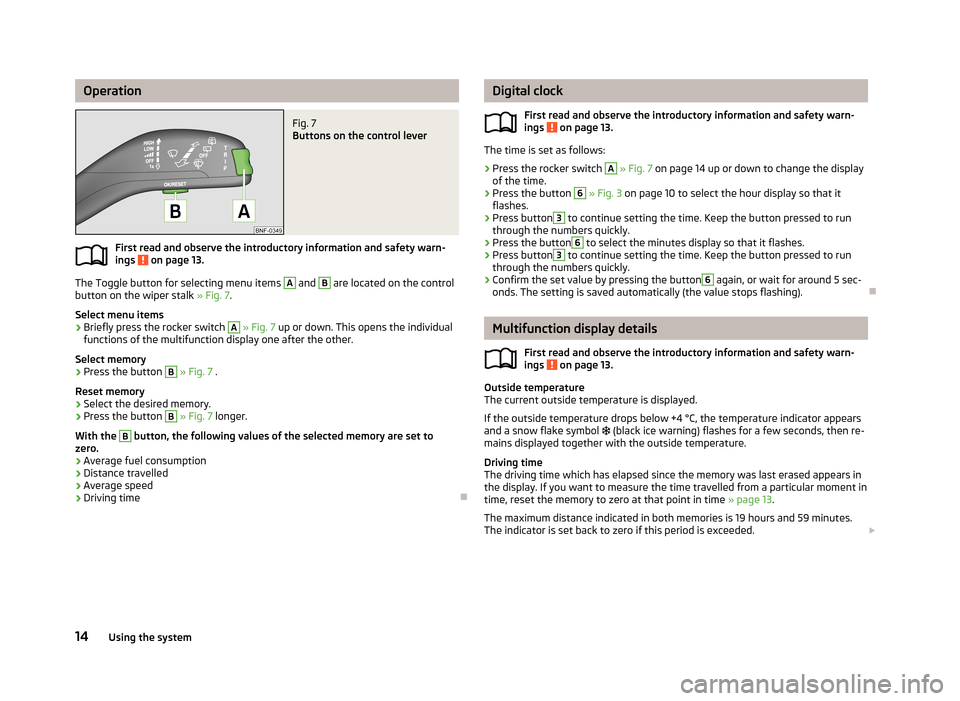
OperationFig. 7
Buttons on the control lever
First read and observe the introductory information and safety warn-ings on page 13.
The Toggle button for selecting menu items
A
and
B
are located on the control
button on the wiper stalk » Fig. 7.
Select menu items
›
Briefly press the rocker switch
A
» Fig. 7 up or down. This opens the individual
functions of the multifunction display one after the other.
Select memory
›
Press the button
B
» Fig. 7 .
Reset memory
›
Select the desired memory.
›
Press the button
B
» Fig. 7 longer.
With the
B
button, the following values of the selected memory are set to
zero.
› Average fuel consumption
› Distance travelled
› Average speed
› Driving time
Digital clock
First read and observe the introductory information and safety warn-ings
on page 13.
The time is set as follows:
›
Press the rocker switch
A
» Fig. 7 on page 14 up or down to change the display
of the time.
›
Press the button
6
» Fig. 3 on page 10 to select the hour display so that it
flashes.
›
Press button
3
to continue setting the time. Keep the button pressed to run
through the numbers quickly.
›
Press the button
6
to select the minutes display so that it flashes.
›
Press button
3
to continue setting the time. Keep the button pressed to run
through the numbers quickly.
›
Confirm the set value by pressing the button
6
again, or wait for around 5 sec-
onds. The setting is saved automatically (the value stops flashing).
Multifunction display details
First read and observe the introductory information and safety warn-
ings
on page 13.
Outside temperature
The current outside temperature is displayed.
If the outside temperature drops below +4 °C, the temperature indicator appears
and a snow flake symbol
(black ice warning) flashes for a few seconds, then re-
mains displayed together with the outside temperature.
Driving time
The driving time which has elapsed since the memory was last erased appears in the display. If you want to measure the time travelled from a particular moment in
time, reset the memory to zero at that point in time » page 13.
The maximum distance indicated in both memories is 19 hours and 59 minutes.
The indicator is set back to zero if this period is exceeded.
14Using the system
Page 18 of 176
Current fuel consumption
The current fuel consumption level is displayed in litres/100 km 1)
. You can use this
information to adapt your driving style to the desired fuel consumption.
The display appears in litres/hour if the vehicle is stationary or driving at a low
speed 2)
.
Average fuel consumption
The average fuel consumption since the memory was last erased is displayed in
litres/100 km 1 )
.
If you wish to determine the average fuel consumption over a certain period of
time, you must set the memory at the start of the new measurement to zero » page 13 . After erasing the memory, no value is displayed until you have
driven approx. 300 m.
The display is updated regularly while you are driving.
Range
The estimated range is displayed in kilometres. It indicates the distance you can still drive with your vehicle based on the level of fuel in the tank and the same
style of driving.
The display is shown in steps of 10 km. After lighting up of the warning light for
the fuel reserve the display is shown in steps of 5 km.
The fuel consumption over the last 50 km is used to calculate the information.The range will increase if you drive in a more economical manner.
Distance travelled
The distance travelled since the memory was last erased is displayed » page 13. If
you want to measure the distance travelled from a particular moment in time, re-
set the memory to zero at that moment in time » page 13.
The maximum distance indicated in both memories is 1 999 km. The indicator is
set back to zero if this period is exceeded.
Average speed
The average speed since the memory was last erased is displayed in km/hour . To determine the average speed over a certain period of time, set the memory to
zero at the start of the measurement » page 13.After erasing this data, no value appears in the display until you have driven ap-
prox. 300 m.
The display is updated regularly while you are driving.
Current speed
The current speed, which is identical to the display of the speedometer 1
» Fig. 3
on page 10 is displayed.
Coolant temperature
The current outside temperature is displayed.
Warning against excessive speeds
The warning that the speed limit is being exceeded can be enabled / disa-
bled » page 15 , Warning against excessive speeds in the display.
Warning against excessive speeds
First read and observe the introductory information and safety warn-ings
on page 13.
Adjust the speed limit while the vehicle is stationary
›
With button
A
» Fig. 7 on page 14 choose the menu point
Warning against
excessive speeds.
›
Press the button
B
to activate the ability to set the speed limit (value flashes).
›
Use the button
A
to set the required speed limit, e.g. 50 km/h.
›
Confirm the speed limit that was set with button
B
, or wait approx. 5 seconds
until the setting is saved automatically (the value stops flashing).
This allows you to set the speed in 5 km/h intervals.
Adjusting the speed limit while the vehicle is moving
›
With button
A
» Fig. 7 on page 14 choose the menu point
Warning against
excessive speeds.
›
Drive at the desired speed, e.g. 50 km/h.
›
Press button
B
to accept the current speed as the speed limit (the value flash-
es).
If you wish to adjust the set speed limit, you can do so in 5 km/h intervals (e.g. the
accepted speed of 47 km/h increases to 50 km/h or decreases to 45 km/h).
1)
On some models in certain countries, the display appears in kilometres/litre.
2)
On some models in certain countries, the display appears in --,- kilometres/litres if the vehicle is sta-
tionary.
15warning lights and instruments
Page 21 of 176
CAUTIONThe red oil pressure light is not an oil level indicator! One should therefore
check the oil level at regular intervals, preferably after every refuelling stop.
Coolant
First read and observe the introductory information and safety warn-ings
on page 16.
The warning light comes on for a few seconds when the ignition is switched
on.
If the warning light
lights up or flashes, either the coolant temperature is too
high or the coolant level is too low.
An audible signal sounds as a warning tone.
Stop the vehicle, switch off the engine, check the level of the coolant » page 132,
and refill the coolant if necessary » page 133.
Do not continue your journey if for some reason it is not possible to top up the
coolant under the prevailing conditions. This can cause serious engine damage.
Therefore, switch the engine off and seek help from a specialist garage.
If the coolant is within the specified range, the increased temperature may be
caused by an operating problem at the radiator fan. Check the fuse for the radia-
tor fan, replace if necessary » page 156, Fuses in the engine compartment .
Do not continue driving if the warning light
does not go off even though the
coolant level is correct and the fuse for the fan is in working order!
Seek help from a specialist garage.
WARNINGIf you have to stop for technical reasons, then park the vehicle at a safe dis- tance from the traffic, switch off the engine and activate the hazard warning
lights » page 36 .
Power steering
First read and observe the introductory information and safety warn-
ings
on page 16.
The warning light comes on for a few seconds when the ignition is switched
on.
If the warning light after switching on the ignition or when driving lights up con-
tinuously, a fault exists in the electromechanical power steering.
› If the
yellow warning light lights up
, this indicates a partial failure of the
power steering and the steering forces can be greater.
› If the
red warning light lights up
, this indicates a complete failure of the pow-
er steering and the steering assist has failed (significantly higher steering forces).
Further information » page 66.
Note
■
If the yellow warning light goes out after starting the engine again and driv-
ing a short distance, it is not necessary to visit a specialist garage.■
If the vehicle battery has been disconnected and reconnected, the yellow warn-
ing light comes on after switching on the ignition. The warning light should go
out after driving a short distance.
Electronic Stability Control (ESC)
First read and observe the introductory information and safety warn-
ings
on page 16.
The warning light flashes
to show that the ESC is currently operating.
If the warning light
lights up, there is a fault in the ESC.
As the ESC operates in conjunction with the ABS, the ESP warning light will also come on if the ABS system fails.
If the warning light
comes on immediately after starting the engine, the ESC
can be switched off for technical reasons. In this case, the ESC can be switched on again by switching the ignition on and off. If the warning light goes out, the ESC is fully functional again.
Further information » page 80, Electronic Stability Control (ESC) .
18Using the system
Page 25 of 176
Unlocking and locking
Unlocking and locking
Introduction
This chapter contains information on the following subjects:
Vehicle key
22
Replacing the battery in the remote control key
23
Child safety lock
23
Opening/closing a door
24
Door opening lever
24
Emergency locking of the doors
25
Vehicle key
Fig. 8
Key: without/with remote control
First read and observe the introductory information given on page 22.
Two keys are provided with the vehicle » Fig. 8.
Keys without remote control
Keys with remote control (remote control keys)
WARNING■ Always withdraw the key whenever you leave the vehicle – even if it is only
for a short time. This is particularly important if children are left in the vehicle.
The children might otherwise start the engine or operate electrical equipment
(e.g. power windows) – risk of injury!■
Do not withdraw the ignition key from the ignition lock until the vehicle has
come to a stop. The steering lock might otherwise engage unintentionally –
risk of accident!
CAUTION
■ Each key contains electronic components; therefore it must be protected
against moisture and severe shocks.■
Keep the groove of the keys absolutely clean. Impurities (textile fibres, dust,
etc.) have a negative effect on the functionality of the locking cylinder and igni-
tion lock.
■
The function of the remote control may temporarily be affected by interference
from transmitters located near the vehicle that operate in the same frequency
range (e.g. mobile phones, television transmitters).
■
The battery must be replaced if the central locking does react to the remote
control at less than around 3 metres away » page 23.
Note
If you lose a key, please contact a specialist garage, who will be able to provide
you with a new one.
22Using the system
Page 29 of 176
Safe securing systemFirst read and observe the introductory information and safety warn-
ings
on page 25.
The central locking system is equipped with a safe securing system. The door
locks are blocked automatically if the vehicle is locked from the outside. The warning light flashes for around 2 seconds in quick succession, afterwards it be-gins to flash evenly at longer intervals. It is not possible to open the doors withthe door handle either from the inside or from the outside. This acts as an effec-
tive deterrent against attempts to break into your vehicle.
The safe securing system can be deactivated within 2 seconds by double locking
the vehicle.
If the safe securing system is not operating, the warning light in the driver door flashes for about 2 seconds fast, goes out and starts to flash evenly at longer in-
tervals after about 30 seconds.
The safe securing system is activated again the next time the vehicle is unlocked and locked.
If the vehicle is locked and the safe securing system is deactivated, the door can
be opened from the inside by a single pull on opening lever of the respective
door.
WARNINGIf the vehicle is locked from the outside and the safe securing system is acti-
vated, there must not be any person in the vehicle as it is then no longer pos-
sible to open either a door or a window from the inside. The locked doors
make it more difficult for rescuers to get into the vehicle in an emergency – risk to life!
Note
You will be informed that the safe securing system has been activated after the
vehicle has been locked by means of the message on the instrument clus-
ter display.
Unlocking the vehicle using the keyFig. 14
Left side of the vehicle: Turning
the key for unlocking and lock-
ing the vehicle
First read and observe the introductory information and safety warn- ings on page 25.
›
Turn the key in the locking cylinder of the driver's door in the direction of travel
(unlocking position)
A
» Fig. 14 .
›
Pull the door handle and open the door.
› All the doors are unlocked.
› The luggage compartment lid is then unlocked.
› The switched on interior lights come on over the door contact.
› The safe securing system is deactivated.
Locking the vehicle with the key
First read and observe the introductory information and safety warn-
ings
on page 25.
›
Turn the key in the locking cylinder of the driver's door in the opposite direction
of travel (lock position)
B
» Fig. 14 on page 26.
› All the doors and the luggage compartment lid are locked.
› The switched on interior lights will switch off over the door contact.
› The safe securing system is immediately activated.
› The warning light in the driver door begins flashing.
Note
If the driver's door has been opened, the vehicle cannot be locked.
26Using the system
Page 30 of 176
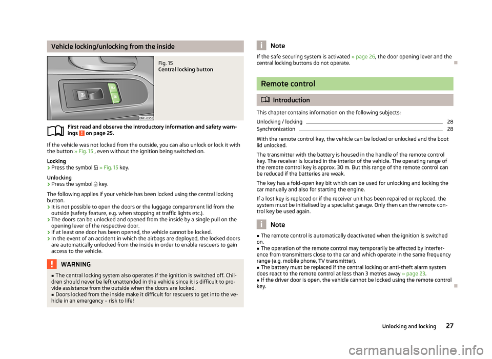
Vehicle locking/unlocking from the insideFig. 15
Central locking button
First read and observe the introductory information and safety warn-ings on page 25.
If the vehicle was not locked from the outside, you can also unlock or lock it with
the button » Fig. 15 , even without the ignition being switched on.
Locking
›
Press the symbol
» Fig. 15 key.
Unlocking
›
Press the symbol
key.
The following applies if your vehicle has been locked using the central locking button.
› It is not possible to open the doors or the luggage compartment lid from the
outside (safety feature, e.g. when stopping at traffic lights etc.).
› The doors can be unlocked and opened from the inside by a single pull on the
opening lever of the respective door.
› If at least one door has been opened, the vehicle cannot be locked.
› In the event of an accident in which the airbags are deployed, the locked doors
are automatically unlocked from the inside in order to enable rescuers to gain
access to the vehicle.
WARNING■ The central locking system also operates if the ignition is switched off. Chil-
dren should never be left unattended in the vehicle since it is difficult to pro-
vide assistance from the outside when the doors are locked.■
Doors locked from the inside make it difficult for rescuers to get into the ve-
hicle in an emergency – risk to life!
NoteIf the safe securing system is activated » page 26, the door opening lever and the
central locking buttons do not operate.
Remote control
Introduction
This chapter contains information on the following subjects:
Unlocking / locking
28
Synchronization
28
With the remote control key, the vehicle can be locked or unlocked and the boot
lid unlocked.
The transmitter with the battery is housed in the handle of the remote control
key. The receiver is located in the interior of the vehicle. The operating range of
the remote control key is approx. 30 m. But this range of the remote control can
be reduced if the batteries are weak.
The key has a fold-open key bit which can be used for unlocking and locking the
car manually and also for starting the engine.
If a lost key is replaced or if the receiver unit has been repaired or replaced, thesystem must be initialised by a specialist garage. Only then can the remote con-
trol key be used again.
Note
■ The remote control is automatically deactivated when the ignition is switched
on.■
The operation of the remote control may temporarily be affected by interfer-
ence from transmitters close to the car and which operate in the same frequency
range (e.g. mobile phone, TV transmitter).
■
The battery must be replaced if the central locking or anti-theft alarm system
does react to the remote control at less than 3 metres away » page 23.
■
If the driver door is open, the vehicle cannot be locked using the remote control
key.
27Unlocking and locking
Page 36 of 176
Lights and visibility
Lights
Introduction
This chapter contains information on the following subjects:
Lights and low beam
33
Headlight beam adjustment
34
Daytime running light (DAY LIGHT)
34
Turn signal and main beam
34
Fog lights
35
Rear fog light
35
Hazard warning light system
36
Parking light
36
Unless otherwise stated, the lights only work when the ignition is on.
On models fitted with right-hand steering the position of the controls differs
from that shown in » Fig. 22 on page 33 . The symbols which mark the positions
of the controls are however identical.
WARNING■ The activation of the lights should only be undertaken in accordance with
national legal requirements.■
The driver is always responsible for the correct settings and use of the
lights.
■
Never drive with only the side lights on! The side lights are not bright
enough to light up the road sufficiently in front of you or to be seen by other oncoming traffic. Therefore always switch on the low beam when it is dark or
if visibility is poor.
Note■ The instruments are also illuminated when the side light or low beam light is
switched on.■
The headlights may mist up temporarily. When the driving lights are switched
on, the light outlet surfaces are free from mist after a short period, although the
headlight lenses may still be misted up in the peripheral areas. This mist has no
influence on the life of the lighting system.
Lights and low beam
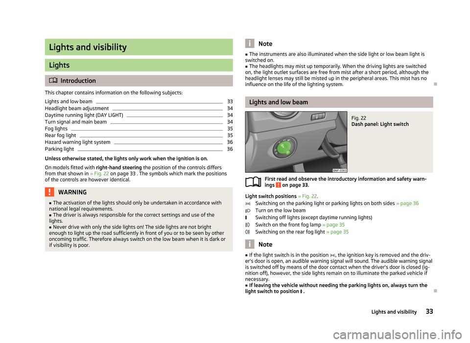
Fig. 22
Dash panel: Light switch
First read and observe the introductory information and safety warn-
ings on page 33.
Light switch positions » Fig. 22 .
Switching on the parking light or parking lights on both sides » page 36
Turn on the low beam
Switching off lights (except daytime running lights)
Switch on the front fog lamp » page 35
Switching on the rear fog light » page 35
Note
■
If the light switch is in the position , the ignition key is removed and the driv-
er's door is open, an audible warning signal will sound. The audible warning signal
is switched off by means of the door contact when the driver's door is closed (ig- nition off), however, the side lights remain on to illuminate the parked vehicle ifnecessary.■
If leaving the vehicle without needing the parking lights on, always turn the
light switch to position .
33Lights and visibility