engine SKODA FABIA 2000 1.G / 6Y Repair Manual
[x] Cancel search | Manufacturer: SKODA, Model Year: 2000, Model line: FABIA, Model: SKODA FABIA 2000 1.G / 6YPages: 86, PDF Size: 3.58 MB
Page 61 of 86
Downloaded from www.Manualslib.com manuals search engine FABIA 2000➤Inspection and Maintenance
Electrical SystemEdition 09.04
S00.5301.14.2002-6 page 7 02
♦For vehicles with the dash panel insert 6Y0 920 xxx x,
the SID with the set button -1- cannot be reset before
a service is required.
♦Always only reset the desired service interval („OIL
service“ or „INSP service“), otherwise an incorrect
date for another service interval will be set.
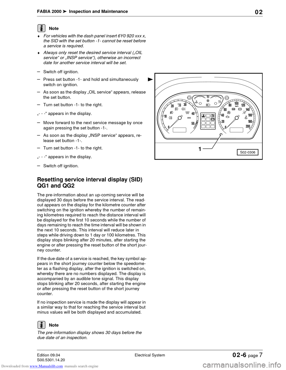
–Switch off ignition.
–Press set button -1- and hold and simultaneously
switch on ignition.
–As soon as the display „OIL service“ appears, release
the set button.
–Turn set button -1- to the right.
„- - -“ appears in the display.
–Move forward to the next service message by once
again pressing the set button -1-.
–As soon as the display „INSP service“ appears, re-
lease set button -1-.
–Turn set button -1- to the right.
„- - -“ appears in the display.
–Switch off ignition.
Resetting service interval display (SID)
QG1 and QG2
The pre-information about an up-coming service will be
displayed 30 days before the service interval. The read-
out appears on the display for the kilometre counter after
switching on the ignition whereby the number of remain-
ing kilometres required to reach the distance interval will
be displayed for the first 10 seconds while the number of
days remaining to reach the time interval will be shown in
the next 10 seconds. This interval will reduce later in
steps while driving down to 1 day or 100 kilometres. This
display stops blinking after 20 minutes, after starting the
engine or after pressing the reset button of the short jour-
ney counter.
If the due date of a service is reached, the key symbol ap-
pears in the short journey counter below the speedome-
ter as a flashing display, after the ignition is switched on,
whereby there are no numbers displayed. The display is
accompanied by an audible tone signal. This display
stops blinking after 20 seconds, after starting the engine
or after pressing the reset button of the short journey
counter.
If no inspection service is made the display will appear in
a similar way to that for reaching the service interval but
minus values will be both displayed and accumulated.
The pre-information display shows 30 days before the
due date of an inspection.
Note
S02-03061
Note
Page 62 of 86

Downloaded from www.Manualslib.com manuals search engine FABIA 2000➤Inspection and Maintenance
Electrical SystemEdition 09.04
S00.5301.14.2002-6 page 8 02
Resetting service interval display (SID) with
-V.A.G 1552- (QG1, QG2)
–Connect -V.A.G 1552-.
–Switch on ignition.
–Enter address word 17 „Dash Panel Insert“ and con-
firm with .
Readout on display (e.g.):
–Note the dash panel insert coding.
–Press key.
Readout on display (e.g.):
–Press key.
Readout on display:
–Enter address word 10 „Adaptation“ and confirm with
the key.
Readout on display:
–Enter adjustment channel 02.
Readout on display:
–Press .
Readout on display:
–Enter adaptation value 00000.
Readout on display:
–Confirm the entry with key .
Read-out on display after entering adaptation value
00000:
–Confirm the entry with key .
Readout on display:
–Confirm the entry with key .
Readout on display:
–Press key.
Readout on display:
–Enter 06 for „End output“.
Readout on display:
–Confirm the entry with key .
–Switch off ignition.
Resetting service interval display (SID) without
-V.A.G 1552- (QG1, QG2)
–Switch off ignition.
Q
6Y1919870B COMBIINSTRUMENT VDO X09 ->
Coding 03111 WSC 12345
TMBMC46Y0Y7000001 SKZ7Z0W0204038 ->
Vehicle system test HELP
Select function XX
Q
Adjustment
Enter channel number XX
Channel 2 Adaptation 1
- -
Channel 2 Adaptation 1
Enter adjustment value XXXXX
Channel 2 adjustment 1 Q
Enter adaptation value 00000
Q
Channel 2 adjustment 0 Q
- -
Q
Channel 2 adjustment 0 Q
Store changed value?
Q
Channel 2 Adaptation 0
Changed value stored
Vehicle system test HELP
Select function XX
Vehicle system test HELP
06 - End output
Q
Page 63 of 86
Downloaded from www.Manualslib.com manuals search engine FABIA 2000➤Inspection and Maintenance
Electrical SystemEdition 09.04
S00.5301.14.2002-6 page 9 02
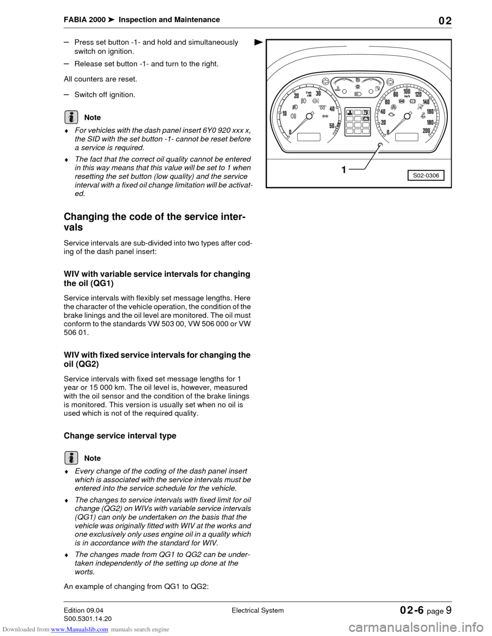
–Press set button -1- and hold and simultaneously
switch on ignition.
–Release set button -1- and turn to the right.
All counters are reset.
–Switch off ignition.
♦For vehicles with the dash panel insert 6Y0 920 xxx x,
the SID with the set button -1- cannot be reset before
a service is required.
♦The fact that the correct oil quality cannot be entered
in this way means that this value will be set to 1 when
resetting the set button (low quality) and the service
interval with a fixed oil change limitation will be activat-
ed.
Changing the code of the service inter-
vals
Service intervals are sub-divided into two types after cod-
ing of the dash panel insert:
WIV with variable service intervals for changing
the oil (QG1)
Service intervals with flexibly set message lengths. Here
the character of the vehicle operation, the condition of the
brake linings and the oil level are monitored. The oil must
conform to the standards VW 503 00, VW 506 000 or VW
506 01.
WIV with fixed service intervals for changing the
oil (QG2)
Service intervals with fixed set message lengths for 1
year or 15 000 km. The oil level is, however, measured
with the oil sensor and the condition of the brake linings
is monitored. This version is usually set when no oil is
used which is not of the required quality.
Change service interval type
♦Every change of the coding of the dash panel insert
which is associated with the service intervals must be
entered into the service schedule for the vehicle.
♦The changes to service intervals with fixed limit for oil
change (QG2) on WIVs with variable service intervals
(QG1) can only be undertaken on the basis that the
vehicle was originally fitted with WIV at the works and
one exclusively only uses engine oil in a quality which
is in accordance with the standard for WIV.
♦The changes made from QG1 to QG2 can be under-
taken independently of the setting up done at the
worts.
An example of changing from QG1 to QG2:
S02-03061
Note
Note
Page 64 of 86

Downloaded from www.Manualslib.com manuals search engine FABIA 2000➤Inspection and Maintenance
Electrical SystemEdition 09.04
S00.5301.14.2002-6 page 10 02
–Connect -V.A.G 1552-.
–Switch on ignition.
–Enter address word 17 „Dash Panel Insert“ and con-
firm with .
Readout on display (e.g.):
–Note the dash panel insert coding.
–Press key.
Readout on display (e.g.):
–Press key.
Readout on display:
–Enter function 07 „Code control unit“ and confirm with
key.
Readout on display:
–Enter dash panel insert coding which is identical to the
original coding. The value on the fourth position must,
however, be altered from 1 to 2.
XXX1X - QG1
XXX2X - QG2
Readout on display (e.g.):
–Confirm the entry with key .
Readout on display (e.g.):
–Press key.
Readout on display (e.g.):
–Press key.
Readout on display:
–Enter 06 for „End output“.
Readout on display:
–Confirm the entry with key .
–Switch off ignition.
–Switch off -V.A.G 1552-.
Inspecting headlight beam setting and
adjusting if necessary
Special tools, test and measuring equipment and
auxiliary items required
♦Headlight beam setting device
In principle the following inspection and setting descrip-
tion applies for all countries. However, comply with na-
tional guidelines and legislation of the relevant country.
⇒Operating instructions for the headlight beam setting
device
Q
6Y1919870B COMBIINSTRUMENT VDO X09 ->
Coding 03111 WSC 12345
TMBMC46Y0Y7000001 SKZ7Z0W0204038 ->
Vehicle system test HELP
Select function XX
Q
Coding control unit
Enter code number XXXXX (0-32767)
Coding control unit
Enter code number 03121 (0-32767)
Q
6Y1919870B COMBIINSTRUMENT VDO X09 ->
Coding 03121 WSC 12345
TMBMC46Y0Y7000001 SKZ7Z0W0204038 ->
Vehicle system test HELP
Select function XX
Vehicle system test HELP
06 End output
Q
Page 65 of 86
Downloaded from www.Manualslib.com manuals search engine FABIA 2000➤Inspection and Maintenance
Electrical SystemEdition 09.04
S00.5301.14.2002-6 page 11 02
Test and setting conditions
•Tyre inflation pressure O.K.
•Lenses must neither be damaged nor soiled.
•Reflectors and bulbs O.K.
•Vehicle load must be achieved.
Load: With an individual or 75 kg on the driver's seat in an
otherwise unladen vehicle (dead weight).
The unladen weight is the weight of the vehicle with full
fuel tank (at least 90 %) including the weight of all the op-
erational equipment elements (e.g. spare wheel, tool kit,
jack etc.).
The vehicle must have rolled a few metres or have been
depressed a few times at the front and rear to allow the
springs to settle.
•Both the vehicel and headlight beam setting device
must be on a level flat surface.
•Align the vehicle and headlight beam setting device in
accordance with the device manufaturer's indications.
•Check the control system of vehicles equipped with
headlight beam control by repeatedly turning the
thumbwheel in the dash panel. Then turn the thum-
bwheel to basic position.
•Set the inclination value.
Inclination value:
The inclination value is marked in „%“ at the top of the
headlight housing. The main headlights must be set to
this value. The percentage value applies up to 10 metres
projection distance. This will be 12 cm for an inclination
value of e.g. 1.2 %.
Inspecting headlight beam setting and adjusting
if necessary
Main headlights:
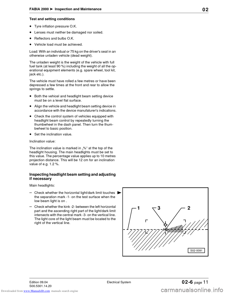
–Check whether the horizontal light/dark limit touches
the separation mark -1- on the test surface when the
low beam light is on .
–Check whether the kink -2- between the left horizontal
part and the ascending right part of the light/dark limit
intersects with the central mark -3- on the vertical line.
The light core of the light beam must be located to the
right of the vertical line.132
S02-0091
Page 66 of 86
Downloaded from www.Manualslib.com manuals search engine FABIA 2000➤Inspection and Maintenance
Electrical SystemEdition 09.04
S00.5301.14.2002-6 page 12 02
♦To easily determine the kink -2-, alternately cover and
uncover the left half of the headlight (in the driving di-
rection) a few times. After this, check the low beam
once again.
♦Once the low beam light has been correctly set the
centre of the light beam of the main beam must be po-
sitioned on the central mark -3-.
♦The adjustment foreseen for the new control screen
also applies for the previous one, which has a 15 ad-
justing line. To avoid incorrect settings disregard the
15 adjusting line.
Other additional headlights:
Additionally fitted headlights must be inspected or set in
compliance with the relevant applicable directives.
Setting the headlight beam
Setting the main beam
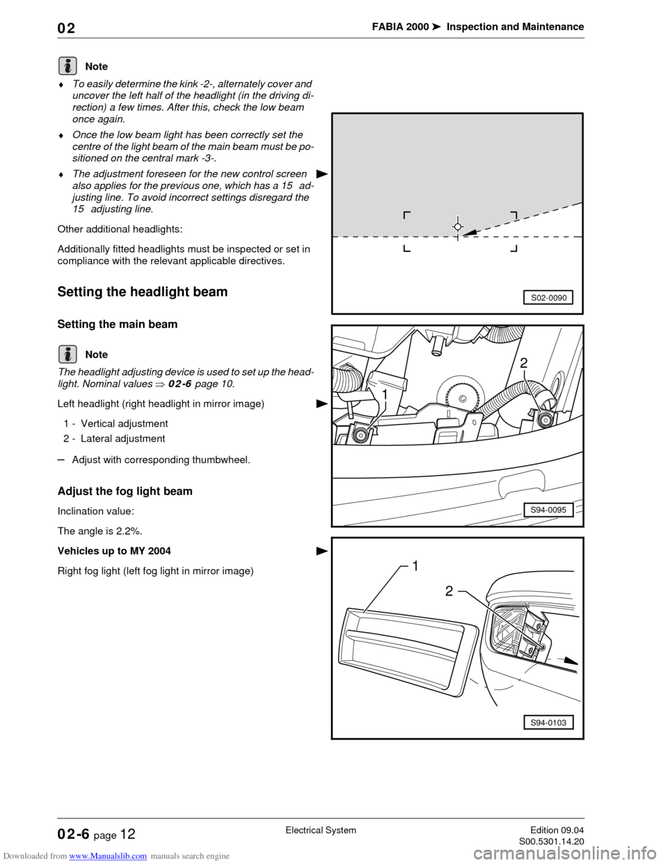
The headlight adjusting device is used to set up the head-
light. Nominal values ⇒02-6 page 10.
Left headlight (right headlight in mirror image)
1 - Vertical adjustment
2 - Lateral adjustment
–Adjust with corresponding thumbwheel.
Adjust the fog light beam
Inclination value:
The angle is 2.2%.
Vehicles up to MY 2004
Right fog light (left fog light in mirror image)
Note
S02-0090
Note2
1
S94-0095
1
2
S94-0103
Page 67 of 86
Downloaded from www.Manualslib.com manuals search engine FABIA 2000➤Inspection and Maintenance
Electrical SystemEdition 09.04
S00.5301.14.2002-6 page 13 02
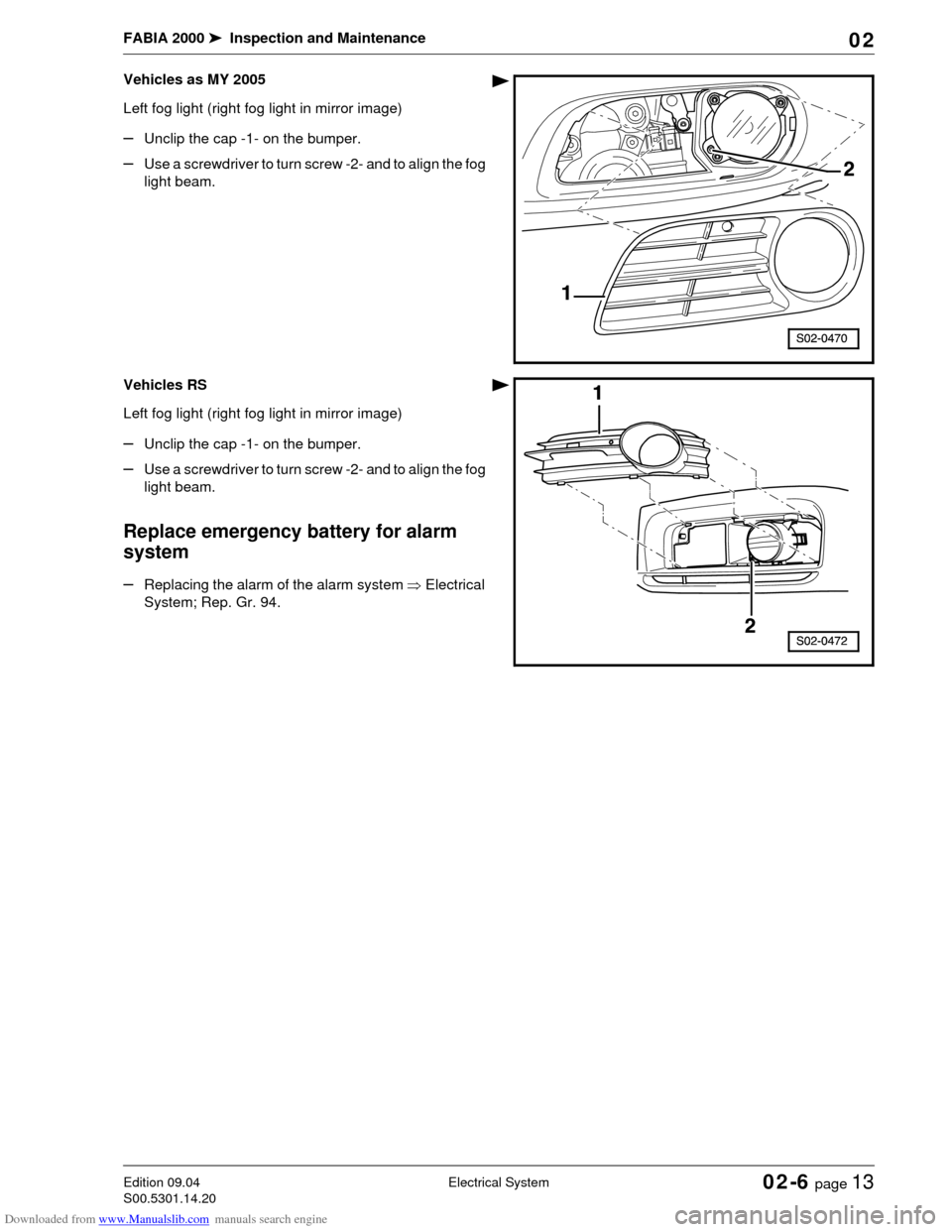
Vehicles as MY 2005
Left fog light (right fog light in mirror image)
–Unclip the cap -1- on the bumper.
–Use a screwdriver to turn screw -2- and to align the fog
light beam.
Vehicles RS
Left fog light (right fog light in mirror image)
–Unclip the cap -1- on the bumper.
–Use a screwdriver to turn screw -2- and to align the fog
light beam.
Replace emergency battery for alarm
system
–Replacing the alarm of the alarm system ⇒Electrical
System; Rep. Gr. 94.
Page 68 of 86

Downloaded from www.Manualslib.com manuals search engine FABIA 2000➤Inspection and Maintenance
Electrical SystemEdition 09.04
S00.5301.14.2002-6 page 14 02
Page 69 of 86
Downloaded from www.Manualslib.com manuals search engine FABIA 2000➤Inspection and Maintenance
BodyEdition 09.04
S00.5301.14.2002-7 page 1 02
02-7 Body
Airbag units: Visual inspection
Inspecting operation of airbag unit
When the ignition is switched on the airbag warning lamp
K75 lights up for approximately 4 seconds. Should the
warning lamp flash again for a further 12 seconds this is
an indication that the front passenger airbag or the side
airbag unit on the front passenger is electronically locked
(valid for vehicles which do not have an airbag switch-off
function).
The warning lamp will go out after 4 seconds for vehicles
which are fitted with an airbag switch-off function and
switching off of the front passenger airbag will be sig-
nalled by the warning lamp „AIRBAG OFF“ in the middle
of the dash panel.
♦If warning lamp K75 does not go out after 4 seconds
and lights up continously there is a fault.
♦If the warning lamp goes out and then lights up again
the control unit is not coded, the wrong control unit has
been fitted or there is a fault.
♦If the airbag warning light K75 flashes constantly, it is
then necessary to replace the airbag control unit J234.
If the warning light indicates a fault, the fault must be
rectified (repair measure) Body Work; Rep. Gr. 01.
Inspecting airbag for external damage
Driver and front passenger airbag units
The logo „AIRBAG“ on the padded boss of the steering
wheel (driver's side) and on the right side of the dash pan-
el (passenger side) indicates that an airbag is fitted.
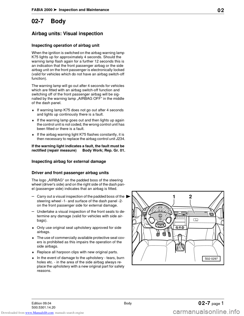
–Carry out a visual inspection of the padded boss of the
steering wheel -1- and surface of the dash panel -2-
on the front passenger side for external damage.
–Undertake a visual inspection of the front seats to de-
termine any damage (valid for vehicles with side air-
bags).
♦Only use original seat upholstery approved for side
airbags.
♦The use of commercially available protective seat cov-
ers is prohibited as this impairs the operation of the
side airbags.
♦Replace all harpoon clips with new original parts.
♦In the event of damage to the upholstery - tears, burn
holes etc. - in the area of the side airbag always re-
place the upholstery with a new original part for safety
reasons.
1
S02-0297
2
Page 70 of 86

Downloaded from www.Manualslib.com manuals search engine FABIA 2000➤Inspection and Maintenance
BodyEdition 09.04
S00.5301.14.2002-7 page 2 02
Do not affix any stickers or cover over the padded boss of
the steering wheel -1- and the foam-lined surface of the
airbag unit on the front passenger side -2- or do not carry
out any modifications to these parts. These parts must
only be cleaned with a dry and slightly moistened cloth.
Inspect key switch for deactivation of
front passenger airbag
–Switch off ignition.
–Turn the key switch for deactivation of front passenger
airbag to the position „OFF“.
When the ignition is switched on the airbag warning lamp
must light up in the front interior light.
–Switch off ignition.
–Turn the key switch for deactivation of front passenger
airbag to the position „ON“.
After the ignition and the front passenger airbag is
switched on, the airbag warning light in the front interior
light must no longer light up after approx. 3 seconds.
Key switch for deactivation of front passenger airbag
must only be turned when ignition is switched off. If the
position of the switch is changed, the airbag control unit
can evaluate a fault; the individual contacts in the switch
make contact during different time intervals and subse-
quently the warning lamp lights up in the dash panel in-
sert (there is no risk of airbag activation).
Check underbody protection and body
paintwork for damage
The inspection of the underbody sealant and paintwork
should cover the following points:
1) undamaged layer of PVC Plastisol
–Vehicle floor
–Wings and wheel housings
–Sills
2) undamaged paintwork
–all body joints
–surround of windscreen
–surround of rear window
–flange of inner surfaces of engine hood
–horizontal and vertical painted surfaces
–Connection of the roof in the area of the luggage com-
partment lid
It is essential to rectify any defects found!
Note
Note