check engine SKODA FABIA 2014 2.G / 5J Owner's Guide
[x] Cancel search | Manufacturer: SKODA, Model Year: 2014, Model line: FABIA, Model: SKODA FABIA 2014 2.G / 5JPages: 197, PDF Size: 13.56 MB
Page 143 of 197
Clear water is not sufficient to intensively clean the windscreen and head-
lights. We recommend using clean washing water together with the screen
cleaner from the range of ŠKODA Original Accessories (in winter additionally
with antifreeze) which is capable of removing stubborn dirt.
The washing water should always be mixed with antifreeze in winter even if
the vehicle has heated windscreen washer nozzles.
Under exceptional circumstances, methylated spirits can also be used if no
screen cleaner with antifreeze is available. The concentration of methylated
spirits must not be more than 15 %. The freeze protection at this concentration
is sufficient only to -5 °C.
CAUTION
■ Under no circumstances must radiator antifreeze or other additives be added
to the windscreen washer fluid.■
If the vehicle is fitted with a headlight cleaning system, only cleaning prod-
ucts which do not attack the polycarbonate coating of the headlights must be
added to the windscreen washer fluid.
■
Do not remove the filter from the windscreen washer fluid reservoir when re-
plenishing it with liquid otherwise the liquid transportation system can be con-
taminated, which can cause the windscreen washer system to malfunction.
Engine oil
Introduction
This chapter contains information on the following subjects:
Specifications and capacity
141
Checking the oil level
142
Replenishing
143
Changing
143
The engine has been factory-filled with a high-grade oil that can be use
throughout the year - except in extreme climate zones.
Engine oils are the subject of continuous further development. Thus the infor-
mation stated in this Owner's Manual is only correct at the time of publication.
ŠKODA Service Partners are informed about the latest changes by the manu-
facturer. We therefore recommend that you have the oil changed by a ŠKODA
Service Partner.
The specifications (VW standards) stated in the following can be indicated sep-
arately or together with other specifications on the bottle.
The oil capacities include oil filter change. Check the oil level when filling; do
not over fill. The oil level must be between the markings » page 142.WARNING■
The engine compartment of your car is a hazardous area. While working in
the engine compartment, be sure to observe the following warn-
ings » page 138 .■
Do not continue your journey if for some reason it is not possible to top
up the engine oil under the current conditions. Switch off the engine and
seek assistance from a specialist garage.
■
Do not drive on if the oil level is above range
A
» Fig. 128 on page 142 .
Switch off the engine and seek assistance from a specialist garage.
CAUTION
Do not pour any additives into the engine oil – there is a risk of serious engine
damage.
Note
■ Before a long drive we recommend that you purchase and carry with you en-
gine oil which complies with the specification for your vehicle.■
We recommend that you use oils from ŠKODA Original Accessories.
■
You must wash yourself thoroughly if your skin has come into contact with
oil.
Specifications and capacity
Read and observe
and on page 141 first.
Specifications and capacity (in l) for vehicles with flexible service intervals
Petrol enginesSpecificationCapacity1.2 litres/44 kWVW 503 00, VW 504 002.81.2 l/51 kWVW 503 00, VW 504 002.81.4 l/63 kWVW 503 00, VW 504 003.21.4 l/132 kW TSIVW 504 003.61.2 l/63 kW TSIVW 504 003.91.2 l/77 kW TSIVW 504 003.9 141Inspecting and replenishing
Page 144 of 197
Diesel enginesa)SpecificationCapacity1.2 l/55 kW TDI CR DPFVW 507 004.31.6 l/55 kW TDI CR DPFVW 507 004.31.6 l/66 kW TDI CR DPFVW 507 004.31.6 l/77 kW TDI CR DPFVW 507 004.3a)
Engine oil VW 505 01 can optionally be used in diesel engines
without a DPF.
Specifications and capacity (in l) for vehicles with fixed service intervals
Petrol enginesSpecificationCapacity1.2 litres/44 kWVW 501 01, VW 502 002.81.2 l/51 kWVW 501 01, VW 502 002.81.4 l/63 kWVW 501 01, VW 502 003.21.6 l/77 kWVW 501 01, VW 502 003.61.4 l/132 kW TSIVW 502 003.61.2 l/63 kW TSIVW 502 003.91.2 l/77 kW TSIVW 502 003.9
If the oils specified above are not available, oils according to ACEA A2 or
ACEA A3 can be used once for refilling.
Diesel engines a)SpecificationCapacity1.2 l/55 kW TDI CR DPFVW 507 004.31.6 l/55 kW TDI CR DPFVW 507 004.31.6 l/66 kW TDI CR DPFVW 507 004.31.6 l/77 kW TDI CR DPFVW 507 004.3a)
Engine oil VW 505 01 can optionally be used in diesel engines
without DPF
If the oils specified above are not available, oils according to ACEA B3 or
ACEA B4 can be used once for refilling.
CAUTION
Only the above-mentioned oils can be used on vehicles with flexible service in-
tervals. We recommend always refilling with oil of the same specification since
this will maintain the properties of the oil. In exceptional cases, a maximum of
0.5 l of specification VW 502 00 (only for petrol engines) or specification
VW 505 01 (only for diesel engines) engine oil can be used to refill once. Other
engine oils must not be used - there is risk of engine damage.Checking the oil levelFig. 128
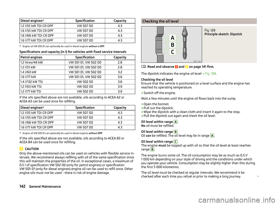
Principle sketch: Dipstick
Read and observe and on page 141 first.
The dipstick indicates the engine oil level » Fig. 128.
Checking the oil level
Ensure that the vehicle is positioned on a level surface and the engine has
reached its operating temperature.
›
Switch off the engine.
Wait a few minutes until the engine oil flows back into the sump.
›
Open the bonnet.
›
Pull out the dipstick.
›
Wipe the dipstick with a clean cloth and insert it again to the stop.
›
Pull the dipstick out again and check the oil level.
Oil level within range
A
No oil must be refilled.
Oil level within range
B
Oil can be refilled. The oil level may lie in range
A
.
Oil level within range
C
The engine must be topped up with oil so that the oil level at least reaches
range
B
.
The engine burns some oil. The oil consumption may be as much as 0.5 l/
1 000 km depending on your style of driving and the conditions under which
you operate your vehicle. Consumption may be slightly higher than this during
the first 5 000 kilometres.
The oil level must be checked at regular intervals. We recommend it be
checked after each time you refuel or prior to making a long journey.
142General Maintenance
Page 145 of 197
We recommend maintaining the oil level within the range A, but not above , if
the engine has been operating at high loads, for example, during a lengthy
motorway trip during the summer months, towing a trailer or negotiating a
high mountain pass.
The warning light in the instrument cluster will indicate whether the oil level is
too low » page 36 ,
Engine oil . Check the oil level using the dipstick as
soon as possible. Add oil accordingly.
CAUTION
■ Always check the oil level on vehicles with the 1.2 l/44 kW engine when the
engine is cold. Otherwise the measuring result is incorrect und oil could be in-
correctly replenished - risk of engine damage!■
The oil level must never be above the
A
range » Fig. 128 – there is a risk of
damaging the exhaust system.
Replenishing
Read and observe
and on page 141 first.
›
Check the oil level » page 142.
›
Unscrew the cap of the engine oil filler opening » Fig. 126 on page 140 .
›
Replenish the oil in portions of 0.5 litres in accordance with the correct speci-
fications » page 141 .
›
Check the oil level » page 142.
›
Carefully screw on the oil filler opening cap and push the dipstick in fully.
Changing
Read and observe
and on page 141 first.
The engine oil must be changed according to prescribed service intervals or ac-cording to the » Service plan service interval display.
Coolant
Introduction
This chapter contains information on the following subjects:
Capacity
144
Checking the coolant level
144
Replenishing
144The coolant consists of water with a concentration of coolant additive. This mixture guarantees antifreeze protection, protects the cooling/heater system
against corrosion and prevents the formation of scale.
Vehicles exported to countries with a mild climate are already factory-filled
with a coolant which offers antifreeze protection down to about -25 ℃. In
these countries the concentration of coolant additive should be at least 40 %.
Vehicles exported to countries with a cold climate are already factory-filled
with a coolant which offers antifreeze protection down to about -35 °C. In
these countries the concentration of coolant additive should be at least 50 %.
If a higher concentration of antifreeze is required for climatic reasons, the
amount of coolant additive can only be increased up to a maximum of 60 %
(antifreeze protection down to approx. -40 °C).
When refilling, only use the same antifreeze identified on the coolant expan-
sion vessel » Fig. 129 on page 144 .WARNING■
The engine compartment of your car is a hazardous area. While working in
the engine compartment, be sure to observe the following warn-
ings » page 138 .■
Do not continue your journey if for some reason it is not possible to top
up the coolant under the current conditions. Switch off the engine and
seek assistance from a specialist garage.
CAUTION
■ The amount of coolant additive in the coolant must never be allowed to fall
below 40 %.■
Over 60 % coolant additive in the coolant reduces the antifreeze protection
and coolant effectiveness.
■
A coolant additive that does not comply with the correct specifications can
significantly reduce the corrosion protection.
■
Any faults resulting from corrosion may cause a loss of coolant and can con-
sequently result in major engine damage!
■
Do not fill the coolant above the mark
A
» Fig. 129 on page 144 .
■
We recommend that you visit a specialist garage if a fault causes the engine
to overheat, otherwise serious engine damage may occur.
■
Additional headlights and other attached components in front of the air inlet
impair the cooling efficiency of the coolant.
■
Never cover the radiator - there is a risk of the engine overheating.
143Inspecting and replenishing
Page 146 of 197
CapacityRead and observe
and on page 143 first.
Coolant capacity (in litres) 1)
Petrol enginesCapacity1.2 litres/44 kW5.51.2 l/51 kW5.51.2 l/63 kW TSI7.71.2 l/77 kW TSI7.71.4 l/63 kW5.51.4 l/132 kW TSI6.61.6 l/77 kW5.5Diesel enginesCapacity1.2 l/55 kW TDI CR DPF6.61.6 l/55 kW TDI CR DPF8.41.6 l/66 kW TDI CR DPF8.41.6 l/77 kW TDI CR DPF8.4
Checking the coolant level
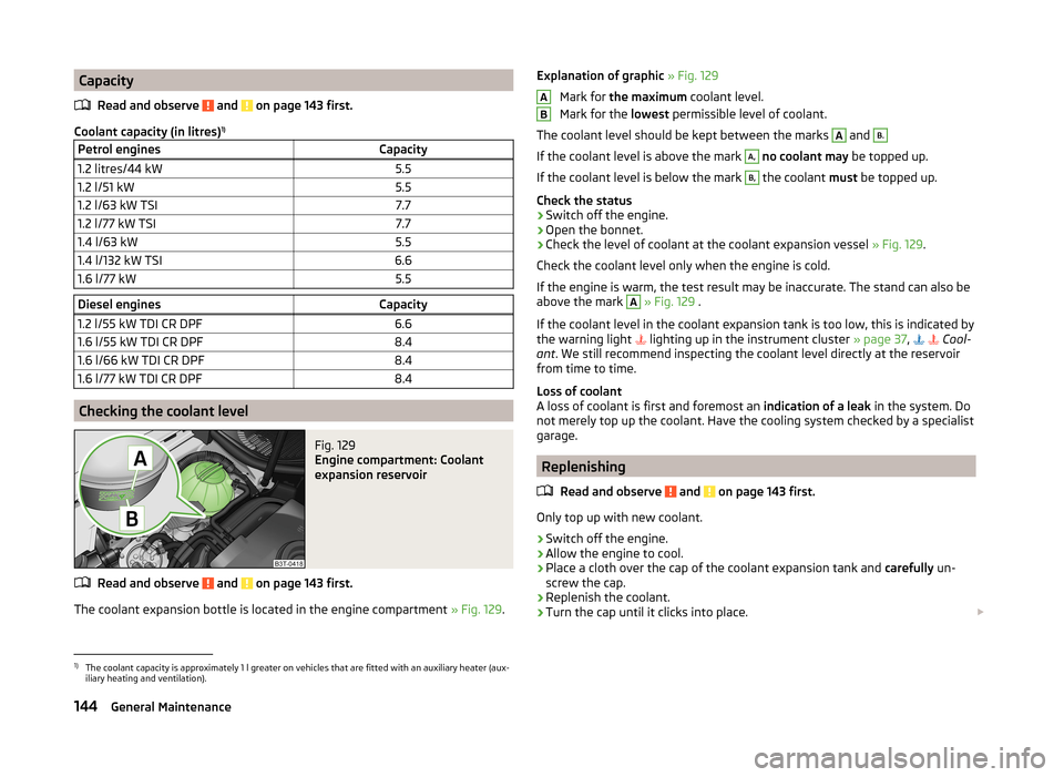
Fig. 129
Engine compartment: Coolant
expansion reservoir
Read and observe and on page 143 first.
The coolant expansion bottle is located in the engine compartment » Fig. 129.
Explanation of graphic » Fig. 129
Mark for the maximum coolant level.
Mark for the lowest permissible level of coolant.
The coolant level should be kept between the marks A
and
B.
If the coolant level is above the mark
A,
no coolant may be topped up.
If the coolant level is below the mark
B,
the coolant must be topped up.
Check the status
›
Switch off the engine.
›
Open the bonnet.
›
Check the level of coolant at the coolant expansion vessel » Fig. 129.
Check the coolant level only when the engine is cold.
If the engine is warm, the test result may be inaccurate. The stand can also be
above the mark
A
» Fig. 129 .
If the coolant level in the coolant expansion tank is too low, this is indicated by
the warning light lighting up in the instrument cluster
» page 37,
Cool-
ant . We still recommend inspecting the coolant level directly at the reservoir
from time to time.
Loss of coolant
A loss of coolant is first and foremost an indication of a leak in the system. Do
not merely top up the coolant. Have the cooling system checked by a specialist
garage.
Replenishing
Read and observe
and on page 143 first.
Only top up with new coolant.
›
Switch off the engine.
›
Allow the engine to cool.
›
Place a cloth over the cap of the coolant expansion tank and carefully un-
screw the cap.
›
Replenish the coolant.
›
Turn the cap until it clicks into place.
AB1)
The coolant capacity is approximately 1 l greater on vehicles that are fitted with an auxiliary heater (aux-
iliary heating and ventilation).
144General Maintenance
Page 147 of 197
Do not use an alternative additive if the specified coolant is not available in an
emergency. In this case, use just water and have the correct mixing ratio of
water and coolant additive restored by a specialist garage as soon as possible.
Brake fluid
Introduction
This chapter contains information on the following subjects:
Level check
145
Changing
145WARNING■ The engine compartment of your car is a hazardous area. While working in
the engine compartment, be sure to observe the following warn-
ings » page 138 .■
Do not continue your journey if the fluid level has fallen below the MIN
marking » Fig. 130 on page 145 - there is a risk of an accident. Seek help
from a specialist garage.
■
Do not use used brake fluid - the function of the brake system may be im-
paired – there is the risk of an accident.
CAUTION
Brake fluid damages the paintwork of the vehicle.
Note
■ The brake fluid is changed as part of a prescribed inspection service.■We recommend using oils from the ŠKODA Original Accessories range.
Level check
Fig. 130
Engine compartment: Brake fluid
reservoir
Read and observe and on page 145 first.
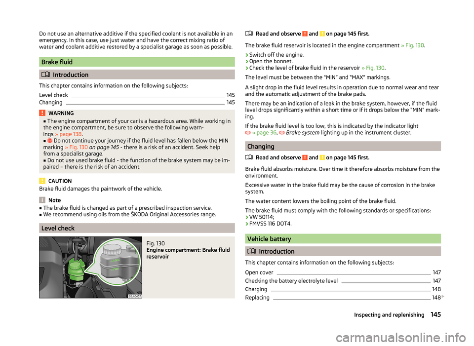
The brake fluid reservoir is located in the engine compartment » Fig. 130.
›
Switch off the engine.
›
Open the bonnet.
›
Check the level of brake fluid in the reservoir » Fig. 130.
The level must be between the “MIN” and “MAX” markings.
A slight drop in the fluid level results in operation due to normal wear and tear
and the automatic adjustment of the brake pads.
There may be an indication of a leak in the brake system, however, if the fluid level drops significantly within a short time or if it drops below the “MIN” mark-
ing.
If the brake fluid level is too low, this is indicated by the indicator light
» page 36 ,
Brake system
lighting up in the instrument cluster.
Changing
Read and observe
and on page 145 first.
Brake fluid absorbs moisture. Over time it therefore absorbs moisture from theenvironment.
Excessive water in the brake fluid may be the cause of corrosion in the brake
system.
The water content lowers the boiling point of the brake fluid.
The brake fluid must comply with the following standards or specifications: › VW 50114;
› FMVSS 116 DOT4.
Vehicle battery
Introduction
This chapter contains information on the following subjects:
Open cover
147
Checking the battery electrolyte level
147
Charging
148
Replacing
148
145Inspecting and replenishing
Page 149 of 197
CAUTION■The vehicle battery must only be disconnected if the ignition is switched off,
otherwise the vehicle's electrical system (electronic components) can be dam-
aged. When disconnecting the battery from the electrical system, first of all
disconnect the negative terminal (-) of the battery, followed by the positive
terminal (+).■
When connecting the battery to the electrical system, first of all connect the
positive terminal (+) of the battery, followed by the negative terminal (-). Under
no circumstances must the battery cables be connected incorrectly – risk of a
cable fire.
■
Ensure that battery acid does not come into contact with the bodywork –
there is a risk of damage to the paintwork.
■
Do not place the battery in direct daylight in order to protect the vehicle bat-
tery housing from the effects of ultra-violet light.
■
If the vehicle has not been driven for more than 3 to 4 weeks, the battery will
discharge. This is because certain electrical components consume electricity
(e. g. control units) also in idle state. Prevent the battery from discharging by
disconnecting the battery's negative terminal (-) or continuously charging the
battery with a very low charging current.
■
If the vehicle is frequently used for making short trips, the vehicle battery
will not have time to charge up sufficiently and may discharge.
For the sake of the environment
A vehicle battery that has been removed is a special type of hazardous waste.
These must be disposed of in accordance with national legal regulations.
Note
You should replace batteries older than 5 years.
Open cover
Fig. 131
Plastic cover of the vehicle bat-
tery
Read and observe and on page 146 first.
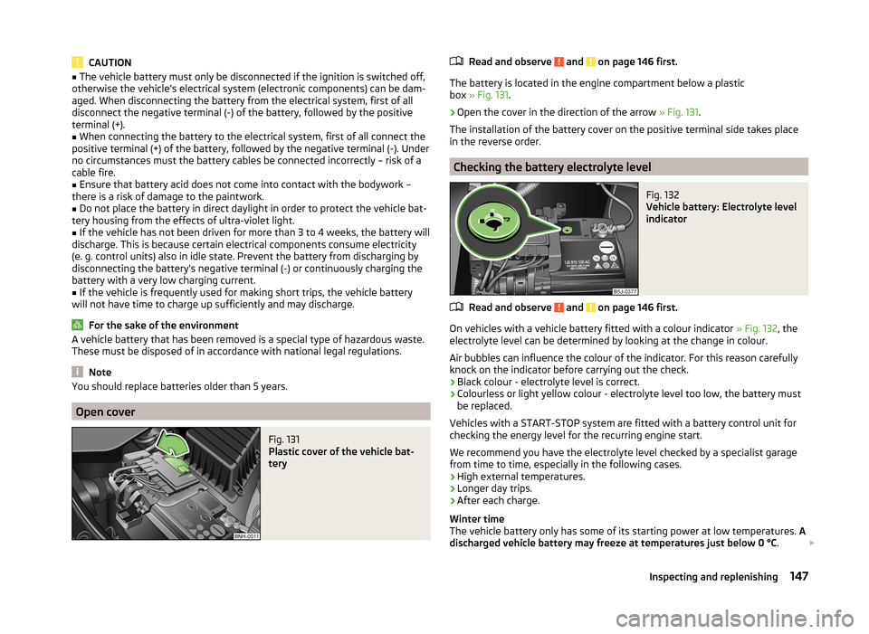
The battery is located in the engine compartment below a plastic
box » Fig. 131 .
›
Open the cover in the direction of the arrow » Fig. 131.
The installation of the battery cover on the positive terminal side takes place
in the reverse order.
Checking the battery electrolyte level
Fig. 132
Vehicle battery: Electrolyte level
indicator
Read and observe and on page 146 first.
On vehicles with a vehicle battery fitted with a colour indicator » Fig. 132, the
electrolyte level can be determined by looking at the change in colour.
Air bubbles can influence the colour of the indicator. For this reason carefully knock on the indicator before carrying out the check.
› Black colour - electrolyte level is correct.
› Colourless or light yellow colour - electrolyte level too low, the battery must
be replaced.
Vehicles with a START-STOP system are fitted with a battery control unit for
checking the energy level for the recurring engine start.
We recommend you have the electrolyte level checked by a specialist garage from time to time, especially in the following cases.
› High external temperatures.
› Longer day trips.
› After each charge.
Winter time
The vehicle battery only has some of its starting power at low temperatures. A
discharged vehicle battery may freeze at temperatures just below 0 °C .
147Inspecting and replenishing
Page 150 of 197
We therefore recommend that you have the battery checked and, if necessary,
recharged by a specialist garage before the start of the winter.
CAUTION
For technical reasons, on vehicles with the description “AGM”, the electrolyte
level cannot be checked.
Note
The battery electrolyte level is also periodically checked by a specialist garage
as part of the Inspection Service.
Charging
Read and observe
and on page 146 first.
A properly charged vehicle battery is essential for reliably starting the engine.
›
Switch off the ignition and all of the electrical components.
›
Only when performing a “quick-charge”, disconnect both battery cables (first
“negative”, then “positive”).
›
Attach the terminal clamps of the charger to the battery terminals (red =
“positive”, black = “negative”).
›
Plug the mains cable of the charger into the power socket and switch the
charger on.
›
Once charging is complete: Switch off the charger and remove the mains ca-
ble from the power socket.
›
Only then disconnect the charger's terminal clamps.
›
Reconnect the cables to the battery (first “positive”, then “negative”).
It is not necessary to disconnect the battery cables if you are recharging the
vehicle battery using low amperages (for example from a mini-charger). Refer
to the charger manufacturer's instructions .
A charging current of 0.1 multiple of the total vehicle battery capacity (or low-
er) must be used until full charging is achieved.
Both cables must be disconnected before charging the battery with high
amperages, known as “ rapid charging”.
The vent plugs of the vehicle battery should not be opened for charging.
WARNING“Quick-charging” the vehicle battery is dangerous and requires a special
charger and specialist knowledge.CAUTIONOn vehicles with the START/STOP system, the pole terminal of the charger
must not be connected directly to the negative terminal of the vehicle battery,
but only to the engine earth » page 166, Jump-starting in vehicles with the
START-STOP system .
Note
We therefore recommend that vehicle batteries be rapid charged by a special-
ist garage.
Replacing
Read and observe
and on page 146 first.
The new vehicle battery must have the same capacity, voltage, current and thesame size as the original battery. Suitable vehicle battery types can be pur-
chased from a specialist garage.
We recommend that the battery is replaced by a specialist garage, where the
new vehicle battery will be installed properly and the original battery will be
disposed of in accordance with national regulations.
Disconnecting or reconnecting
Read and observe
and on page 146 first.
The following functions are initially deactivated or are no longer able to oper-
ate faultlessly after the vehicle battery has been disconnected and reconnec-
ted.
OperationOperating measureElectrical power window (operational faults)» page 53Enter the radio/navigation system code
number» User manual of the radio
or » user manual of the naviga-
tion systemSetting the clock» page 28Data in the multifunction display are de-
leted.» page 29
Note
We recommend having the vehicle checked by a specialist garage to ensure
the full functionality of all electrical systems.148General Maintenance
Page 162 of 197
WARNING (Continued)■Secure the base plate of the lifting jack with suitable means to prevent
possible moving. A soft and slippery ground under the base plate may move
the lifting jack, causing the vehicle to fall down. It is therefore always nec-
essary to place the lifting jack on a solid surface or use a wide and stable
base. Use a non-slip base (e.g. a rubber foot mat) if the surface is smooth,
such as cobbled stones, tiled floor, etc.■
Only attach the lifting jack to the attachment points provided for this pur-
pose.
■
Always raise the vehicle with the doors closed.
■
Never position any body parts, such as arms or legs under the vehicle,
while the vehicle is raised with a lifting jack.
■
Never start the engine with the vehicle sitting on the raised jack – there
is a risk of injury.
WARNINGInformation on the wheel bolts■The wheel bolts must be clean and must turn easily. Never treat them
with grease or oil.■
The prescribed tightening torque of the wheel bolts for steel and light al-
loy wheels is 120 Nm.
■
If the wheel bolts are tightened to a too low tightening torque, the rim
can come loose when the car is moving – risk of accident! A tightening tor-
que which is too high can damage the bolts and threads and this can result
in permanent deformation of the contact surfaces on the rim.
■
In case of incorrect treatment of the wheel bolts, the wheel can loosen
when the car is moving – risk of accident!
Note
The national legal requirements must be observed when changing a wheel.
Preparation
Read and observe
on page 159 first.
Always change a wheel on a level surface as far as possible.
The following steps must be carried out before actually changing the wheel:
›
Have all the occupants get out. The passengers should not stand on the
road (instead they should remain behind a crash barrier, for instance) while
the wheel is being changed.
› Switch off the engine.›Move the gearshift lever into
Neutral or move the selector lever for the auto-
matic gearbox into position P.›
Apply the handbrake firmly.
›
Uncouple any trailer.
›
Remove the vehicle tool kit » page 159 and the spare wheel » page 155 ,
Spare and back-up wheel from the boot.
Changing a wheel
Read and observe
on page 159 first.
›
Remove the full wheel trim » page 156 or caps » page 156 .
›
First of all slacken the anti-theft wheel bolt and then the other wheel
bolts » page 161 .
›
Jack up the vehicle until the wheel that needs changing is clear of the
ground » page 161 .
›
Unscrew the wheel bolts and place them on a clean surface (cloth, paper,
etc.).
›
Remove the wheel carefully.
›
Attach the spare wheel and slightly screw on the wheel bolts.
›
Lower the vehicle.
›
Tighten the opposite wheel bolts alternately (cross-wise) with the wheelwrench. Tighten the anti-theft wheel bolt last » page 161.
›
Reinstall the wheel trim/wheel trim cap or the caps.
Note
■
All bolts must be clean and must turn easily.■Under no circumstances grease or oil the wheel bolts!■
When fitting unidirectional tyres, ensure that the direction of rotation is cor-
rect » page 154 , Unidirectional tyres .
Subsequent steps
Read and observe
on page 159 first.
The following steps must also be performed after changing the wheel.
›
Stow and attach the replaced wheel in the spare wheel well using a special
screw » page 155 , Spare and back-up wheel .
›
Stow the tool kit in the space provided and secure using the strap.
›
Check the tyre pressure on the installed spare wheel as soon as possible.
160Do-it-yourself
Page 165 of 197
WARNING■A tyre filled with sealant has the same driving characteristics as a stand-
ard tyre.■
Do not travel faster than 80 km/h.
■
Avoid accelerating at full throttle, sharp braking and fast cornering.
■
Check the tyre pressure after driving for 10 minutes.
■
The sealant is hazardous to heath. Remove immediately if it comes into
contact with the skin.
For the sake of the environment
Used sealant or sealant whose expiry date has passed must be disposed of in
accordance with environmental protection regulations.
Note
■ Observe the manufacturer's usage instructions for the breakdown kit.■A new bottle of sealant can be purchased from ŠKODA Original Parts.■
Immediately replace the wheel that was repaired using the breakdown kit or
consult a specialist garage about repair possibilities.
Breakdown kit
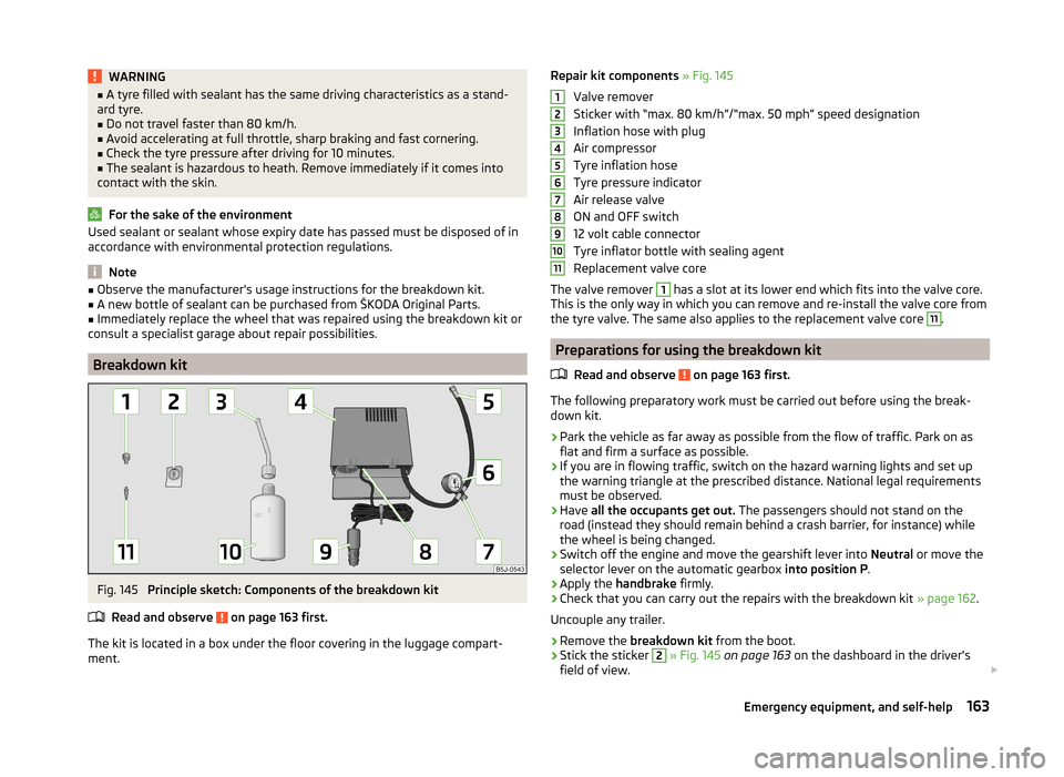
Fig. 145
Principle sketch: Components of the breakdown kit
Read and observe
on page 163 first.
The kit is located in a box under the floor covering in the luggage compart-
ment.
Repair kit components » Fig. 145
Valve remover
Sticker with “max. 80 km/h”/“max. 50 mph” speed designation
Inflation hose with plug
Air compressor
Tyre inflation hose
Tyre pressure indicator
Air release valve
ON and OFF switch
12 volt cable connector
Tyre inflator bottle with sealing agent
Replacement valve core
The valve remover 1
has a slot at its lower end which fits into the valve core.
This is the only way in which you can remove and re-install the valve core from
the tyre valve. The same also applies to the replacement valve core
11
.
Preparations for using the breakdown kit
Read and observe
on page 163 first.
The following preparatory work must be carried out before using the break-
down kit.
›
Park the vehicle as far away as possible from the flow of traffic. Park on as
flat and firm a surface as possible.
›
If you are in flowing traffic, switch on the hazard warning lights and set up
the warning triangle at the prescribed distance. National legal requirements
must be observed.
›
Have all the occupants get out. The passengers should not stand on the
road (instead they should remain behind a crash barrier, for instance) while
the wheel is being changed.
›
Switch off the engine and move the gearshift lever into Neutral or move the
selector lever on the automatic gearbox into position P.
›
Apply the handbrake firmly.
›
Check that you can carry out the repairs with the breakdown kit » page 162.
Uncouple any trailer.
›
Remove the breakdown kit from the boot.
›
Stick the sticker
2
» Fig. 145 on page 163 on the dashboard in the driver's
field of view.
1234567891011163Emergency equipment, and self-help
Page 166 of 197
›Do not remove the foreign body, e.g. screw or nail, from the tyre.›Unscrew the valve cap.›
Use the valve remover
1
to unscrew the valve core and place it on a clean
surface (rag, paper, etc.).
Sealing and inflating the tyre
Read and observe
on page 163 first.
Sealing
›
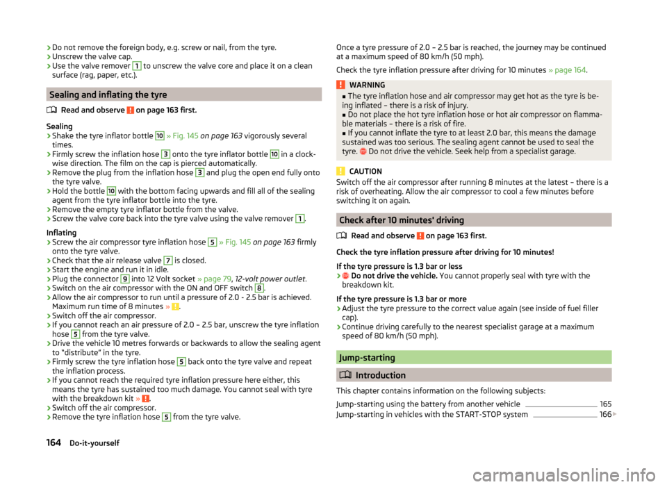
Shake the tyre inflator bottle
10
» Fig. 145 on page 163 vigorously several
times.
›
Firmly screw the inflation hose
3
onto the tyre inflator bottle
10
in a clock-
wise direction. The film on the cap is pierced automatically.
›
Remove the plug from the inflation hose
3
and plug the open end fully onto
the tyre valve.
›
Hold the bottle
10
with the bottom facing upwards and fill all of the sealing
agent from the tyre inflator bottle into the tyre.
›
Remove the empty tyre inflator bottle from the valve.
›
Screw the valve core back into the tyre valve using the valve remover
1
.
Inflating
›
Screw the air compressor tyre inflation hose
5
» Fig. 145 on page 163 firmly
onto the tyre valve.
›
Check that the air release valve
7
is closed.
›
Start the engine and run it in idle.
›
Plug the connector
9
into 12 Volt socket » page 79, 12-volt power outlet .
›
Switch on the air compressor with the ON and OFF switch
8
.
›
Allow the air compressor to run until a pressure of 2.0 - 2.5 bar is achieved.
Maximum run time of 8 minutes » .
›
Switch off the air compressor.
›
If you cannot reach an air pressure of 2.0 – 2.5 bar, unscrew the tyre inflation
hose
5
from the tyre valve.
›
Drive the vehicle 10 metres forwards or backwards to allow the sealing agent
to “distribute” in the tyre.
›
Firmly screw the tyre inflation hose
5
back onto the tyre valve and repeat
the inflation process.
›
If you cannot reach the required tyre inflation pressure here either, this
means the tyre has sustained too much damage. You cannot seal with tyre with the breakdown kit »
.
›
Switch off the air compressor.
›
Remove the tyre inflation hose
5
from the tyre valve.
Once a tyre pressure of 2.0 – 2.5 bar is reached, the journey may be continued
at a maximum speed of 80 km/h (50 mph).
Check the tyre inflation pressure after driving for 10 minutes » page 164.WARNING■
The tyre inflation hose and air compressor may get hot as the tyre is be-
ing inflated – there is a risk of injury.■
Do not place the hot tyre inflation hose or hot air compressor on flamma-
ble materials – there is a risk of fire.
■
If you cannot inflate the tyre to at least 2.0 bar, this means the damage
sustained was too serious. The sealing agent cannot be used to seal the
tyre.
Do not drive the vehicle. Seek help from a specialist garage.
CAUTION
Switch off the air compressor after running 8 minutes at the latest – there is a
risk of overheating. Allow the air compressor to cool a few minutes before
switching it on again.
Check after 10 minutes' driving
Read and observe
on page 163 first.
Check the tyre inflation pressure after driving for 10 minutes!
If the tyre pressure is 1.3 bar or less
›
Do not drive the vehicle. You cannot properly seal with tyre with the
breakdown kit.
If the tyre pressure is 1.3 bar or more
›
Adjust the tyre pressure to the correct value again (see inside of fuel filler
cap).
›
Continue driving carefully to the nearest specialist garage at a maximum speed of 80 km/h (50 mph).
Jump-starting
Introduction
This chapter contains information on the following subjects:
Jump-starting using the battery from another vehicle
165
Jump-starting in vehicles with the START-STOP system
166
164Do-it-yourself