fog light SKODA FABIA 2014 2.G / 5J Owner's Manual
[x] Cancel search | Manufacturer: SKODA, Model Year: 2014, Model line: FABIA, Model: SKODA FABIA 2014 2.G / 5JPages: 197, PDF Size: 13.56 MB
Page 37 of 197
The following message is shown in the MAXI DOT display.Gearbox overheated. Stop. Log book!
Stop the vehicle, switch off the engine, and wait until the
icon goes out –
there is a risk of gearbox damage. You can continue your journey as soon as
the icon disappears.WARNINGIf you have to stop for technical reasons, park the vehicle at a safe distance
from the traffic, switch off the engine and activate the hazard warning light
system » page 59 .
Note
■
Warning messages shown in the MAXI DOT display must be confirmed with
button B » Fig. 24 on page 33 to call up the main menu.■
As long as the operational faults are not rectified, the symbols are always in-
dicated again. After they are displayed for the first time, the symbols continue
to be indicated without any extra messages for the driver.
Warning lights
Introduction
This chapter contains information on the following subjects:
Handbrake
35
Brake system
36
Seat belt warning light
36
Generator
36
OPen door
36
Engine oil
36
Coolant
37
Power steering
38
Electronic Stability Control (ESC)
38
Traction Control System (ASR)
38
Antilock brake system (ABS)
38
The rear fog light
39
Bulb failure
39
Exhaust inspection system
39
Glow plug system (diesel engine)
39 EPC fault light (petrol engine)39 Diesel particulate filter (diesel engine)39
Fuel reserve
40
Airbag system
40
Tyre pressure
41
Windscreen washer fluid level
41
Traction control (TCS) switched off
41
Turn signal system
41
Low beam
41
Fog lights
41
Cruise control system
41
Selector lever lock
42
Main beam
42
The warning lights show certain functions/faults and may be accompanied by
audible signals.
WARNING■ If illuminated warning lights and the corresponding descriptions and
warning notes are not observed, this may result in severe injuries or major
vehicle damage.■
The engine compartment of your car is a hazardous area. There is a risk of
injuries, scalding, accidents and fire when working in the engine compart-
ment, e.g. inspecting and replenishing oil and other fluids. It is essential to
observe safety notes » page 138, Engine compartment .
Handbrake
Read and observe
on page 35 first.
The warning light comes on if the handbrake is applied. An audible warning
is also given if you drive the vehicle for at least 3 seconds at a speed of more
than 6 km/h.
The following message is shown in the MAXI DOT display. Release parking brake!
35Instruments and Indicator Lights
Page 41 of 197
The following message is shown in the MAXI DOT display.Error: ABS
The vehicle will only be braked by the normal brake system without the ABS.
Seek help from a specialist garage.WARNING■ If you have to stop for technical reasons, then park the vehicle at a safe
distance from the traffic, switch off the engine and activate the hazard
warning light system » page 59.■
If the warning light
» page 36 is displayed simultaneously with the ABS
warning light
,
do not continue your journey! Seek help from a special-
ist garage.
■
A fault to the ABS system or the braking system can increase the vehi-
cle's braking distance – there is a risk of accident.
The rear fog light
Read and observe
on page 35 first.
The warning light comes on when the rear fog lights are operat-
ing » page 58 .
Bulb failure
Read and observe
on page 35 first.
The warning light comes on if a bulb is faulty:
› within a few seconds of the ignition being switched on;
› when a light with a defective bulb is switched on.
The following message may be shown in the MAXI DOT display, for example. INFORMATION Check front right low beam!
Note
The rear side lights and the licence plate lighting have several light bulbs. The
indicator light only lights up if all light bulbs of the licence plate lighting or
the parking light (in one rear light) are defective. For this reason, regular check
that these light bulbs are working correctly. Exhaust inspection system
Read and observe
on page 35 first.
If the warning light
lights up, there is a fault in the exhaust inspection sys-
tem. The engine control unit allows the vehicle to run in emergency mode.
Seek help from a specialist garage.
Glow plug system (diesel engine)
Read and observe
on page 35 first.
The warning light comes on after the ignition has been switched on. The
engine can be started immediately after the pre-glow warning light goes out.
There is a fault in the glow plug system if the warning light
does not come
on at all or lights up continuously .
If the warning light begins to
flash while driving, a fault exists in the engine
control. The engine control unit allows the vehicle to run in emergency mode.
Seek help from a specialist garage.
EPC fault light (petrol engine)
Read and observe
on page 35 first.
If the warning light comes on or begins to flash while driving, a fault exists
in the engine control unit. The engine control unit allows the vehicle to run in
emergency mode.
Seek help from a specialist garage.
Diesel particulate filter (diesel engine)
Read and observe
on page 35 first.
The diesel particulate filter separates the soot particles from the exhaust. The soot particles collect in the diesel particulate filter where they are burnt on a
regular basis.
The warning light comes on if soot has accumulated in the filter.
39Instruments and Indicator Lights
Page 43 of 197
WARNINGWhen a fault of the airbag system occurs, there is a risk of the system not
being triggered in the event of an accident. Therefore, this is to be checked
immediately by a specialized company.
Tyre pressure
Read and observe
on page 35 first.
The warning light lights up, if there is a substantial drop in inflation pres-
sure in one of the tyres. Check and adjust the pressure in all tyres.
If the indicator light flashes, there is a fault in the tyre pressure monitoring
system. Stop the car, turn the ignition off and on again.
If the warning light flashes again after re-starting the engine, then the help
of a professional service provider is to be sought.
Further information » page 154, Tyre pressure monitor .
WARNINGIf you have to stop for technical reasons, then park the vehicle at a safe
distance from the traffic, switch off the engine and activate the hazard
warning lights system » page 59.
Note
If the battery has been disconnected, the warning light illuminates after the
ignition is switched on. The warning light should go out after driving a short
distance.
Windscreen washer fluid level
Read and observe
on page 35 first.
If the windscreen washer fluid level is too low, the warning light comes on.
The following message is shown in the MAXI DOT display. Top up wash fluid!
Top up with liquid » page 140.
Traction control (TCS) switched off
Read and observe
on page 35 first.
The ASR is switched off by pressing the button » page 115 and the warning
light
illuminates.
The following message is shown in the MAXI DOT display.
Traction control (ASR) deactivated.
Turn signal system
Read and observe
on page 35 first.
Either the left or right
warning light flashes depending on the position of
the turn signal lever.
If a turn signal light fails, the warning light flashes at twice its normal rate.
Switching off the hazard warning light system is switched on will cause all of
the turn signal lights as well as both warning lights to flash.
Further information » page 57, Turn signal and main beam lights .
Low beam
Read and observe
on page 35 first.
The warning light comes on when low beam is selected
» page 56.
Fog lights
Read and observe
on page 35 first.
The warning light comes on when the fog lights are operating
» page 58.
Cruise control system
Read and observe
on page 35 first.
The warning light comes on when the cruise control is operat-
ing » page 117 .
41Instruments and Indicator Lights
Page 57 of 197
Emergency operationFig. 39
Point for positioning screwdriver/opening for positioning the key
Read and observe
and on page 53 first.
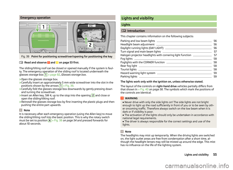
The sliding/tilting roof can be closed or opened manually if the system is faul-
ty. The emergency operation of the sliding roof is located underneath the
glasses storage box
1
» page 82 , Glasses storage box .
›
Open the glasses storage box.
›
Carefully insert an approximately 5 mm wide screwdriver into the slot in the
positions shown by the arrows
1
» Fig. 39 .
›
Carefully fold the glasses storage box downwards by gently pressing down
and turning the screwdriver.
›
Insert an Allen key, SW 4, up to the stop into the opening
2
and close or
open the sliding/tilting roof.
›
Reinstall the glasses storage box by first inserting the plastic plugs and then
pushing the entire part upwards.
Note
It is necessary after each emergency operation (using the Allen key) to move
the sliding/tilting roof into the basic position. This is why the rotary switch
must be set to position A
» Fig. 38 on page 54 and pressed forwards for
about 10 seconds.
Lights and visibility
Lights
Introduction
This chapter contains information on the following subjects:
Parking and low beam lights
56
Headlight beam adjustment
56
Daylight running lights (DAY LIGHT)
56
Turn signal and main beam lights
57
Halogen projector headlights with cornering light function
57
Fog lights
58
Foglights with the CORNER function
58
Rear fog light
58
Tourist lights
58
Hazard warning light system
59
Parking lights
59
The lights work only with the ignition on, unless otherwise stated.
The layout of the controls on right-hand drive vehicles partially differs from
that shown in » Fig. 40 on page 56 . The symbols which mark the positions of
the controls are identical.
WARNING■ Never drive with only the side lights on! The side lights are not bright
enough to light up the road sufficiently in front of you or to be seen by oth-
er oncoming traffic. Therefore always switch on the low beam when it is
dark or if visibility is poor.■
The activation of the lights should only be undertaken in accordance with
national legal requirements.
■
The driver is always responsible for the correct settings and use of the
lights.
Note
The headlights may mist up temporarily. When the driving lights are switched
on, the light outlet areas are free from condensation after a short time, al-
though the headlight lenses may still be misted up around the edge. This mist
has no influence on the life of the lighting system.55Lights and visibility
Page 58 of 197
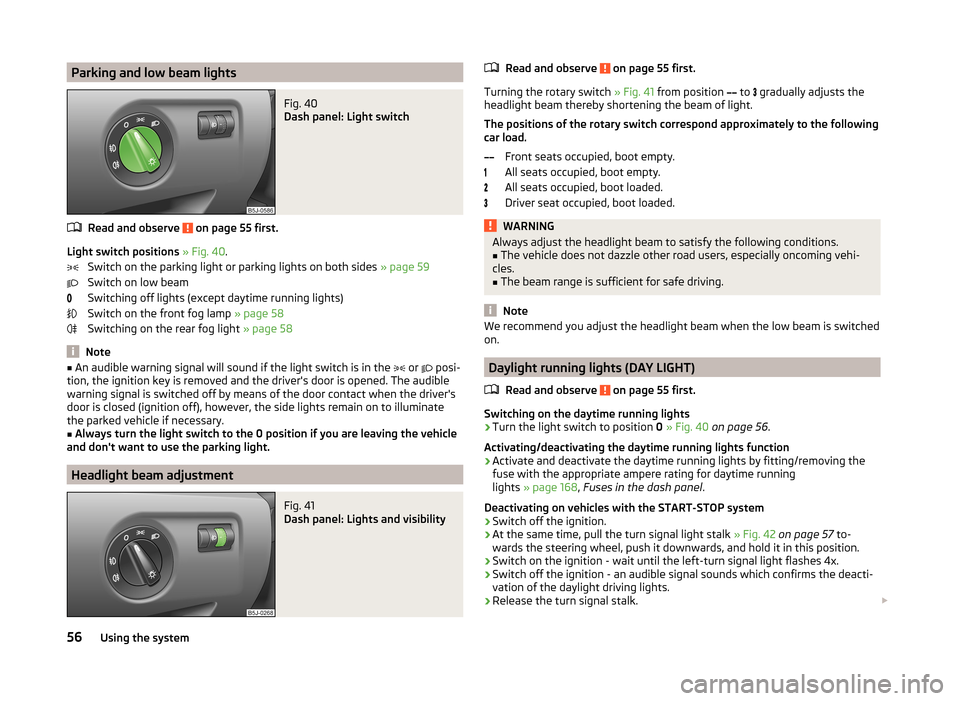
Parking and low beam lightsFig. 40
Dash panel: Light switch
Read and observe on page 55 first.
Light switch positions » Fig. 40 .
Switch on the parking light or parking lights on both sides » page 59
Switch on low beam
Switching off lights (except daytime running lights)
Switch on the front fog lamp » page 58
Switching on the rear fog light » page 58
Note
■
An audible warning signal will sound if the light switch is in the or posi-
tion, the ignition key is removed and the driver's door is opened. The audible
warning signal is switched off by means of the door contact when the driver's
door is closed (ignition off), however, the side lights remain on to illuminate
the parked vehicle if necessary.■
Always turn the light switch to the 0 position if you are leaving the vehicle
and don't want to use the parking light.
Headlight beam adjustment
Fig. 41
Dash panel: Lights and visibility
Read and observe on page 55 first.
Turning the rotary switch » Fig. 41 from position
to
gradually adjusts the
headlight beam thereby shortening the beam of light.
The positions of the rotary switch correspond approximately to the following
car load.
Front seats occupied, boot empty.
All seats occupied, boot empty.
All seats occupied, boot loaded.
Driver seat occupied, boot loaded.
WARNINGAlways adjust the headlight beam to satisfy the following conditions.■The vehicle does not dazzle other road users, especially oncoming vehi-
cles.■
The beam range is sufficient for safe driving.
Note
We recommend you adjust the headlight beam when the low beam is switched
on.
Daylight running lights (DAY LIGHT)
Read and observe
on page 55 first.
Switching on the daytime running lights
›
Turn the light switch to position 0 » Fig. 40 on page 56 .
Activating/deactivating the daytime running lights function
›
Activate and deactivate the daytime running lights by fitting/removing the
fuse with the appropriate ampere rating for daytime running
lights » page 168 , Fuses in the dash panel .
Deactivating on vehicles with the START-STOP system
›
Switch off the ignition.
›
At the same time, pull the turn signal light stalk » Fig. 42 on page 57 to-
wards the steering wheel, push it downwards, and hold it in this position.
›
Switch on the ignition - wait until the left-turn signal light flashes 4x.
›
Switch off the ignition - an audible signal sounds which confirms the deacti-
vation of the daylight driving lights.
›
Release the turn signal stalk.
56Using the system
Page 59 of 197
Activating on vehicles with the START-STOP system›Switch off the ignition.›
At the same time, pull the turn signal light stalk » Fig. 42 on page 57 to-
wards the steering wheel, push it upwards, and hold it in this position.
›
Switch on the ignition - wait until the right-turn signal light flashes 4x.
›
Switch off the ignition - an audible signal sounds which confirms the activa-
tion of the daylight driving lights.
›
Release the turn signal stalk.
On vehicles with separate lights for daylight driving lights in the fog lights or in
the front bumper, the parking lights and the licence plate light do not come on
when activating the function daylight driving lights (neither front nor rear).
If the vehicle is not equipped with separate lights for daylight driving lights,
the combination of the low beam, the parking lights (front and rear) including
the licence plate light is used as daylight driving lights.
Note
In vehicles with separate lights for daylight driving lights (in the bumper below
the main headlights) these lights also serve as side lights.
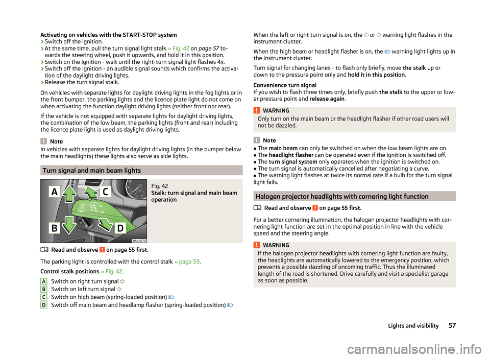
Turn signal and main beam lights
Fig. 42
Stalk: turn signal and main beam
operation
Read and observe on page 55 first.
The parking light is controlled with the control stalk » page 59.
Control stalk positions » Fig. 42 .
Switch on right turn signal
Switch on left turn signal
Switch on high beam (spring-loaded position)
Switch off main beam and headlamp flasher (spring-loaded position)
ABCDWhen the left or right turn signal is on, the
or warning light flashes in the
instrument cluster.
When the high beam or headlight flasher is on, the
warning light lights up in
the instrument cluster.
Turn signal for changing lanes - to flash only briefly, move the stalk up or
down to the pressure point only and hold it in this position.
Convenience turn signal
If you wish to flash three times only, briefly push the stalk to the upper or low-
er pressure point and release again.WARNINGOnly turn on the main beam or the headlight flasher if other road users will
not be dazzled.
Note
■ The main beam can only be switched on when the low beam lights are on.■The headlight flasher can be operated even if the ignition is switched off.■
The turn signal system only operates when the ignition is switched on.
■
The turn signal is automatically cancelled after negotiating a curve.
■
The warning light flashes at twice its normal rate if a bulb for the turn signal
light fails.
Halogen projector headlights with cornering light function
Read and observe
on page 55 first.
For a better cornering illumination, the halogen projector headlights with cor-
nering light function are set in the optimal position in line with the vehicle
speed and the steering angle.
WARNINGIf the halogen projector headlights with cornering light function are faulty,
the headlights are automatically lowered to the emergency position, which
prevents a possible dazzling of oncoming traffic. Thus the illuminated
length of the road is shortened. Drive carefully and visit a specialist garage
as soon as possible.57Lights and visibility
Page 60 of 197
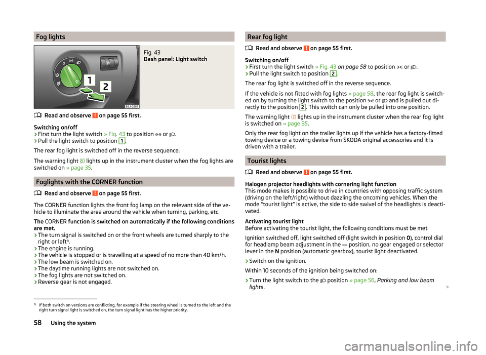
Fog lightsFig. 43
Dash panel: Light switch
Read and observe on page 55 first.
Switching on/off
›
First turn the light switch » Fig. 43 to position
or
.
›
Pull the light switch to position
1
.
The rear fog light is switched off in the reverse sequence.
The warning light lights up in the instrument cluster when the fog lights are
switched on » page 35.
Foglights with the CORNER function
Read and observe
on page 55 first.
The CORNER function lights the front fog lamp on the relevant side of the ve-
hicle to illuminate the area around the vehicle when turning, parking, etc.
The CORNER function is switched on automatically if the following conditions
are met.
› The turn signal is switched on or the front wheels are turned sharply to the
right or left 1)
.
› The engine is running.
› The vehicle is stopped or is travelling at a speed of no more than 40 km/h.
› The low beam is switched on.
› The daytime running lights are not switched on.
› The fog lights are not switched on.
› Reverse gear is not engaged.
Rear fog light
Read and observe
on page 55 first.
Switching on/off
›
First turn the light switch » Fig. 43 on page 58 to position
or
.
›
Pull the light switch to position
2
.
The rear fog light is switched off in the reverse sequence.
If the vehicle is not fitted with fog lights » page 58, the rear fog light is switch-
ed on by turning the light switch to the position
or
and is pulled out di-
rectly to the position
2
. This switch can only be pulled into one position.
The warning light lights up in the instrument cluster when the rear fog light
is switched on » page 35.
Only the rear fog light on the trailer lights up if the vehicle has a factory-fitted
towing device or a towing device from ŠKODA original accessories and it is
driven with a trailer.
Tourist lights
Read and observe
on page 55 first.
Halogen projector headlights with cornering light function
This mode makes it possible to drive in countries with opposing traffic system
(driving on the left/right) without dazzling the oncoming vehicles. When the
mode “tourist light” is active, the side to side swivel of the headlights is deacti-
vated.
Activating tourist light
Before activating the tourist light, the following conditions must be met.
Ignition switched off, light switched off (light switch in position 0), control dial
for headlamp beam adjustment in the position, no gear engaged or selector
lever in the N position (automatic gearbox), tourist light deactivated.
›
Switch on the ignition.
Within 10 seconds of the ignition being switched on:
›
Turn the light switch to the position
» page 56 , Parking and low beam
lights .
1)
If both switch on versions are conflicting, for example if the steering wheel is turned to the left and the
right turn signal light is switched on, the turn signal light has the higher priority.
58Using the system
Page 91 of 197
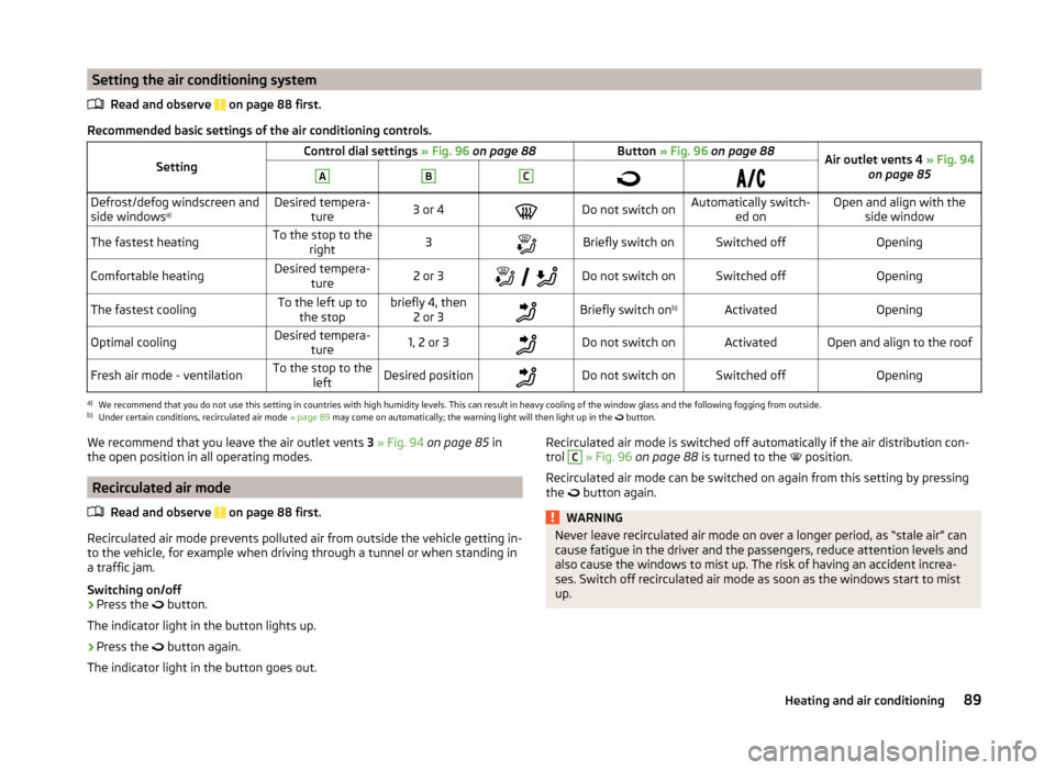
Setting the air conditioning systemRead and observe
on page 88 first.
Recommended basic settings of the air conditioning controls.
SettingControl dial settings » Fig. 96 on page 88Button » Fig. 96 on page 88Air outlet vents 4 » Fig. 94
on page 85ABCDefrost/defog windscreen and
side windows a)Desired tempera-
ture3 or 4Do not switch onAutomatically switch- ed onOpen and align with theside windowThe fastest heatingTo the stop to the right3Briefly switch onSwitched offOpeningComfortable heatingDesired tempera-
ture2 or 3
Do not switch onSwitched offOpeningThe fastest coolingTo the left up to
the stopbriefly 4, then 2 or 3Briefly switch on b)ActivatedOpeningOptimal coolingDesired tempera-
ture1, 2 or 3Do not switch onActivatedOpen and align to the roofFresh air mode - ventilationTo the stop to the leftDesired positionDo not switch onSwitched offOpeninga)
We recommend that you do not use this setting in countries with high humidity levels. This can result in heavy cooling of the window glass and the following fogging from outside.
b)
Under certain conditions, recirculated air mode » page 89 may come on automatically; the warning light will then light up in the
button.
We recommend that you leave the air outlet vents
3 » Fig. 94 on page 85 in
the open position in all operating modes.
Recirculated air mode
Read and observe
on page 88 first.
Recirculated air mode prevents polluted air from outside the vehicle getting in-
to the vehicle, for example when driving through a tunnel or when standing in
a traffic jam.
Switching on/off
›
Press the button.
The indicator light in the button lights up.
›
Press the button again.
The indicator light in the button goes out.
Recirculated air mode is switched off automatically if the air distribution con-
trol C » Fig. 96 on page 88 is turned to the position.
Recirculated air mode can be switched on again from this setting by pressing the
button again.WARNINGNever leave recirculated air mode on over a longer period, as “stale air” can
cause fatigue in the driver and the passengers, reduce attention levels and
also cause the windows to mist up. The risk of having an accident increa-
ses. Switch off recirculated air mode as soon as the windows start to mist
up.89Heating and air conditioning
Page 171 of 197
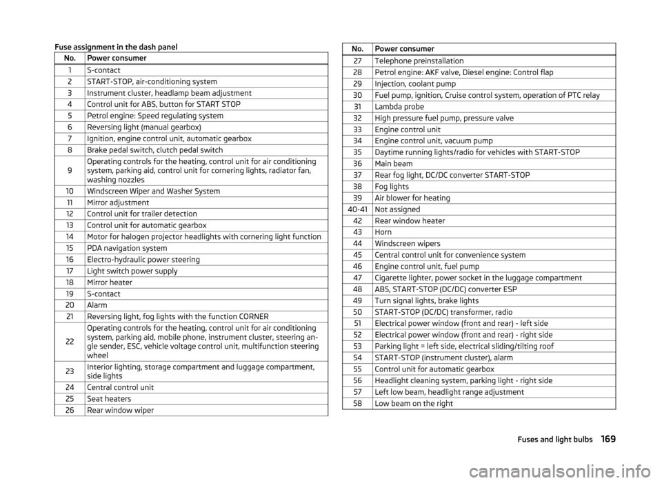
Fuse assignment in the dash panelNo.Power consumer1S-contact2START-STOP, air-conditioning system3Instrument cluster, headlamp beam adjustment4Control unit for ABS, button for START STOP5Petrol engine: Speed regulating system6Reversing light (manual gearbox)7Ignition, engine control unit, automatic gearbox8Brake pedal switch, clutch pedal switch9Operating controls for the heating, control unit for air conditioning
system, parking aid, control unit for cornering lights, radiator fan,
washing nozzles10Windscreen Wiper and Washer System11Mirror adjustment12Control unit for trailer detection13Control unit for automatic gearbox14Motor for halogen projector headlights with cornering light function15PDA navigation system16Electro-hydraulic power steering17Light switch power supply18Mirror heater19S-contact20Alarm21Reversing light, fog lights with the function CORNER
22
Operating controls for the heating, control unit for air conditioning
system, parking aid, mobile phone, instrument cluster, steering an-
gle sender, ESC, vehicle voltage control unit, multifunction steering
wheel23Interior lighting, storage compartment and luggage compartment,
side lights24Central control unit25Seat heaters26Rear window wiperNo.Power consumer27Telephone preinstallation28Petrol engine: AKF valve, Diesel engine: Control flap29Injection, coolant pump30Fuel pump, ignition, Cruise control system, operation of PTC relay31Lambda probe32High pressure fuel pump, pressure valve33Engine control unit34Engine control unit, vacuum pump35Daytime running lights/radio for vehicles with START-STOP36Main beam37Rear fog light, DC/DC converter START-STOP38Fog lights39Air blower for heating40-41Not assigned42Rear window heater43Horn44Windscreen wipers45Central control unit for convenience system46Engine control unit, fuel pump47Cigarette lighter, power socket in the luggage compartment48ABS, START-STOP (DC/DC) converter ESP49Turn signal lights, brake lights50START-STOP (DC/DC) transformer, radio51Electrical power window (front and rear) - left side52Electrical power window (front and rear) - right side53Parking light = left side, electrical sliding/tilting roof54START-STOP (instrument cluster), alarm55Control unit for automatic gearbox56Headlight cleaning system, parking light - right side57Left low beam, headlight range adjustment58Low beam on the right169Fuses and light bulbs
Page 172 of 197
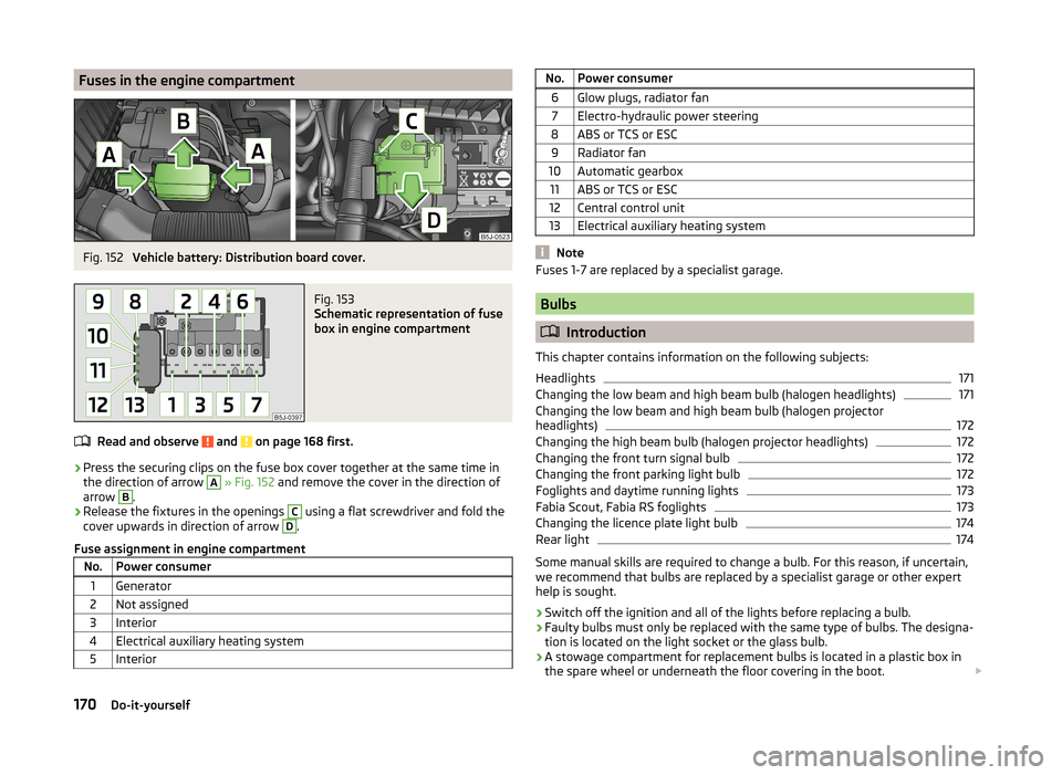
Fuses in the engine compartmentFig. 152
Vehicle battery: Distribution board cover.
Fig. 153
Schematic representation of fuse
box in engine compartment
Read and observe and on page 168 first.
› Press the securing clips on the fuse box cover together at the same time in
the direction of arrow
A
» Fig. 152 and remove the cover in the direction of
arrow
B
.
› Release the fixtures in the openings
C
using a flat screwdriver and fold the
cover upwards in direction of arrow
D
.
Fuse assignment in engine compartment
No.Power consumer1Generator2Not assigned3Interior4Electrical auxiliary heating system5InteriorNo.Power consumer6Glow plugs, radiator fan7Electro-hydraulic power steering8ABS or TCS or ESC9Radiator fan10Automatic gearbox11ABS or TCS or ESC12Central control unit13Electrical auxiliary heating system
Note
Fuses 1-7 are replaced by a specialist garage.
Bulbs
Introduction
This chapter contains information on the following subjects:
Headlights
171
Changing the low beam and high beam bulb (halogen headlights)
171
Changing the low beam and high beam bulb (halogen projector
headlights)
172
Changing the high beam bulb (halogen projector headlights)
172
Changing the front turn signal bulb
172
Changing the front parking light bulb
172
Foglights and daytime running lights
173
Fabia Scout, Fabia RS foglights
173
Changing the licence plate light bulb
174
Rear light
174
Some manual skills are required to change a bulb. For this reason, if uncertain,
we recommend that bulbs are replaced by a specialist garage or other expert
help is sought.
› Switch off the ignition and all of the lights before replacing a bulb.
› Faulty bulbs must only be replaced with the same type of bulbs. The designa-
tion is located on the light socket or the glass bulb.
› A stowage compartment for replacement bulbs is located in a plastic box in
the spare wheel or underneath the floor covering in the boot.
170Do-it-yourself