heating SKODA FABIA 2014 2.G / 5J Owner's Manual
[x] Cancel search | Manufacturer: SKODA, Model Year: 2014, Model line: FABIA, Model: SKODA FABIA 2014 2.G / 5JPages: 197, PDF Size: 13.56 MB
Page 5 of 197
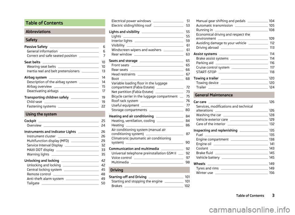
Table of Contents
Abbreviations
Safety
Passive Safety
6
General information
6
Correct and safe seated position
7
Seat belts
10
Wearing seat belts
10
Inertia reel and belt pretensioners
13
Airbag system
14
Description of the airbag system
14
Airbag overview
15
Deactivating airbags
17
Transporting children safely
19
Child seat
19
Fastening systems
22
Using the system
Cockpit
25
Overview
24
Instruments and Indicator Lights
26
Instrument cluster
26
Multifunction display (MFD)
29
Service Interval Display
32
MAXI DOT display
33
Warning lights
35
Unlocking and locking
42
Unlocking and locking
42
Central locking system
45
Remote control
48
Anti-theft alarm system
49
Tailgate
50Electrical power windows51Electric sliding/tilting roof53
Lights and visibility
55
Lights
55
Interior lights
59
Visibility
61
Windscreen wipers and washers
61
Rear window
63
Seats and storage
65
Front seats
65
Rear seats
66
Head restraints
67
Boot
68
Variable loading floor in the luggage
compartment (Fabia Estate)
72
Net partition (Fabia Estate)
73
Bicycle carrier in the luggage compartment
75
Roof rack system
76
Useful equipment
77
Storage compartments
80
Heating and air conditioning
84
Heating, ventilation, cooling
84
Heating
86
Air conditioning system (manual air
conditioning system)
87
Climatronic (automatic air conditioning
system)
90
Communication and multimedia
92
Universal telephone preinstallation GSM II
92
Voice control
97
Multimedia
98
Driving
Starting-off and Driving
101
Starting and stopping the engine
101
Brakes
102Manual gear shifting and pedals104Automatic transmission105
Running in
108
Economical driving and respect the
environment
109
Avoiding damage to your vehicle
112
Driving abroad
113
Assist systems
114
Brake assist systems
114
Parking aid
116
Cruise control system
117
START-STOP
118
Towing a trailer
120
Towing device
120
Trailer
124
General Maintenance
Car care
126
Services, modifications and technical
alterations
126
Washing the car
128
Vehicle exterior care
129
Care of the interior
132
Inspecting and replenishing
135
Fuel
135
Engine compartment
138
Engine oil
141
Coolant
143
Brake fluid
145
Vehicle battery
145
Wheels
149
Tyres and rims
149
Winter use
1563Table of Contents
Page 27 of 197
Using the system
Cockpit
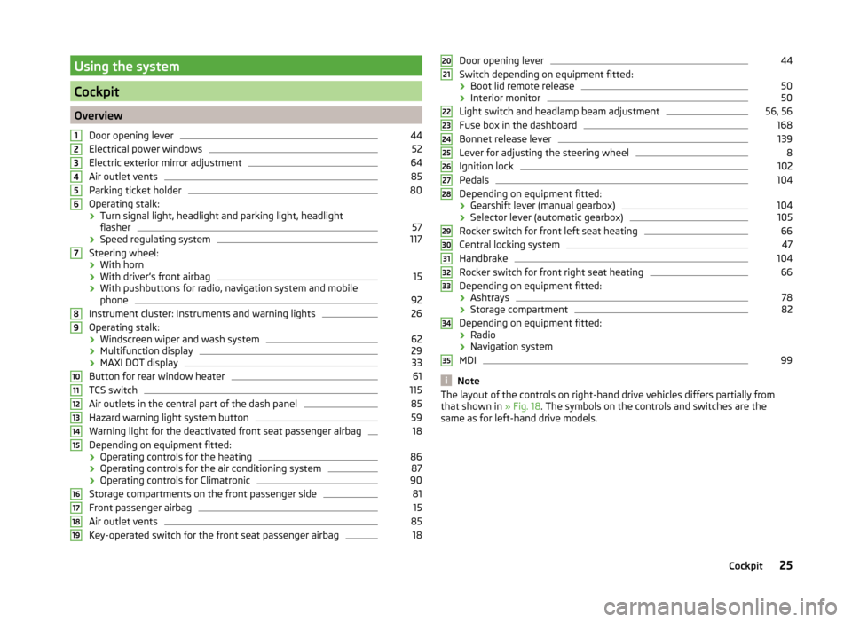
OverviewDoor opening lever
44
Electrical power windows
52
Electric exterior mirror adjustment
64
Air outlet vents
85
Parking ticket holder
80
Operating stalk:
› Turn signal light, headlight and parking light, headlight
flasher
57
› Speed regulating system
117
Steering wheel:
› With horn
› With driver’s front airbag
15
›With pushbuttons for radio, navigation system and mobile
phone
92
Instrument cluster: Instruments and warning lights
26
Operating stalk:
› Windscreen wiper and wash system
62
›Multifunction display
29
›MAXI DOT display
33
Button for rear window heater
61
TCS switch
115
Air outlets in the central part of the dash panel
85
Hazard warning light system button
59
Warning light for the deactivated front seat passenger airbag
18
Depending on equipment fitted:
› Operating controls for the heating
86
›Operating controls for the air conditioning system
87
›Operating controls for Climatronic
90
Storage compartments on the front passenger side
81
Front passenger airbag
15
Air outlet vents
85
Key-operated switch for the front seat passenger airbag
1812345678910111213141516171819Door opening lever44
Switch depending on equipment fitted:
› Boot lid remote release
50
›Interior monitor
50
Light switch and headlamp beam adjustment
56, 56
Fuse box in the dashboard
168
Bonnet release lever
139
Lever for adjusting the steering wheel
8
Ignition lock
102
Pedals
104
Depending on equipment fitted:
› Gearshift lever (manual gearbox)
104
›Selector lever (automatic gearbox)
105
Rocker switch for front left seat heating
66
Central locking system
47
Handbrake
104
Rocker switch for front right seat heating
66
Depending on equipment fitted:
› Ashtrays
78
›Storage compartment
82
Depending on equipment fitted:
› Radio
› Navigation system
MDI
99
Note
The layout of the controls on right-hand drive vehicles differs partially from
that shown in » Fig. 18. The symbols on the controls and switches are the
same as for left-hand drive models.2021222324252627282930313233343525Cockpit
Page 29 of 197
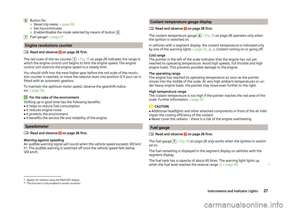
Button for:› Reset trip meter
» page 28
› Set hours/minutes
› Enable/disable the mode selected by means of button 5
Fuel gauge 1)
» page 27
Engine revolutions counter
Read and observe
on page 26 first.
The red scale of the rev counter
1
» Fig. 19 on page 26 indicates the range in
which the engine control unit begins to limit the engine speed. The engine
control unit restricts the engine speed to a steady limit.
You should shift into the next higher gear before the red scale of the revolu- tion counter is reached, or move the selector lever into position D if your car is
fitted with an automatic gearbox.
To maintain the optimum motor speed, observe the gearshift indica-
tor » page 28 .
For the sake of the environment
Shifting up in good time has the following benefits.■It helps to reduce fuel consumption.■
It reduces engine noise.
■
It protects the environment.
■
It benefits the service life and reliability of the engine.
Speedometer
Read and observe
on page 26 first.
Warning against speeding
An audible warning signal will sound when the vehicle speed exceeds 120 km/
h 2)
. The audible warning is switched off once the vehicle speed falls below
120 km/h.
67Coolant temperature gauge display
Read and observe
on page 26 first.
The coolant temperature gauge
4
» Fig. 19 on page 26 operates only when
the ignition is switched on.
In vehicles with a segment display, the coolant temperature is indicated only
by one of the warning lights » page 37,
Coolant coming on or going off.
Cold range
The pointer in the left of the scale indicates that the engine has not yet
reached its operating temperature. Avoid high speeds, full throttle and high engine loads. This prevents possible damage to the engine.
The operating range
The engine has reached its operating temperature as soon as the pointer
moves into the middle of the scale. At very high ambient temperatures or un-
der heavy engine loads, the pointer may move even further to the right.
High temperature range
The coolant temperature is too high if the pointer reaches the red area of the
scale. Further information » page 37.
CAUTION
■
Additional headlights and other attached components in front of the air inlet
impair the cooling efficiency of the coolant.■
Never cover the radiator - there is a risk of the engine overheating.
Fuel gauge
Read and observe
on page 26 first.
The fuel gauge
7
» Fig. 19 on page 26 only works when the ignition is switch-
ed on.
The fuel remaining is displayed in the segment display on vehicles with the
segment display.
The fuel tank has a capacity of about 45 litres. The warning light lights up
when the fuel level reaches the reserve range
» page 40 .
1)
Applies for vehicles using the MAXI DOT display.
2)
This function is only enabled in certain countries.
27Instruments and Indicator Lights
Page 39 of 197
The warning light comes on for a few seconds when the ignition is switch-
ed on 1)
.
Stop the vehicle, switch off the engine, and check the engine oil lev-
el » page 142 .
Even if the oil level is correct,
do not drive any further if the warning light is
flashing. Also do not leave the engine running at an idling speed.
Seek help from a specialist garage.
The warning light
lights up yellow (oil quantity too low)
The following message is shown in the MAXI DOT display.
Check oil level!
Stop the vehicle, switch off the engine, and check the engine oil lev-
el » page 142 .
An audible signal sounds as a warning signal.
The warning light will go out if the bonnet is left open for more than 30 sec-
onds. If no engine oil has been replenished, the warning light will come on
again after driving about 100 km.
The warning light flashes yellow (engine oil level sensor faulty)
The following message is shown in the MAXI DOT display.
Oil sensor workshop!
If the engine oil level sensor is faulty, the warning light flashes several
times and an audible signal sounds when the ignition is turned on.
Seek help from a specialist garage.WARNINGIf you have to stop for technical reasons, park the vehicle at a safe distance
from the traffic, switch off the engine and switch on the hazard warning
lights system » page 59.
CAUTION
The red oil pressure light is not an oil level indicator! One should therefore
check the oil level at regular intervals, preferably after every refuelling stop. Coolant
Read and observe
on page 35 first.
The indicator light
lights up until the engine reaches operating tempera-
ture 2)
. Avoid high speeds, full throttle and high engine loads.
If the warning light
lights up or flashes, either the coolant temperature is
too high or the coolant level is too low.
An audible signal sounds as a warning tone.
The following message is shown in the MAXI DOT display. ENGINE COOLANT PLEASE CHECK Log book!
Stop the vehicle, switch off the engine, check the level of the cool-
ant » page 144 , and refill the coolant if necessary » page 144.
If the coolant is within the specified range, the increased temperature may be
caused by an operating problem at the radiator fan. Check the fuse for the ra-
diator fan, replace if necessary » page 170, Fuses in the engine compartment .
Do not continue driving if the warning light
does not go off even though
the coolant level is correct and the fuse for the fan is in working order!
Seek help from a specialist garage.
WARNING■ If you have to stop for technical reasons, park the vehicle at a safe dis-
tance from the traffic, switch off the engine and activate the hazard warn-
ing light system » page 59.■
Carefully open the coolant expansion bottle. If the engine is hot, the cool-
ing system is pressurized - risk of scalding! It is therefore best to allow the
engine to cool down before removing the cap.
■
Do not touch the radiator fan. The radiator fan may switch itself on auto-
matically even if the ignition is off.
CAUTION
■ Additional headlights and other attached components in front of the air inlet
impair the cooling efficiency of the coolant.■
Never cover the radiator - there is a risk of the engine overheating.
1)
The warning light does not light up in vehicles fitted with the MAXI DOT display when the ignition is
switched on, but only if there is a fault or the engine oil level is too low.
2)
Not on vehicles with the MAXI DOT display.
37Instruments and Indicator Lights
Page 54 of 197
CAUTION■Keep the windows clean to ensure the correct functionality of the electric
windows.■
Should the windows freeze, first remove the ice » page 131, Windows and
exterior mirrors and only then operate the power windows. Otherwise, the
window seal and the power window mechanism could be damaged.
■
In the winter, ice on the window may cause greater resistance as the win-
dow is closed. The window will stop and open again by several centimetres.
■
Always make sure that the windows are closed when you leave the locked
vehicle.
For the sake of the environment
At high speeds, you should keep the windows closed to prevent unnecessarily high fuel consumption.
Note
■ After switching the ignition off, it is still possible to open or close the win-
dows for approx. 10 minutes. After the driver's or front passenger's door has
been opened, the windows can only be operated by using A
» Fig. 37 on
page 52 .
■
When driving always use the existing heating, air conditioning and ventila-
tion system for ventilating the interior of the vehicle. If the windows are
opened, dust as well as other dirt can get into the vehicle and in addition the
wind noise is more at certain speeds.
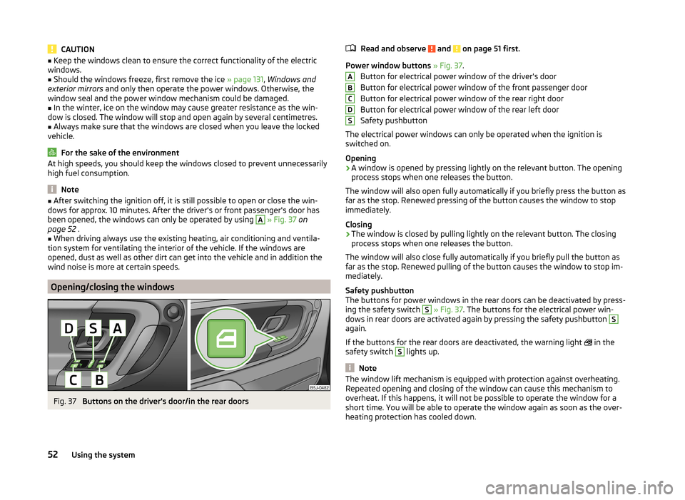
Opening/closing the windows
Fig. 37
Buttons on the driver's door/in the rear doors
Read and observe and on page 51 first.
Power window buttons » Fig. 37 .
Button for electrical power window of the driver's door
Button for electrical power window of the front passenger door
Button for electrical power window of the rear right door
Button for electrical power window of the rear left door
Safety pushbutton
The electrical power windows can only be operated when the ignition is
switched on.
Opening
›
A window is opened by pressing lightly on the relevant button. The opening
process stops when one releases the button.
The window will also open fully automatically if you briefly press the button as
far as the stop. Renewed pressing of the button causes the window to stop
immediately.
Closing
›
The window is closed by pulling lightly on the relevant button. The closing
process stops when one releases the button.
The window will also close fully automatically if you briefly pull the button as
far as the stop. Renewed pulling of the button causes the window to stop im-
mediately.
Safety pushbutton
The buttons for power windows in the rear doors can be deactivated by press-
ing the safety switch
S
» Fig. 37 . The buttons for the electrical power win-
dows in rear doors are activated again by pressing the safety pushbutton
S
again.
If the buttons for the rear doors are deactivated, the warning light in the
safety switch
S
lights up.
Note
The window lift mechanism is equipped with protection against overheating.
Repeated opening and closing of the window can cause this mechanism to
overheat. If this happens, it will not be possible to operate the window for a
short time. You will be able to operate the window again as soon as the over-
heating protection has cooled down.ABCDS52Using the system
Page 63 of 197
Luggage compartment light
The light comes on automatically when the boot lid is opened. If the tailgate remains open for more than 10 minutes, the luggage compartment light
switches off automatically.
Visibility
Introduction
This chapter contains information on the following subjects:
Rear window heating
61
Sun visors
61
Rear window heating
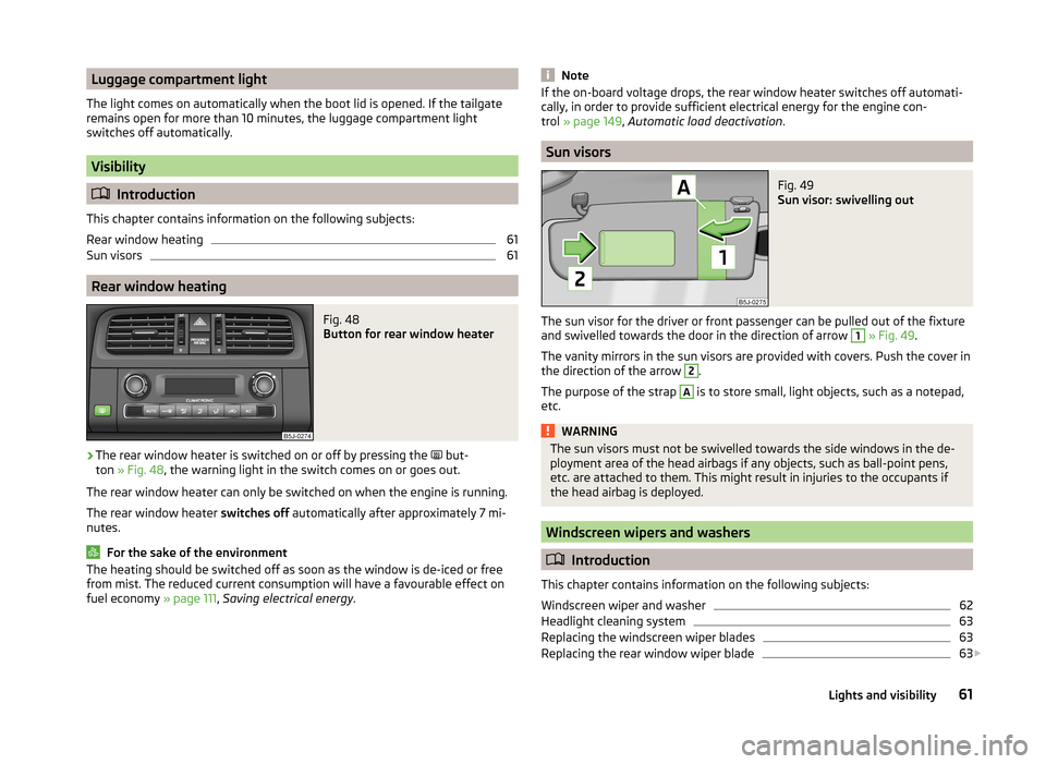
Fig. 48
Button for rear window heater
›
The rear window heater is switched on or off by pressing the but-
ton » Fig. 48 , the warning light in the switch comes on or goes out.
The rear window heater can only be switched on when the engine is running.
The rear window heater switches off automatically after approximately 7 mi-
nutes.
For the sake of the environment
The heating should be switched off as soon as the window is de-iced or free
from mist. The reduced current consumption will have a favourable effect on
fuel economy » page 111, Saving electrical energy .NoteIf the on-board voltage drops, the rear window heater switches off automati-
cally, in order to provide sufficient electrical energy for the engine con-
trol » page 149 , Automatic load deactivation .
Sun visors
Fig. 49
Sun visor: swivelling out
The sun visor for the driver or front passenger can be pulled out of the fixture
and swivelled towards the door in the direction of arrow
1
» Fig. 49 .
The vanity mirrors in the sun visors are provided with covers. Push the cover in
the direction of the arrow
2
.
The purpose of the strap
A
is to store small, light objects, such as a notepad,
etc.
WARNINGThe sun visors must not be swivelled towards the side windows in the de-
ployment area of the head airbags if any objects, such as ball-point pens,
etc. are attached to them. This might result in injuries to the occupants if
the head airbag is deployed.
Windscreen wipers and washers
Introduction
This chapter contains information on the following subjects:
Windscreen wiper and washer
62
Headlight cleaning system
63
Replacing the windscreen wiper blades
63
Replacing the rear window wiper blade
63
61Lights and visibility
Page 64 of 197
The windscreen wipers and the windscreen washer system only operate when
the ignition is switched on.
The rear window is wiped once automatically if the windscreen wipers are on
when reverse gear is selected.
Top up with windscreen wiper fluid » page 140.WARNING■
Properly maintained windscreen wiper blades are essential for clear visi-
bility and safe driving » page 63.■
Do not use the windscreen washer system at low temperatures, without
heating the windscreen beforehand. Otherwise the window cleaner could
freeze on the windscreen and restrict the view to the front.
■
Replace the windscreen wiper blades once or twice a year for safety rea-
sons. These can be purchased from a ŠKODA Partner.
CAUTION
■ In cold temperatures and during the winter, check before the journey or be-
fore switching on the ignition that the wiper blades are not frozen to the
windscreen. If the windscreen wipers are switched on when the blades are fro-
zen to the windscreen, this may damage both the blades and windscreen wip-
er motor!■
If the ignition is switched off while the windscreen wipers are switched on,
the windscreen wipers will continue wiping in the same mode after the igni-
tion is turned back on. The windscreen wipers could freeze up in cold tempera-
tures between the time the ignition was turned off and when it was turned
back on again.
■
Carefully detach frozen wiper blades from the front or rear window.
■
Remove snow and ice from the windscreen wipers before driving.
■
If the windscreen wipers are handled carelessly, there is a risk of damage to
the windscreen.
Note
■ The windscreen washer nozzles for the windscreen are heated when the en-
gine is running and the outside temperature is less than approx. +10 °C.■
The content of the windscreen washer fluid reservoir is 3.5 litres. On vehicles
fitted with the headlight cleaning system, the volume is around 5.4 litres.
■
The wiper blades should be cleaned on a regular basis with a windscreen
cleaner to avoid any smears. The wiper blades should be cleaned with a
sponge or cloth if they are heavily soiled by insect residues, for example.
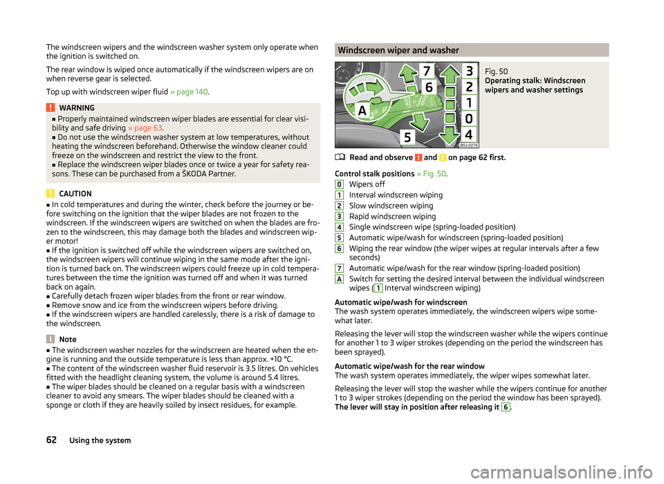
Windscreen wiper and washerFig. 50
Operating stalk: Windscreen
wipers and washer settings
Read and observe and on page 62 first.
Control stalk positions » Fig. 50 .
Wipers off
Interval windscreen wiping
Slow windscreen wiping
Rapid windscreen wiping
Single windscreen wipe (spring-loaded position)
Automatic wipe/wash for windscreen (spring-loaded position)
Wiping the rear window (the wiper wipes at regular intervals after a few seconds)
Automatic wipe/wash for the rear window (spring-loaded position)
Switch for setting the desired interval between the individual windscreen
wipes (
1
Interval windscreen wiping)
Automatic wipe/wash for windscreen
The wash system operates immediately, the windscreen wipers wipe some- what later.
Releasing the lever will stop the windscreen washer while the wipers continue
for another 1 to 3 wiper strokes (depending on the period the windscreen has
been sprayed).
Automatic wipe/wash for the rear window
The wash system operates immediately, the wiper wipes somewhat later.
Releasing the lever will stop the washer while the wipers continue for another
1 to 3 wiper strokes (depending on the period the window has been sprayed).
The lever will stay in position after releasing it
6
.
01234567A62Using the system
Page 67 of 197
Seats and storage
Front seats
Introduction
This chapter contains information on the following subjects:
Adjusting the front seats - Version 1
65
Adjusting the front seats - Variant 2
65
Front seat heating
66
The driver's seat should be adjusted in such a way that the pedals can be fully
pressed to the floor with slightly bent legs.
The seat backrest on the driver's seat should be adjusted in such a way that the upper point of the steering wheel can be easily reached with slightly bent
arms.
Correct adjustment of the seats is particularly important for the following rea-
sons.
› Reaching the controls safely and quickly.
› A relaxed and fatigue-free body position.
› Achieving the maximum protection offered by the seat belts and the airbag
system.
WARNING■ Only adjust the driver's seat when the vehicle is stationary – there is the
risk of an accident.■
Caution when adjusting the seat! You may suffer injuries or bruises as a
result of adjusting the seat without paying proper attention.
■
Never carry more people than the number of seats in the vehicle.
■
Do not transport any objects on the front passenger seat other than ob-
jects (e.g. child safety seat) intended for this purpose – there is the risk of
an accident.
Note
After a certain time, play can develop within the adjustment mechanism of the
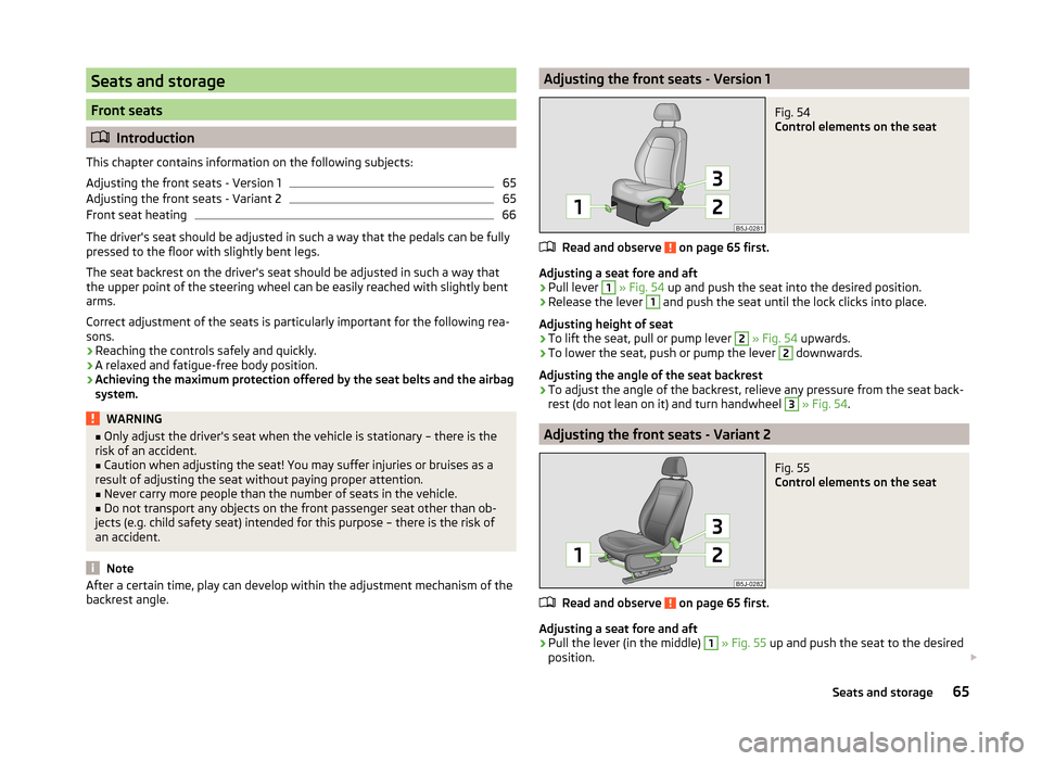
backrest angle.Adjusting the front seats - Version 1Fig. 54
Control elements on the seat
Read and observe on page 65 first.
Adjusting a seat fore and aft
›
Pull lever
1
» Fig. 54 up and push the seat into the desired position.
›
Release the lever
1
and push the seat until the lock clicks into place.
Adjusting height of seat
›
To lift the seat, pull or pump lever
2
» Fig. 54 upwards.
›
To lower the seat, push or pump the lever
2
downwards.
Adjusting the angle of the seat backrest
›
To adjust the angle of the backrest, relieve any pressure from the seat back-
rest (do not lean on it) and turn handwheel
3
» Fig. 54 .
Adjusting the front seats - Variant 2
Fig. 55
Control elements on the seat
Read and observe on page 65 first.
Adjusting a seat fore and aft
›
Pull the lever (in the middle)
1
» Fig. 55 up and push the seat to the desired
position.
65Seats and storage
Page 68 of 197
›Release the lever 1 and push the seat until the lock clicks into place.
Adjusting height of seat›
To lift the seat, pull or pump lever
2
» Fig. 55 upwards.
›
To lower the seat, push or pump the lever
2
downwards.
Adjusting the angle of the seat backrest
›
Relieve the load on the seat backrest (do not lean on it), pull the lever
3
» Fig. 55 towards the rear and set the desired angle of the seat backrest
with the back.
›
After releasing the lever
3
, the seat backrest will remain in the set position.
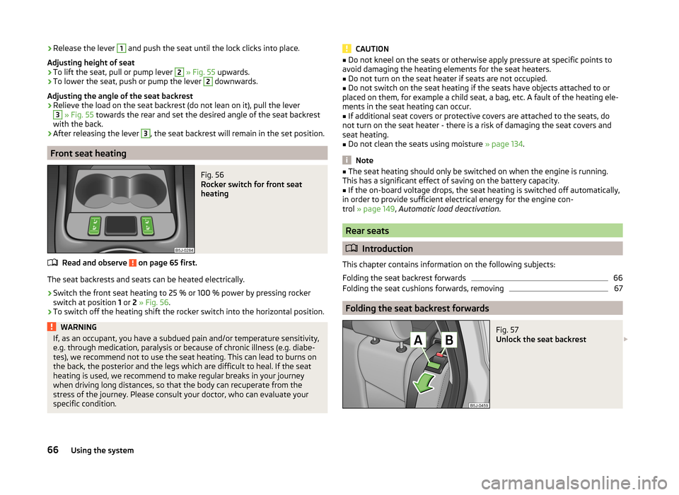
Front seat heating
Fig. 56
Rocker switch for front seat
heating
Read and observe on page 65 first.
The seat backrests and seats can be heated electrically.
›
Switch the front seat heating to 25 % or 100 % power by pressing rocker
switch at position 1 or 2 » Fig. 56 .
›
To switch off the heating shift the rocker switch into the horizontal position.
WARNINGIf, as an occupant, you have a subdued pain and/or temperature sensitivity,
e.g. through medication, paralysis or because of chronic illness (e.g. diabe-
tes), we recommend not to use the seat heating. This can lead to burns on
the back, the posterior and the legs which are difficult to heal. If the seat
heating is used, we recommend to make regular breaks in your journey
when driving long distances, so that the body can recuperate from the
stress of the journey. Please consult your doctor, who can evaluate your
specific condition.CAUTION■ Do not kneel on the seats or otherwise apply pressure at specific points to
avoid damaging the heating elements for the seat heaters.■
Do not turn on the seat heater if seats are not occupied.
■
Do not switch on the seat heating if the seats have objects attached to or
placed on them, for example a child seat, a bag, etc. A fault of the heating ele-
ments in the seat heating can occur.
■
If additional seat covers or protective covers are attached to the seats, do
not turn on the seat heater - there is a risk of damaging the seat covers and
seat heating.
■
Do not clean the seats using moisture » page 134.
Note
■
The seat heating should only be switched on when the engine is running.
This has a significant effect of saving on the battery capacity.■
If the on-board voltage drops, the seat heating is switched off automatically,
in order to provide sufficient electrical energy for the engine con-
trol » page 149 , Automatic load deactivation .
Rear seats
Introduction
This chapter contains information on the following subjects:
Folding the seat backrest forwards
66
Folding the seat cushions forwards, removing
67
Folding the seat backrest forwards
Fig. 57
Unlock the seat backrest
66Using the system
Page 71 of 197
Example: In the event of a frontal collision at a speed of 50 km/h, an object
weighing 4.5 kg produces energy corresponding to 20 times its own weight.
This means that it results in a weight of approx. 90 kg “ ”.WARNING■ Store the objects in the boot and attach them to the lashing eyes.■Loose objects can be thrown forward during a sudden manoeuvre or in
case of an accident and can injure the occupants or other road users.■
Loose objects could hit a deployed airbag and injure occupants – there is
a risk of death.
■
Please note that the handling properties of the vehicle may be affected
when transporting heavy objects as the centre of gravity can be shifted –
there is a risk of an accident. The speed and style of driving must be adjus-
ted accordingly.
■
If the items of luggage or objects are attached to the lashing eyes with
unsuitable or damaged lashing straps, injuries can occur in the event of
braking manoeuvres or accidents. To prevent items of luggage from being
thrown forward, always use suitable lashing straps which must be firmly at-
tached to the lashing eyes.
■
Items carried in the luggage compartment must be stowed in such a way
that no objects are able to slip forward under sudden driving manoeuvres
or braking – there is a risk of injury.
■
When transporting fastened objects which are sharp and dangerous in
the boot that has been enlarged by folding the rear seats forward, ensure
the safety of the passengers transported on the other rear seats » page 9,
Correct seated position of the rear seat passengers .
■
If the rear seat next to the folded forward seat is occupied, ensure maxi-
mum safety, e.g. by placing the goods to be transported in such a way that
the seat is prevented from folding back in case of a rear collision.
■
Never drive with the tailgate fully opened or slightly ajar otherwise ex-
haust gases may get into the interior of the vehicle – risk of poisoning.
■
Under no circumstances, should the permissible axle loads and permissi-
ble gross weight of the vehicle be exceeded – there is the risk of an acci-
dent.
■
Never transport people in the boot!
CAUTION
Please ensure that the heating elements for the rear window heater are not
damaged as a result of abrasive objects.NoteTyre pressure must be adjusted to the load » page 151, Tyre service life .
Class N1 vehicles
Read and observe
and on page 69 first.
On class N1 vehicles, which are not fitted with a protective grille, a lashing set
which complies with the standard EN 12195 (1 - 4) must be used for fastening
the load.
The proper functioning of the electrical system is essential for the safe opera-
tion of the vehicle. It is important to ensure that it is not damaged during mod-
ifications or when loading or unloading the luggage compartment.
Fastening elements
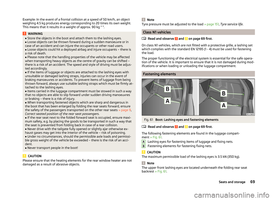
Fig. 61
Boot: Lashing eyes and fastening elements
Read and observe
and on page 69 first.
The following fastening elements are found in the luggage compart-
ment » Fig. 61 .
Lashing eyes for fastening items of luggage and fixing nets.
Fastening elements for fastening fixing nets.
CAUTION
The maximum permissible load of the lashing eyes is 3.5 kN (350 kg).
Note
The upper front lashing eyes are located underneath the folding rear seat
backrest » Fig. 61.AB69Seats and storage