instrument cluster SKODA FABIA 2014 2.G / 5J Owner's Manual
[x] Cancel search | Manufacturer: SKODA, Model Year: 2014, Model line: FABIA, Model: SKODA FABIA 2014 2.G / 5JPages: 197, PDF Size: 13.56 MB
Page 5 of 197
Table of Contents
Abbreviations
Safety
Passive Safety
6
General information
6
Correct and safe seated position
7
Seat belts
10
Wearing seat belts
10
Inertia reel and belt pretensioners
13
Airbag system
14
Description of the airbag system
14
Airbag overview
15
Deactivating airbags
17
Transporting children safely
19
Child seat
19
Fastening systems
22
Using the system
Cockpit
25
Overview
24
Instruments and Indicator Lights
26
Instrument cluster
26
Multifunction display (MFD)
29
Service Interval Display
32
MAXI DOT display
33
Warning lights
35
Unlocking and locking
42
Unlocking and locking
42
Central locking system
45
Remote control
48
Anti-theft alarm system
49
Tailgate
50Electrical power windows51Electric sliding/tilting roof53
Lights and visibility
55
Lights
55
Interior lights
59
Visibility
61
Windscreen wipers and washers
61
Rear window
63
Seats and storage
65
Front seats
65
Rear seats
66
Head restraints
67
Boot
68
Variable loading floor in the luggage
compartment (Fabia Estate)
72
Net partition (Fabia Estate)
73
Bicycle carrier in the luggage compartment
75
Roof rack system
76
Useful equipment
77
Storage compartments
80
Heating and air conditioning
84
Heating, ventilation, cooling
84
Heating
86
Air conditioning system (manual air
conditioning system)
87
Climatronic (automatic air conditioning
system)
90
Communication and multimedia
92
Universal telephone preinstallation GSM II
92
Voice control
97
Multimedia
98
Driving
Starting-off and Driving
101
Starting and stopping the engine
101
Brakes
102Manual gear shifting and pedals104Automatic transmission105
Running in
108
Economical driving and respect the
environment
109
Avoiding damage to your vehicle
112
Driving abroad
113
Assist systems
114
Brake assist systems
114
Parking aid
116
Cruise control system
117
START-STOP
118
Towing a trailer
120
Towing device
120
Trailer
124
General Maintenance
Car care
126
Services, modifications and technical
alterations
126
Washing the car
128
Vehicle exterior care
129
Care of the interior
132
Inspecting and replenishing
135
Fuel
135
Engine compartment
138
Engine oil
141
Coolant
143
Brake fluid
145
Vehicle battery
145
Wheels
149
Tyres and rims
149
Winter use
1563Table of Contents
Page 16 of 197

Airbag system
Description of the airbag system
Introduction
This chapter contains information on the following subjects:
System description
14
Airbag deployment
14WARNING■ An airbag can only offer you optimal protection in combination with a fas-
tened seat belt.■
The airbag is not a substitute for the seat belt, but instead forms part of
the complete passive vehicle safety concept.
■
To ensure passengers are protected with the greatest possible effect
when the airbag is deployed, the front seats must be correctly adjusted to
match the body size » page 7, Correct and safe seated position .
■
If you do not fasten the seat belts when driving, lean too far forward or
adopt an incorrect seated position, you are exposing yourself to increased
risk of injury in the event of an accident.
WARNINGInformation on the use of the airbag system■If there is a fault, the airbag system must be checked by a specialist ga-
rage immediately. Otherwise, there is a risk of the airbag not being activa-
ted in the event of an accident.■
No modifications of any kind must be made to parts of the airbag system.
■
Any work on the airbag system including the installation and removal of
system components due to other repair work (e.g. removal of the steering
wheel) must only be carried out by a specialist garage.
■
Never make any changes to the front bumper or bodywork.
■
It is prohibited to tamper with individual parts of the airbag system as this
might result in the airbag being deployed.
■
The protective function of the airbag system is sufficient for only one ac-
cident. The airbag system must then be replaced if the airbag has been de-
ployed.
System description
Read and observe
on page 14 first.
The functional status of the airbag system is indicated by the
indicator light
in the instrument cluster » page 40.
When the airbags are deployed they fill with gas and inflate.
A grey white or red, non-harmful gas is released when the airbag is inflated.
This is perfectly normal and is not an indication of a fire in the vehicle.
The airbag system consists – depending on the vehicle equipment – of the
following modules.
› Electronic control unit.
› Front airbag for the driver and the front passenger
» page 15.
› Side airbags
» page 16.
› Head airbags
» page 17.
› Airbag indicator light in the instrument cluster
» page 40.
› Key switch for the front passenger airbag
» page 18.
› Warning light for front passenger airbag deactivation in dash panel cen-
tre » page 18 .
Note
■
The airbag system needs no maintenance during its working life.■If you sell your vehicle, provide the complete vehicle documentation to the
new owner. Please note that the information relating to the possibility of de-
activating the front passenger airbag must be included!■
When disposing of vehicle or parts of the airbag system, it is important to
comply with the national legal requirements.
Airbag deployment
Read and observe
on page 14 first.
The airbags inflate in fractions of a second and at a high speed in order to be
able to offer that additional protection in the event of an accident.
The airbag system is only functional when the ignition is switched on.
In certain accident situations, the several airbags may be deployed simultane-
ously.
The airbags are not deployed in the case of minor frontal and side collisions,
rear-end collisions, tilting of the vehicle and vehicle rollover.
14Safety
Page 27 of 197
Using the system
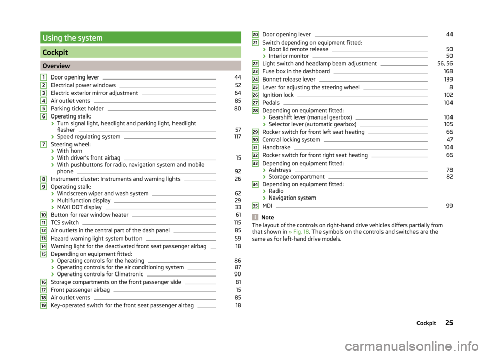
Cockpit
OverviewDoor opening lever
44
Electrical power windows
52
Electric exterior mirror adjustment
64
Air outlet vents
85
Parking ticket holder
80
Operating stalk:
› Turn signal light, headlight and parking light, headlight
flasher
57
› Speed regulating system
117
Steering wheel:
› With horn
› With driver’s front airbag
15
›With pushbuttons for radio, navigation system and mobile
phone
92
Instrument cluster: Instruments and warning lights
26
Operating stalk:
› Windscreen wiper and wash system
62
›Multifunction display
29
›MAXI DOT display
33
Button for rear window heater
61
TCS switch
115
Air outlets in the central part of the dash panel
85
Hazard warning light system button
59
Warning light for the deactivated front seat passenger airbag
18
Depending on equipment fitted:
› Operating controls for the heating
86
›Operating controls for the air conditioning system
87
›Operating controls for Climatronic
90
Storage compartments on the front passenger side
81
Front passenger airbag
15
Air outlet vents
85
Key-operated switch for the front seat passenger airbag
1812345678910111213141516171819Door opening lever44
Switch depending on equipment fitted:
› Boot lid remote release
50
›Interior monitor
50
Light switch and headlamp beam adjustment
56, 56
Fuse box in the dashboard
168
Bonnet release lever
139
Lever for adjusting the steering wheel
8
Ignition lock
102
Pedals
104
Depending on equipment fitted:
› Gearshift lever (manual gearbox)
104
›Selector lever (automatic gearbox)
105
Rocker switch for front left seat heating
66
Central locking system
47
Handbrake
104
Rocker switch for front right seat heating
66
Depending on equipment fitted:
› Ashtrays
78
›Storage compartment
82
Depending on equipment fitted:
› Radio
› Navigation system
MDI
99
Note
The layout of the controls on right-hand drive vehicles differs partially from
that shown in » Fig. 18. The symbols on the controls and switches are the
same as for left-hand drive models.2021222324252627282930313233343525Cockpit
Page 28 of 197
Instruments and Indicator Lights
Instrument cluster
Introduction
This chapter contains information on the following subjects:
Overview
26
Engine revolutions counter
27
Speedometer
27
Coolant temperature gauge display
27
Fuel gauge
27
Counter for distance driven
28
Digital clock
28
Display of the second speed
28
Recommended gear
28
Fault display
The Error message will appear in the display if there is a fault in the instru-
ment cluster. Ensure that the fault is rectified as soon as possible by a special-
ist workshop.
WARNING■ Concentrate fully at all times on your driving! As the driver you are fully
responsible for road safety.■
Never operate the controls in the instrument cluster while driving, only
when the vehicle is stationary!
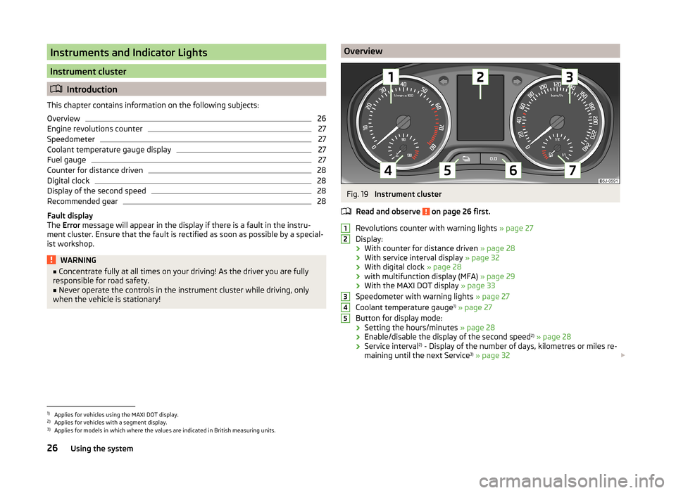
OverviewFig. 19
Instrument cluster
Read and observe
on page 26 first.
Revolutions counter with warning lights » page 27
Display:
› With counter for distance driven
» page 28
› With service interval display
» page 32
› With digital clock
» page 28
› with multifunction display (MFA)
» page 29
› With the MAXI DOT display
» page 33
Speedometer with warning lights » page 27
Coolant temperature gauge 1)
» page 27
Button for display mode:
› Setting the hours/minutes
» page 28
› Enable/disable the display of the second speed 2)
» page 28
› Service interval 2)
- Display of the number of days, kilometres or miles re-
maining until the next Service 3)
» page 32
123451)
Applies for vehicles using the MAXI DOT display.
2)
Applies for vehicles with a segment display.
3)
Applies for models in which where the values are indicated in British measuring units.
26Using the system
Page 30 of 197
CAUTIONNever drive until the fuel tank is completely empty! The irregular supply of fuel
can cause misfiring. This can result in considerable damage to parts of the en-
gine and the exhaust system.
Counter for distance driven
Read and observe
on page 26 first.
The distance which you have driven with your vehicle is shown in km. In some
countries the measuring unit “mile” is used.
Daily trip counter (trip)
The trip counter indicates the distance you have driven since it was last reset -
in steps of 100 metres or 1/10 of a mile.
Reset trip meter
The meter can be reset by pressing and holding button
6
» Fig. 19 on page 26 .
Odometer
The odometer indicates the total distance in kilometres or miles which the ve-
hicle has been driven.
Note
If the second speed display is enabled on vehicles with a segment display, this
speed will be shown instead of the odometer.
Digital clock
Read and observe
on page 26 first.
The clock is set with buttons
5
and
6
» Fig. 19 on page 26 .
Select the display that you wish to change with the button
5
and carry out
the change with the button
6
.
In vehicles equipped with the MAXI DOT display, it is also possible to set the
clock in the Time menu » page 34.
Display of the second speed
Read and observe
on page 26 first.
The display can show the current speed in mph 1)
.
This feature is provided for driving in countries with different units for speed.
MAXI DOT display
The display of the second speed can be set in the Settings menu
item » page 34 , Settings .
Segment display
›
Press the
5
» Fig. 19 on page 26 key repeatedly, until the odometer display
flashes » page 28 .
›
Press the
6
key while the display is flashing.
The second speed is displayed instead of the odometer.
Display of the second speed can be disabled in the same way.
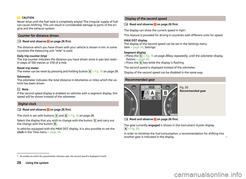
Recommended gear
Fig. 20
Recommended gear
Read and observe on page 26 first.
The gear currently engaged is shown in the instrument cluster display
A
» Fig. 20 .
In order to minimise the fuel consumption, a recommendation for shifting into
another gear is indicated in the display.
1)
On models on which the speedometer indicates mph, the second speed is displayed in km/h.
28Using the system
Page 34 of 197
The speed limit set mode is stored even after the ignition is switched off and
on.
Service Interval Display
Introduction
This chapter contains information on the following subjects:
Prompt in the segment display
32
Display in the MAXI DOT display
33
A message concerning the kilometres and days remaining until the next
service is due is shown for about 10 seconds after the ignition is switched on
until the end of the service interval is reached.
The kilometre indicator or the days indicator reduces in steps of 100 km or
days until the service due date is reached.
Resetting the oil change service indicator in a specialist dealer's
For vehicles with variable service intervals, after resetting the screen displays,
the values of a new service interval is displayed, which are based on the previ-
ous operating conditions of the vehicle.
These values are then further continuously matched according to the actual
operating conditions of the vehicle.
Note
■ Information is retained in the Service Interval Display even after the vehicle
battery is disconnected.■
If the instrument cluster is exchanged after a repair, the correct values must
be entered in the counter for the Service Interval Display. This work will be
done by a specialist garage.
■
For more information on the service intervals, see the » Serviceplan , chap-
ter service schedules .
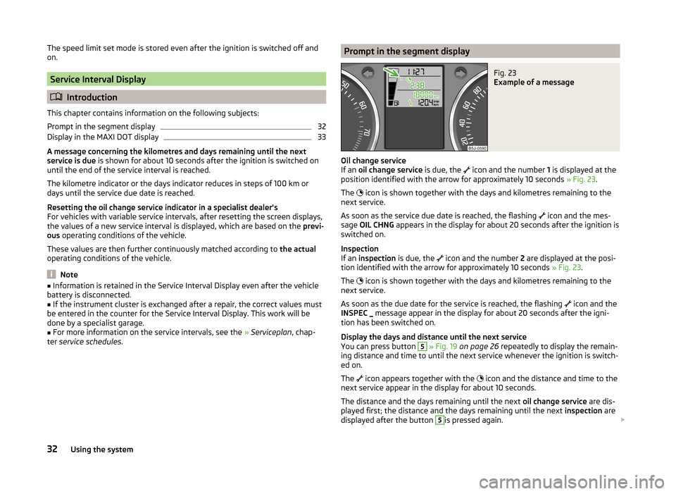
Prompt in the segment displayFig. 23
Example of a message
Oil change service
If an oil change service is due, the
icon and the number
1 is displayed at the
position identified with the arrow for approximately 10 seconds » Fig. 23.
The icon is shown together with the days and kilometres remaining to the
next service.
As soon as the service due date is reached, the flashing icon and the mes-
sage OIL CHNG appears in the display for about 20 seconds after the ignition is
switched on.
Inspection
If an inspection is due, the
icon and the number
2 are displayed at the posi-
tion identified with the arrow for approximately 10 seconds » Fig. 23.
The icon is shown together with the days and kilometres remaining to the
next service.
As soon as the due date for the service is reached, the flashing icon and the
INSPEC _ message appear in the display for about 20 seconds after the igni-
tion has been switched on.
Display the days and distance until the next service
You can press button
5
» Fig. 19 on page 26 repeatedly to display the remain-
ing distance and time to until the next service whenever the ignition is switch-
ed on.
The icon appears together with the
icon and the distance and time to the
next service appear in the display for about 10 seconds.
The distance and the days remaining until the next oil change service are dis-
played first; the distance and the days remaining until the next inspection are
displayed after the button
5
is pressed again.
32Using the system
Page 36 of 197
SettingsRead and observe
on page 33 first.
You can change certain settings yourself through the MAXI DOT display. The
current menu item is shown in the top of the display under a line.
You can select the following menu options:
Language
You can set the language for the warning and information texts here.
MFD data
Activate or deactivate certain displays of the multifunction display here.
Time
The time, time format (12 or 24 hour indicator) and the changeover between
summer/winter time can be set here.
Winter tyres
Here, you can set the speed at which an audible signal should sound. This
function is, for example, used for winter tyres where the maximum permissible
speed is lower than the maximum speed of the vehicle.
The following is shown on the information display if this speed is exceeded: Winter tyres max. speed ... km/h.
Units of measurement
The units for the temperature, consumption and distance driven can be set
here.
Alt. speed dis.
Display of the second speed in mph 1)
can be activated here.
Service
The days and kilometres remaining until the next service can be displayed
here.
Factory setting
The display can be restored to its factory settings here.
Door, boot lid and bonnet warning
Read and observe
on page 33 first.
If at least one door is open, or the boot or bonnet is open, the MAXI DOT dis-
play shows the vehicle with the corresponding door or boot/bonnet open.
An audible signal also sounds if the vehicle is travelling at more than 6 km/h.
Auto Check Control
Read and observe
on page 33 first.
Vehicle condition
Certain functions and conditions of individual vehicle systems are checked
continuously when the ignition is switched on and also while driving.
Some error messages and other information are displayed in the MAXI DOT
display. The messages are displayed simultaneously with the icons in the MAXI
DOT display or with the warning lights in the instrument cluster » page 35.
The Vehicle status menu item is shown in the main menu of the MAXI DOT
display whenever at least one fault message is present. The first of the fault
messages is displayed after this menu item is selected. Several error messages
are shown on the display under the message e.g. 1/3. This indicates that the
first of a total of three error messages is being displayed.
As long as the operational faults are not rectified, the symbols are always indi-
cated again. After they are displayed for the first time, the symbols continue to
be indicated without any extra messages for the driver.
Warning symbols
Engine oil pressure too low» page 36Clutches of the automatic DSG gearbox
are too hot» page 34Check engine oil level,
engine oil sensor defective» page 36
Clutches of the automatic DSG gearbox are too hot
If the symbol appears in the MAXI DOT display, this indicates that the tem-
perature of the automatic DSG gearbox clutches is too high.
1)
On models on which the speedometer indicates mph, the second speed is displayed in km/h.
34Using the system
Page 40 of 197
Power steeringRead and observe
on page 35 first.
The warning light
comes on for a few seconds when the ignition is switched
on.
If the warning light after switching on the ignition or when driving lights up
continuously, a fault exists in the electrohydraulic power steering. The power
steering operates with reduced steering assist or does not function at all.
Seek help from a specialist garage.
Note
■ If the yellow warning light goes out after the engine is restarted and a
short drive, it is not necessary to visit a specialist garage.■
If the vehicle battery has been disconnected and reconnected, the yellow
warning light
comes on after switching on the ignition. The warning light
should go out after driving a short distance.
■
There is no power-assisted steering support when the vehicle is being towed
without the engine running or when the power-assisted steering is defect.
The vehicle is fully steerable however. There is however increased force re-
quired to turn the steering wheel.
Electronic Stability Control (ESC)
Read and observe
on page 35 first.
The warning light flashes to show that the ESC is currently operating.
If the warning light comes on immediately after you start the engine, the
ESC might be switched off due to technical reasons. Switch the ignition off and
on again. The ESC is fully functional again if the warning light does not light
up after you switch the engine back on.
There is a fault in the ESC system if the warning light lights up.
The following message is shown in the MAXI DOT display. Error: Electronic Stability Control (ESC)
Seek help from a specialist garage.
The ESC system cannot be turned off, the
» page 115 button only switches
the TCS off, the warning light in the instrument cluster lights up.
As the ESC operates in conjunction with the ABS, the ESP indicator light will
also come on if the ABS system fails.
Further information » page 114, Stabilisation control (ESC) .
Note
The warning light comes on after the ignition is switched on if the vehicle's
battery has been disconnected and reconnected. The warning light should go
out after the vehicle has driven a short distance.
Traction Control System (ASR)
Read and observe
on page 35 first.
The warning light flashes to show that the ASR is currently operating.
If the warning light comes on immediately after starting the engine, the ASR
can be switched off for technical reasons. Switch the ignition off and on again.
The TCS is fully functional again if the warning light does not light up after
you switch the engine back on.
If the warning light lights up, there is a fault in the ASR.
The following message is shown in the MAXI DOT display. Error: Traction control (ASR)
Seek help from a specialist garage.
The fact that the TCS system operates together with the ABS means that the TCS warning light will also come on if the ABS system is not operating proper-
ly.
Further information » page 115, Traction Control System (ASR) .
Note
The warning light comes on after the ignition is switched on if the vehicle's
battery has been disconnected and reconnected. The warning light should go
out after the vehicle has driven a short distance.
Antilock brake system (ABS)
Read and observe
on page 35 first.
If the warning light
lights up, there is a fault in the ABS.
38Using the system
Page 48 of 197
Warning light in the driver's door
After locking the vehicle, the warning light flashes for around 2 seconds in
quick succession, afterwards it begins to flash evenly at longer intervals.
If the vehicle is locked and the safe securing system » page 46 is not operat-
ing, the warning light in the driver door flashes for about 2 seconds fast, goes
out and starts to flash evenly at longer intervals after about 30 seconds.
If the indicator light first flashes fast for about 2 seconds, then lights up for
about 30 seconds continuously and then flashes slowly, there is a fault in the
central locking system or in the interior monitor and in the towing protec-
tion » page 50 . Seek help from a specialist garage.
Convenience operation of windows
The windows can be opened and closed when unlocking and locking the vehi-
cle » page 53 .
CAUTION
If the safe securing system is activated » page 46, the door opening lever and
the central locking buttons do not operate.
Note
■ In the event of an accident in which the airbags are deployed, the locked
doors are automatically unlocked in order to enable rescuers to gain access to
the vehicle.■
Upon failure of the central locking system the key can only be used for lock-
ing and unlocking the driver's door. The other doors and the boot lid can be
manually locked or unlocked. ■ Emergency locking of the door » page 45.
■ Emergency unlocking of the boot lid » page 51.
Individual settings
Read and observe
on page 46 first.
Opening a single door
This selection function makes it possible to only unlock the driver's door. The other doors remain locked and are only unlocked when the command is repea-
ted.
Automatic locking and unlocking
All the doors and the boot lid are locked automatically once the car reaches a
speed of about 15 km/h.
If the ignition key is withdrawn, the car is then automatically unlocked again.
In addition, it is possible for the driver or front passenger to unlock the car by
pressing the central locking button
» page 47 .
The doors can be unlocked and opened from the inside by a single pull on the
opening lever of the respective door.
Note
Individual settings can be applied in a specialist workshop.
Safe securing
Read and observe
on page 46 first.
The central locking system is equipped with a safe securing system. The door
locks are blocked automatically if the vehicle is locked from the outside. It is
then not possible to open the doors with the door handle, either from the in-
side or from the outside.
You will be informed that the safe securing system is activated after the vehi-
cle is locked by the CHECK DEADLOCK message on the instrument cluster dis-
play. On vehicles equipped with the MAXI DOT display, the display shows
Check deadlock. Log book!
Switching off
Opening can take place in one of the following ways.
›
By locking twice within 2 seconds.
›
By disabling the interior monitoring » page 50, Interior monitor and towing
protection .
If the vehicle is locked and the safe securing system is switched off, the door can be opened separately from the inside by a single pull on the opening lever.
Switching on
The safelock switches on automatically the next time the vehicle is locked and
unlocked.
Switch-on display
The warning light flashes for around 2 seconds in quick succession, afterwards
it begins to flash evenly at longer intervals.
Switch-off display
The indicator light in the driver door flashes for about 2 seconds fast, goes out
and starts to flash regularly at longer intervals after about 30 seconds.
46Using the system
Page 59 of 197
Activating on vehicles with the START-STOP system›Switch off the ignition.›
At the same time, pull the turn signal light stalk » Fig. 42 on page 57 to-
wards the steering wheel, push it upwards, and hold it in this position.
›
Switch on the ignition - wait until the right-turn signal light flashes 4x.
›
Switch off the ignition - an audible signal sounds which confirms the activa-
tion of the daylight driving lights.
›
Release the turn signal stalk.
On vehicles with separate lights for daylight driving lights in the fog lights or in
the front bumper, the parking lights and the licence plate light do not come on
when activating the function daylight driving lights (neither front nor rear).
If the vehicle is not equipped with separate lights for daylight driving lights,
the combination of the low beam, the parking lights (front and rear) including
the licence plate light is used as daylight driving lights.
Note
In vehicles with separate lights for daylight driving lights (in the bumper below
the main headlights) these lights also serve as side lights.
Turn signal and main beam lights
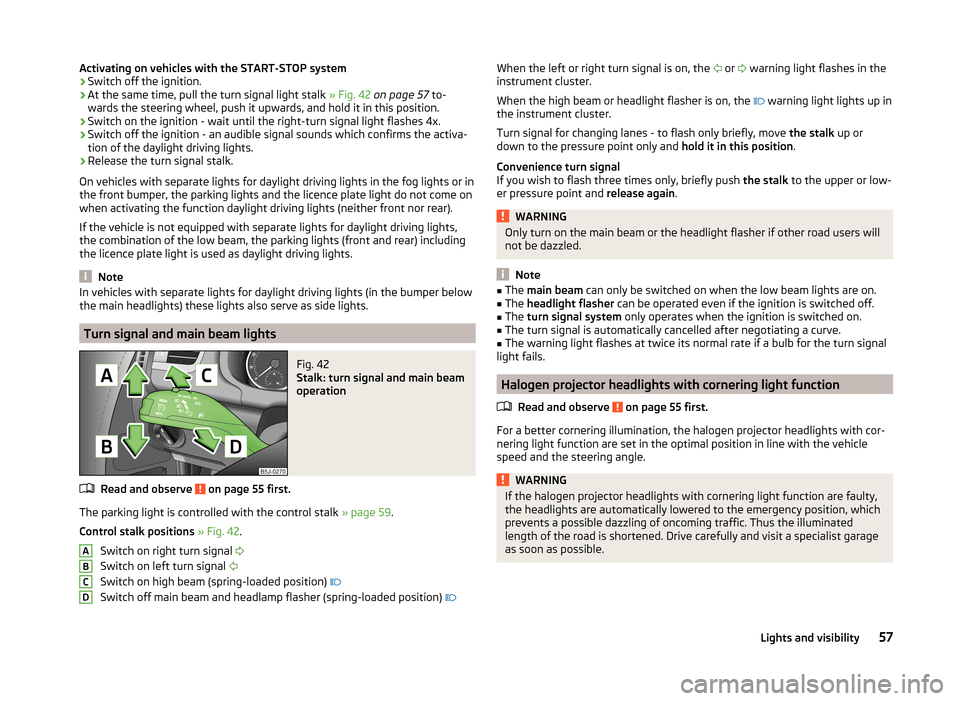
Fig. 42
Stalk: turn signal and main beam
operation
Read and observe on page 55 first.
The parking light is controlled with the control stalk » page 59.
Control stalk positions » Fig. 42 .
Switch on right turn signal
Switch on left turn signal
Switch on high beam (spring-loaded position)
Switch off main beam and headlamp flasher (spring-loaded position)
ABCDWhen the left or right turn signal is on, the
or warning light flashes in the
instrument cluster.
When the high beam or headlight flasher is on, the
warning light lights up in
the instrument cluster.
Turn signal for changing lanes - to flash only briefly, move the stalk up or
down to the pressure point only and hold it in this position.
Convenience turn signal
If you wish to flash three times only, briefly push the stalk to the upper or low-
er pressure point and release again.WARNINGOnly turn on the main beam or the headlight flasher if other road users will
not be dazzled.
Note
■ The main beam can only be switched on when the low beam lights are on.■The headlight flasher can be operated even if the ignition is switched off.■
The turn signal system only operates when the ignition is switched on.
■
The turn signal is automatically cancelled after negotiating a curve.
■
The warning light flashes at twice its normal rate if a bulb for the turn signal
light fails.
Halogen projector headlights with cornering light function
Read and observe
on page 55 first.
For a better cornering illumination, the halogen projector headlights with cor-
nering light function are set in the optimal position in line with the vehicle
speed and the steering angle.
WARNINGIf the halogen projector headlights with cornering light function are faulty,
the headlights are automatically lowered to the emergency position, which
prevents a possible dazzling of oncoming traffic. Thus the illuminated
length of the road is shortened. Drive carefully and visit a specialist garage
as soon as possible.57Lights and visibility