power steering SKODA FABIA 2014 2.G / 5J Owner's Manual
[x] Cancel search | Manufacturer: SKODA, Model Year: 2014, Model line: FABIA, Model: SKODA FABIA 2014 2.G / 5JPages: 197, PDF Size: 13.56 MB
Page 27 of 197
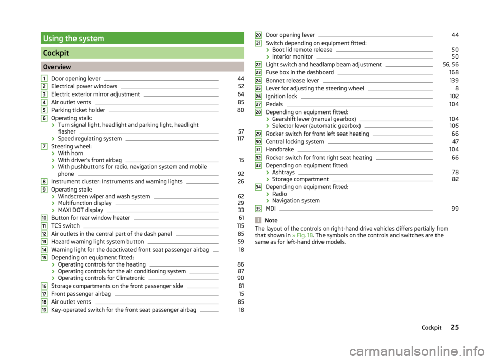
Using the system
Cockpit
OverviewDoor opening lever
44
Electrical power windows
52
Electric exterior mirror adjustment
64
Air outlet vents
85
Parking ticket holder
80
Operating stalk:
› Turn signal light, headlight and parking light, headlight
flasher
57
› Speed regulating system
117
Steering wheel:
› With horn
› With driver’s front airbag
15
›With pushbuttons for radio, navigation system and mobile
phone
92
Instrument cluster: Instruments and warning lights
26
Operating stalk:
› Windscreen wiper and wash system
62
›Multifunction display
29
›MAXI DOT display
33
Button for rear window heater
61
TCS switch
115
Air outlets in the central part of the dash panel
85
Hazard warning light system button
59
Warning light for the deactivated front seat passenger airbag
18
Depending on equipment fitted:
› Operating controls for the heating
86
›Operating controls for the air conditioning system
87
›Operating controls for Climatronic
90
Storage compartments on the front passenger side
81
Front passenger airbag
15
Air outlet vents
85
Key-operated switch for the front seat passenger airbag
1812345678910111213141516171819Door opening lever44
Switch depending on equipment fitted:
› Boot lid remote release
50
›Interior monitor
50
Light switch and headlamp beam adjustment
56, 56
Fuse box in the dashboard
168
Bonnet release lever
139
Lever for adjusting the steering wheel
8
Ignition lock
102
Pedals
104
Depending on equipment fitted:
› Gearshift lever (manual gearbox)
104
›Selector lever (automatic gearbox)
105
Rocker switch for front left seat heating
66
Central locking system
47
Handbrake
104
Rocker switch for front right seat heating
66
Depending on equipment fitted:
› Ashtrays
78
›Storage compartment
82
Depending on equipment fitted:
› Radio
› Navigation system
MDI
99
Note
The layout of the controls on right-hand drive vehicles differs partially from
that shown in » Fig. 18. The symbols on the controls and switches are the
same as for left-hand drive models.2021222324252627282930313233343525Cockpit
Page 37 of 197
The following message is shown in the MAXI DOT display.Gearbox overheated. Stop. Log book!
Stop the vehicle, switch off the engine, and wait until the
icon goes out –
there is a risk of gearbox damage. You can continue your journey as soon as
the icon disappears.WARNINGIf you have to stop for technical reasons, park the vehicle at a safe distance
from the traffic, switch off the engine and activate the hazard warning light
system » page 59 .
Note
■
Warning messages shown in the MAXI DOT display must be confirmed with
button B » Fig. 24 on page 33 to call up the main menu.■
As long as the operational faults are not rectified, the symbols are always in-
dicated again. After they are displayed for the first time, the symbols continue
to be indicated without any extra messages for the driver.
Warning lights
Introduction
This chapter contains information on the following subjects:
Handbrake
35
Brake system
36
Seat belt warning light
36
Generator
36
OPen door
36
Engine oil
36
Coolant
37
Power steering
38
Electronic Stability Control (ESC)
38
Traction Control System (ASR)
38
Antilock brake system (ABS)
38
The rear fog light
39
Bulb failure
39
Exhaust inspection system
39
Glow plug system (diesel engine)
39 EPC fault light (petrol engine)39 Diesel particulate filter (diesel engine)39
Fuel reserve
40
Airbag system
40
Tyre pressure
41
Windscreen washer fluid level
41
Traction control (TCS) switched off
41
Turn signal system
41
Low beam
41
Fog lights
41
Cruise control system
41
Selector lever lock
42
Main beam
42
The warning lights show certain functions/faults and may be accompanied by
audible signals.
WARNING■ If illuminated warning lights and the corresponding descriptions and
warning notes are not observed, this may result in severe injuries or major
vehicle damage.■
The engine compartment of your car is a hazardous area. There is a risk of
injuries, scalding, accidents and fire when working in the engine compart-
ment, e.g. inspecting and replenishing oil and other fluids. It is essential to
observe safety notes » page 138, Engine compartment .
Handbrake
Read and observe
on page 35 first.
The warning light comes on if the handbrake is applied. An audible warning
is also given if you drive the vehicle for at least 3 seconds at a speed of more
than 6 km/h.
The following message is shown in the MAXI DOT display. Release parking brake!
35Instruments and Indicator Lights
Page 40 of 197
Power steeringRead and observe
on page 35 first.
The warning light
comes on for a few seconds when the ignition is switched
on.
If the warning light after switching on the ignition or when driving lights up
continuously, a fault exists in the electrohydraulic power steering. The power
steering operates with reduced steering assist or does not function at all.
Seek help from a specialist garage.
Note
■ If the yellow warning light goes out after the engine is restarted and a
short drive, it is not necessary to visit a specialist garage.■
If the vehicle battery has been disconnected and reconnected, the yellow
warning light
comes on after switching on the ignition. The warning light
should go out after driving a short distance.
■
There is no power-assisted steering support when the vehicle is being towed
without the engine running or when the power-assisted steering is defect.
The vehicle is fully steerable however. There is however increased force re-
quired to turn the steering wheel.
Electronic Stability Control (ESC)
Read and observe
on page 35 first.
The warning light flashes to show that the ESC is currently operating.
If the warning light comes on immediately after you start the engine, the
ESC might be switched off due to technical reasons. Switch the ignition off and
on again. The ESC is fully functional again if the warning light does not light
up after you switch the engine back on.
There is a fault in the ESC system if the warning light lights up.
The following message is shown in the MAXI DOT display. Error: Electronic Stability Control (ESC)
Seek help from a specialist garage.
The ESC system cannot be turned off, the
» page 115 button only switches
the TCS off, the warning light in the instrument cluster lights up.
As the ESC operates in conjunction with the ABS, the ESP indicator light will
also come on if the ABS system fails.
Further information » page 114, Stabilisation control (ESC) .
Note
The warning light comes on after the ignition is switched on if the vehicle's
battery has been disconnected and reconnected. The warning light should go
out after the vehicle has driven a short distance.
Traction Control System (ASR)
Read and observe
on page 35 first.
The warning light flashes to show that the ASR is currently operating.
If the warning light comes on immediately after starting the engine, the ASR
can be switched off for technical reasons. Switch the ignition off and on again.
The TCS is fully functional again if the warning light does not light up after
you switch the engine back on.
If the warning light lights up, there is a fault in the ASR.
The following message is shown in the MAXI DOT display. Error: Traction control (ASR)
Seek help from a specialist garage.
The fact that the TCS system operates together with the ABS means that the TCS warning light will also come on if the ABS system is not operating proper-
ly.
Further information » page 115, Traction Control System (ASR) .
Note
The warning light comes on after the ignition is switched on if the vehicle's
battery has been disconnected and reconnected. The warning light should go
out after the vehicle has driven a short distance.
Antilock brake system (ABS)
Read and observe
on page 35 first.
If the warning light
lights up, there is a fault in the ABS.
38Using the system
Page 94 of 197
The blower speed set is indicated by displaying the corresponding number of
segments in icon 9 » Fig. 97 on page 90 in the display.WARNING■
“Stale air” may result in fatigue in the driver and occupants, reduce atten-
tion levels and also cause the windows to mist up. The risk of having an ac-
cident increases.■
Do not switch off the Climatronic system for longer than necessary.
■
Switch on the Climatronic system as soon as the windows mist up.
Defrosting windscreen
Switching on
›
Press the button
» Fig. 97 on page 90 .
Switching off
›
Press the button
» Fig. 97 on page 90 again or press the
button.
More air flows out of the air outlet vents 1 and 2 » Fig. 94 on page 85 . The
temperature control is controlled automatically.
Communication and multimedia
Universal telephone preinstallation GSM II
Introduction
This chapter contains information on the following subjects:
Mobile phones and two-way radio systems
92
Introductory information
93
Phone Phonebook
93
Operating the phone on the multifunction steering wheel
94
Inserting the mobile phone and adapter
94
Managing telephone calls with the help of the adapter
95
Connecting the mobile phone to the hands-free system
95
Symbols in the MAXI DOT display
96
Telephone operation in the MAXI DOT display
96
Mobile phones and two-way radio systems
ŠKODA permits the operation of mobile phones and two-way radio systems
with a professionally installed external aerial and a maximum transmission
power of up to 10 watts.
Please consult a ŠKODA Partner for information about the possibility of instal- ling and operating mobile phones and two-way radio systems with a transmis-
sion power of more than 10 W.
Operating mobile phones or two-way radio systems may interfere with the
functionality of the electronic systems in your vehicle.
The possible reasons for this are.
› no external aerial.
› external aerial incorrectly installed.
› transmission power greater than 10 watts.
WARNING■
Concentrate fully at all times on your driving! As the driver, you are fully
responsible for the operation of your vehicle.■
Only use the device in a way that you are in full control of your vehicle in
every traffic situation – there is the risk of accidents!
92Using the system
Page 101 of 197
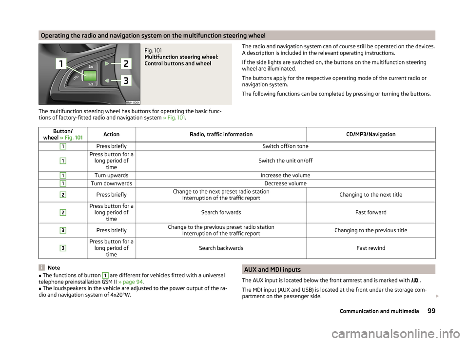
Operating the radio and navigation system on the multifunction steering wheelFig. 101
Multifunction steering wheel:
Control buttons and wheel
The multifunction steering wheel has buttons for operating the basic func-
tions of factory-fitted radio and navigation system » Fig. 101.
The radio and navigation system can of course still be operated on the devices.
A description is included in the relevant operating instructions.
If the side lights are switched on, the buttons on the multifunction steering wheel are illuminated.
The buttons apply for the respective operating mode of the current radio or
navigation system.
The following functions can be completed by pressing or turning the buttons.Button/
wheel » Fig. 101ActionRadio, traffic informationCD/MP3/Navigation1Press brieflySwitch off/on tone1Press button for a
long period of timeSwitch the unit on/off
1Turn upwardsIncrease the volume1Turn downwardsDecrease volume2Press brieflyChange to the next preset radio stationInterruption of the traffic reportChanging to the next title2Press button for along period of timeSearch forwardsFast forward
3Press brieflyChange to the previous preset radio station Interruption of the traffic reportChanging to the previous title3Press button for along period of timeSearch backwardsFast rewindNote■The functions of button 1 are different for vehicles fitted with a universal
telephone preinstallation GSM II » page 94.■
The loudspeakers in the vehicle are adjusted to the power output of the ra-
dio and navigation system of 4x20°W.
AUX and MDI inputs
The AUX input is located below the front armrest and is marked with
.
The MDI input (AUX and USB) is located at the front under the storage com-
partment on the passenger side. 99Communication and multimedia
Page 108 of 197
R - Reverse gear
Reverse gear can only be engaged when the vehicle is stationary and the en-
gine is at idling speed.
Depress the brake pedal and simultaneously press the shiftlock in the selector
lever grip before shifting to R from P or N.N
- Neutral
Power transmission to the drive wheels is interrupted in this mode.
D
- Mode for forwards travel (normal programme)
In mode D, the forward gears are automatically changed according to the en-
gine load, accelerator pedal actuation and driving speed.
S
- Mode for forwards travel (sports programme)
In mode S, the forward gears are shifted automatically up and down at higher
engine speeds than in mode D.
The shiftlock on the selector lever grip must be pressed when moving the se-
lector lever out of D mode into S mode.
Releasing selector lever from P or N modes (selector lever lock)
The selector lever is locked in the P and N modes to prevent the forwards trav-
el mode from being selected accidentally and setting the vehicle in motion.
The warning light lights up in the instrument cluster
» page 42.
The selector lever is released by depressing the brake pedal while simultane-
ously pressing the locking button in the selection lever grip.
The selector lever is not locked when shifted quickly through N (e.g. from R to
D ). This, for example, helps to rock out a vehicle that is stuck, e.g. in a bank of
snow. The selector lever lock will engage if the lever is in position N for more
than approximately 2 seconds without the brake pedal being depressed.
The selector lever is locked only when the vehicle is stationary and at speeds
up to 5 km/h.
Note
If you want to move the selector lever from mode P to mode D or vice versa,
move the selector lever quickly. This prevents modes R or N from being selec-
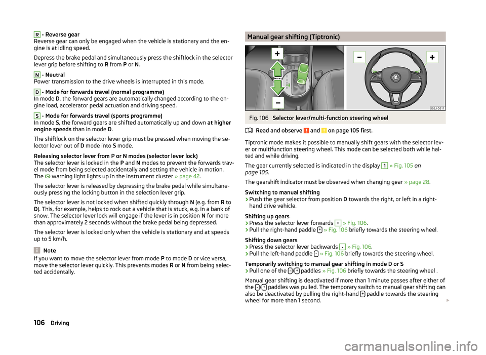
ted accidentally.Manual gear shifting (Tiptronic)Fig. 106
Selector lever/multi-function steering wheel
Read and observe
and on page 105 first.
Tiptronic mode makes it possible to manually shift gears with the selector lev-
er or multifunction steering wheel. This mode can be selected both while hal-
ted and while driving.
The gear currently selected is indicated in the display
1
» Fig. 105 on
page 105 .
The gearshift indicator must be observed when changing gear » page 28.
Switching to manual shifting
›
Push the gear selector from position D towards the right, or left in a right-
hand drive vehicle.
Shifting up gears
›
Press the selector lever forwards
+
» Fig. 106 .
›
Pull the right-hand paddle +
» Fig. 106 briefly towards the steering wheel.
Shifting down gears
›
Press the selector lever backwards
-
» Fig. 106 .
›
Pull the left-hand paddle -
» Fig. 106 briefly towards the steering wheel.
Temporarily switching to manual gear shifting in mode D or S
›
Pull one of the -/+ paddles
» Fig. 106 briefly towards the steering wheel .
Manual gear shifting is deactivated if more than 1 minute passes after either of
the -
/+ paddles was pulled. The temporary switch to manual gear shifting can
also be deactivated by pulling the right-hand + paddle towards the steering
wheel for more than 1 second.
106Driving
Page 120 of 197
›The speed will increase continuously, if the rocker button is pressed and held
in the RES position. Release the rocker button once the desired speed is
reached. The set speed is then stored in the memory.
Decreasing the speed›
The stored speed can be reduced by pressing rocker button
B
» Fig. 114 on
page 117 to the SET position.
›
The speed will decrease continuously, if the rocker button is pressed and
held in the SET position. Release the rocker button once the desired speed is
reached. The set speed is then stored in the memory.
›
If the rocker button is released at a speed below around 25 km/h, the speed
is not stored and the memory is erased. The speed must then be stored
again by pressing rocker button
B
to the SET position after increasing the
speed of the vehicle to more than around 25 km/h.
The speed can also be reduced by depressing the brake pedal, which tempora- rily deactivates the system.
Switching off temporarily
Read and observe
and on page 117 first.
The cruise control system can be temporarily switched off by pushing switch
A
» Fig. 114 on page 117 to the spring-loaded CANCEL position or by depress-
ing the brake or clutch pedal.
The set speed remains stored in the memory.
Briefly push rocker button
B
to the RES position to resume the set speed af-
ter the clutch or brake pedal is released.
Switching off completely
Read and observe
and on page 117 first.
›
Press switch
A
» Fig. 114 on page 117 to the right to the OFF position.
START-STOP
Introduction
This chapter contains information on the following subjects:
Operating conditions for the system
118
Operation
119System conditioned automatic start-up119Manually deactivating/activating119
Information messages
119
The START-STOP system (hereinafter referred to just as the system) reduces
fuel consumption and polluting emissions and CO 2 emissions by turning the
engine off, e.g. when stopping at traffic lights, and starting the engine again
when moving off.
WARNING■ Never let the vehicle roll with the engine switched off.■The brake servo unit and power steering only operate if the engine is run-
ning.
Operating conditions for the system
Fig. 115
Maxi DOT display: Engine is auto-
matically switched off / automat-
ic engine cut off is not possible
Read and observe on page 118 first.
For the system-dependent automatic engine shutdown to operate, the follow-
ing conditions must be met.
The driver's door is closed.
The driver has fastened the seat belt.
The bonnet is closed.
The driving speed exceeded 4 km/h after the last stop.
No trailer is coupled.
Some additional conditions for the system to function cannot be either influ-
enced or recognised by the driver. Therefore, the system can react differently
in situations which are identical from the driver's view.
118Driving
Page 168 of 197
Negative cable - colour coding in the majority of cases is black.
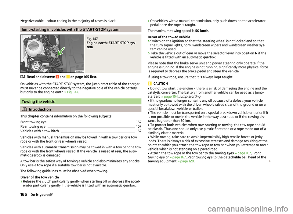
Jump-starting in vehicles with the START-STOP system
Fig. 147
Engine earth: START-STOP sys-
tem
Read and observe and on page 165 first.
On vehicles with the START-STOP system, the jump-start cable of the charger
must never be connected directly to the negative pole of the vehicle battery,
but only to the engine earth » Fig. 147.
Towing the vehicle
Introduction
This chapter contains information on the following subjects:
Front towing eye
167
Rear towing eye
167
Vehicles with a tow hitch
167
Vehicles with manual transmission may be towed in with a tow bar or a tow
rope or with the front or rear wheels raised.
Vehicles with automatic transmission may be towed in with a tow bar or a tow
rope or with the front wheels raised. If the vehicle is raised at rear, the auto-
matic gearbox is damaged!
A tow bar is the safest way of towing a vehicle and also minimises any shocks.
Only use a tow rope if a suitable tow bar is not available.
The following guidelines must be observed when towing.
Driver of the tow vehicle
›
Release the clutch particularly gently when starting off or depress the accel-
erator particularly gently if the vehicle is fitted with an automatic gearbox.
› On vehicles with a manual transmission, only push down on the accelerator
pedal once the rope is taught.
The maximum towing speed is 50 km/h.
Driver of the towed vehicle›
Switch on the ignition so that the steering wheel is not locked and so that
the turn signal lights, horn, windscreen wipers and windscreen washer sys-
tem can be used.
›
Take the vehicle out of gear or move the selector lever into position N if the
vehicle is fitted with an automatic gearbox.
Please note that the brake servo unit and power steering only operate if the
engine is running. If the engine is not running, significantly more physical force
is required to depress the brake pedal and steer the vehicle.
If using a tow rope, ensure that it is always kept taught.
CAUTION
■ Do not tow start the engine – there is a risk of damaging the engine and the
catalytic converter. The battery from another vehicle can be used as a jump-
start aid » page 164 , Jump-starting .■
If the gearbox no longer contains any oil because of a defect, your vehicle
must only be towed with the driven wheels raised clear of the ground or on a
special breakdown vehicle or trailer.
■
The vehicle must be transported on a special breakdown vehicle or trailer if it
is not possible to tow in the vehicle in the way described or if the towing dis-
tance is greater than 50 km.
■
To protect both vehicles when tow-starting or towing, the tow rope should
be elastic. Thus one should only use plastic fibre rope or a rope made out of a
similarly elastic material.
■
While towing, take care to avoid impermissibly high tensile forces or jerky
loads. There is always a risk of excessive stresses and damage resulting at the
points to which you attach the tow rope or tow bar when you attempt to tow a
vehicle which is not standing on a paved road.
■
Attach the tow rope or the tow bar to the towing eyes » page 167 , Front
towing eye or » page 167 , Rear towing eye to the detachable ball head of the
towing equipment » page 120 .
166Do-it-yourself
Page 171 of 197
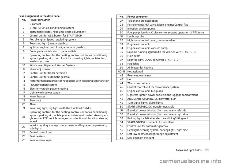
Fuse assignment in the dash panelNo.Power consumer1S-contact2START-STOP, air-conditioning system3Instrument cluster, headlamp beam adjustment4Control unit for ABS, button for START STOP5Petrol engine: Speed regulating system6Reversing light (manual gearbox)7Ignition, engine control unit, automatic gearbox8Brake pedal switch, clutch pedal switch9Operating controls for the heating, control unit for air conditioning
system, parking aid, control unit for cornering lights, radiator fan,
washing nozzles10Windscreen Wiper and Washer System11Mirror adjustment12Control unit for trailer detection13Control unit for automatic gearbox14Motor for halogen projector headlights with cornering light function15PDA navigation system16Electro-hydraulic power steering17Light switch power supply18Mirror heater19S-contact20Alarm21Reversing light, fog lights with the function CORNER
22
Operating controls for the heating, control unit for air conditioning
system, parking aid, mobile phone, instrument cluster, steering an-
gle sender, ESC, vehicle voltage control unit, multifunction steering
wheel23Interior lighting, storage compartment and luggage compartment,
side lights24Central control unit25Seat heaters26Rear window wiperNo.Power consumer27Telephone preinstallation28Petrol engine: AKF valve, Diesel engine: Control flap29Injection, coolant pump30Fuel pump, ignition, Cruise control system, operation of PTC relay31Lambda probe32High pressure fuel pump, pressure valve33Engine control unit34Engine control unit, vacuum pump35Daytime running lights/radio for vehicles with START-STOP36Main beam37Rear fog light, DC/DC converter START-STOP38Fog lights39Air blower for heating40-41Not assigned42Rear window heater43Horn44Windscreen wipers45Central control unit for convenience system46Engine control unit, fuel pump47Cigarette lighter, power socket in the luggage compartment48ABS, START-STOP (DC/DC) converter ESP49Turn signal lights, brake lights50START-STOP (DC/DC) transformer, radio51Electrical power window (front and rear) - left side52Electrical power window (front and rear) - right side53Parking light = left side, electrical sliding/tilting roof54START-STOP (instrument cluster), alarm55Control unit for automatic gearbox56Headlight cleaning system, parking light - right side57Left low beam, headlight range adjustment58Low beam on the right169Fuses and light bulbs
Page 172 of 197
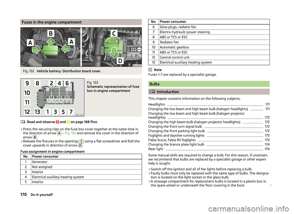
Fuses in the engine compartmentFig. 152
Vehicle battery: Distribution board cover.
Fig. 153
Schematic representation of fuse
box in engine compartment
Read and observe and on page 168 first.
› Press the securing clips on the fuse box cover together at the same time in
the direction of arrow
A
» Fig. 152 and remove the cover in the direction of
arrow
B
.
› Release the fixtures in the openings
C
using a flat screwdriver and fold the
cover upwards in direction of arrow
D
.
Fuse assignment in engine compartment
No.Power consumer1Generator2Not assigned3Interior4Electrical auxiliary heating system5InteriorNo.Power consumer6Glow plugs, radiator fan7Electro-hydraulic power steering8ABS or TCS or ESC9Radiator fan10Automatic gearbox11ABS or TCS or ESC12Central control unit13Electrical auxiliary heating system
Note
Fuses 1-7 are replaced by a specialist garage.
Bulbs
Introduction
This chapter contains information on the following subjects:
Headlights
171
Changing the low beam and high beam bulb (halogen headlights)
171
Changing the low beam and high beam bulb (halogen projector
headlights)
172
Changing the high beam bulb (halogen projector headlights)
172
Changing the front turn signal bulb
172
Changing the front parking light bulb
172
Foglights and daytime running lights
173
Fabia Scout, Fabia RS foglights
173
Changing the licence plate light bulb
174
Rear light
174
Some manual skills are required to change a bulb. For this reason, if uncertain,
we recommend that bulbs are replaced by a specialist garage or other expert
help is sought.
› Switch off the ignition and all of the lights before replacing a bulb.
› Faulty bulbs must only be replaced with the same type of bulbs. The designa-
tion is located on the light socket or the glass bulb.
› A stowage compartment for replacement bulbs is located in a plastic box in
the spare wheel or underneath the floor covering in the boot.
170Do-it-yourself