remove seats SKODA FABIA 2014 2.G / 5J Owner's Manual
[x] Cancel search | Manufacturer: SKODA, Model Year: 2014, Model line: FABIA, Model: SKODA FABIA 2014 2.G / 5JPages: 197, PDF Size: 13.56 MB
Page 13 of 197

WARNING (Continued)■The lock tongue should only be inserted into the lock which is the correct
one for your seat. Wrong use of the safety belt will reduce its capacity to
protect and the risk of injury increases.■
The slot of the belt tongue must not be blocked otherwise the belt
tongue will not lock in place properly.
■
Many layers of clothing and loose clothing (e. g. a winter coat over a jack-
et) do not allow you to be correctly seated and impairs proper operation of
the seat belts.
■
It is prohibited to use clamps or other objects to adjust seat belts (e. g. for
shortening the belts for smaller persons).
■
The seat belts for the rear seats can only fulfil their function reliably
when the seat backrests are correctly locked into position » page 66.
WARNINGInformation on the care and maintenance of the safety belts■The belt webbing must always be kept clean. Soiled belts may impair
proper operation of the inertia reel » page 134, Seat belts .■
The seat belts must not be removed or changed in any way. Do not at-
tempt to repair the seat belts yourself.
■
Check the condition of all the seat belts on a regular basis. If any damage
to the seat belts, seat belt connections, inertia reel or the lock is detected,
the seat belt concerned must be replaced by a specialist garage.
■
Damaged seat belts which have been subjected to stress in an accident
and were therefore stretched, must be replaced - this is best done by a
specialist garage. The anchorage points of the belts must also be inspec-
ted. The anchorage points for the belts should also be checked.
Note
The national legal requirements must be observed when using seat belts.The physical principle of a frontal collisionFig. 4
Driver without a fastened seat belt/rear seat passenger without a
fastened seat belt
Read and observe
on page 10 first.
As soon as the vehicle is moving, so-called kinetic energy (the energy of mo-
tion) is produced both in terms of the car as well as in terms of the occupants.
The magnitude of this kinetic energy depends essentially on the speed at
which the vehicle is travelling and on the weight of the vehicle including the
occupants. The greater the speed and weight increase, the greater the
amount of energy which has to be absorbed in the event of an accident.
The speed of the vehicle is the most important factor. Doubling the speed of
the vehicle from 25 km/h up to 50 km/hour increases the kinetic energy four
times.
The notion that it is possible to support your body with your hands in a minor
accident is incorrect. Even in a collision at only a low speed, the forces acting
on the body are such that it is no longer possible to support your body.
Even if you only drive at a speed of 30 km/h to 50 km/h, the forces that your body is exposed to in the event of an accident can exceed a ton (1000 kg).
For example, a person's weight of 80 kg “increases” at 50 km/h to 4.8 tons (4800 kg).
In the event of a frontal collision, occupants of the car not wearing a seat belt
are thrown forward and strike parts of the interior of the car, such as the
steering wheel, dash panel, windscreen in ways which cannot be control-
led » Fig. 4 -
. In certain circumstances you could even be thrown out of the
vehicle, which could cause life threatening or even fatal injuries.
11Seat belts
Page 21 of 197

›Check whether the 3
warning light in the mes-
sage in the centre of the dash panel does not light up after the ignition is
switched on.WARNING■ The driver is responsible for whether the airbag is switched on or switch-
ed off.■
Only switch off the airbag when the ignition is switched off! Otherwise a
fault can occur in the system for deactivating the airbag.
■
If the
warning light flashes, the front passenger airbag will not be
deployed in the event of an accident. Have the airbag system checked by a
specialist garage immediately.
■
The key cannot be inserted in the key switch while driving.
■ Shocks can cause the key to turn in the slot and trigger the airbag!
■ The airbag can be triggered unexpectedly in an accident - it may result
in injury or death!
CAUTION
An insufficiently folded out key bit can damage the key switch!Transporting children safely
Child seat
Introduction
This chapter contains information on the following subjects:
Use of a child seat on the front passenger seat
20
Child safety and side airbag
21
Classification of child seats
21
Use of child seats fastened with a seat belt
21
Children are generally safer on the rear seats than on the front passenger
seat.
In contrast to adults, the muscles and bone structure of children are not yet
fully developed. Thus children are exposed to increased risk of injury.
Children should be transported in accordance with the relevant statutory pro-
visions.
Child seats that comply with the ECE-R 44 standard must be used. The ECE-R
standard stands for: Economic Commission for Europe - Regulation.
Child seats that comply with the ECE-R 44 standard have a test seal that can-
not be removed: a large E within a circle with the test number below.
WARNING■ The national legal requirements must be observed when using child
seats.■
One should never carry children, and also not babies! - on one's lap.
■
Never leave children unattended in the vehicle. Certain outside climatic
conditions can cause life-threatening temperatures in the vehicle.
■
The child must be secured in the vehicle throughout the journey. Other-
wise, in the event of an accident, the child would be thrown through the
vehicle and as a result may suffer fatal injuries, and also injure other occu-
pants.
■
Children are exposed to an increased risk of injury in the event of an acci-
dent if they lean forward or adopt an incorrect seated position when the
vehicle is moving. This particularly applies to children who are transported
on the front passenger seat as they can suffer severe, or even fatal injuries
if the airbag system is deployed!
19Transporting children safely
Page 58 of 197
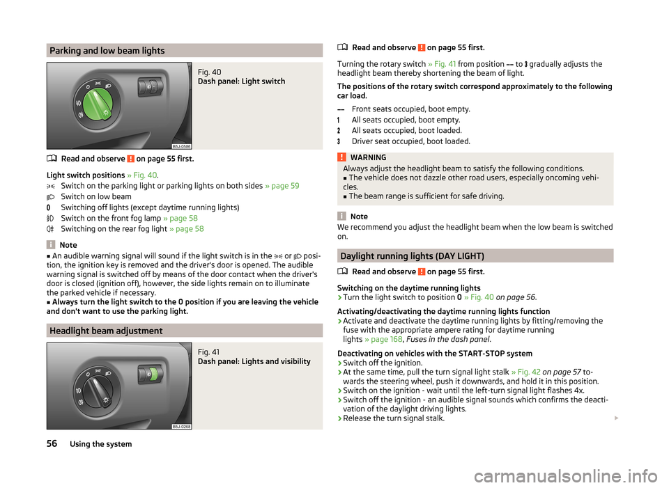
Parking and low beam lightsFig. 40
Dash panel: Light switch
Read and observe on page 55 first.
Light switch positions » Fig. 40 .
Switch on the parking light or parking lights on both sides » page 59
Switch on low beam
Switching off lights (except daytime running lights)
Switch on the front fog lamp » page 58
Switching on the rear fog light » page 58
Note
■
An audible warning signal will sound if the light switch is in the or posi-
tion, the ignition key is removed and the driver's door is opened. The audible
warning signal is switched off by means of the door contact when the driver's
door is closed (ignition off), however, the side lights remain on to illuminate
the parked vehicle if necessary.■
Always turn the light switch to the 0 position if you are leaving the vehicle
and don't want to use the parking light.
Headlight beam adjustment
Fig. 41
Dash panel: Lights and visibility
Read and observe on page 55 first.
Turning the rotary switch » Fig. 41 from position
to
gradually adjusts the
headlight beam thereby shortening the beam of light.
The positions of the rotary switch correspond approximately to the following
car load.
Front seats occupied, boot empty.
All seats occupied, boot empty.
All seats occupied, boot loaded.
Driver seat occupied, boot loaded.
WARNINGAlways adjust the headlight beam to satisfy the following conditions.■The vehicle does not dazzle other road users, especially oncoming vehi-
cles.■
The beam range is sufficient for safe driving.
Note
We recommend you adjust the headlight beam when the low beam is switched
on.
Daylight running lights (DAY LIGHT)
Read and observe
on page 55 first.
Switching on the daytime running lights
›
Turn the light switch to position 0 » Fig. 40 on page 56 .
Activating/deactivating the daytime running lights function
›
Activate and deactivate the daytime running lights by fitting/removing the
fuse with the appropriate ampere rating for daytime running
lights » page 168 , Fuses in the dash panel .
Deactivating on vehicles with the START-STOP system
›
Switch off the ignition.
›
At the same time, pull the turn signal light stalk » Fig. 42 on page 57 to-
wards the steering wheel, push it downwards, and hold it in this position.
›
Switch on the ignition - wait until the left-turn signal light flashes 4x.
›
Switch off the ignition - an audible signal sounds which confirms the deacti-
vation of the daylight driving lights.
›
Release the turn signal stalk.
56Using the system
Page 69 of 197
The luggage compartment can be increased in size by folding the seat backr-
ests forward. The seat backrests can be folded forward individually on vehicles
with divided rear seats.
Folding forward›
Before folding the rear seats forwards, adapt the position of the front seats
in such a way that they are not damaged by the folded rear seats.
›
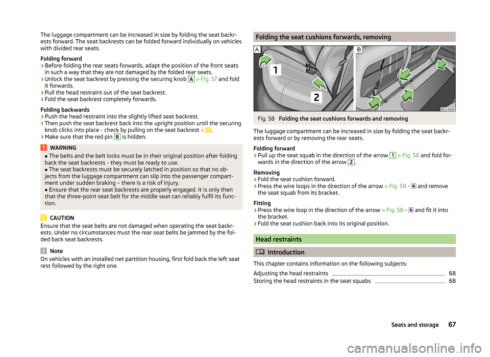
Unlock the seat backrest by pressing the securing knob
A
» Fig. 57 and fold
it forwards.
›
Pull the head restraint out of the seat backrest.
›
Fold the seat backrest completely forwards.
Folding backwards
›
Push the head restraint into the slightly lifted seat backrest.
›
Then push the seat backrest back into the upright position until the securing
knob clicks into place - check by pulling on the seat backrest » .
›
Make sure that the red pin
B
is hidden.
WARNING■
The belts and the belt locks must be in their original position after folding
back the seat backrests - they must be ready to use.■
The seat backrests must be securely latched in position so that no ob-
jects from the luggage compartment can slip into the passenger compart-
ment under sudden braking – there is a risk of injury.
■
Ensure that the rear seat backrests are properly engaged. It is only then
that the three-point seat belt for the middle seat can reliably fulfil its func-
tion.
CAUTION
Ensure that the seat belts are not damaged when operating the seat backr-
ests. Under no circumstances must the rear seat belts be jammed by the fol-
ded back seat backrests.
Note
On vehicles with an installed net partition housing, first fold back the left seat
rest followed by the right one.Folding the seat cushions forwards, removingFig. 58
Folding the seat cushions forwards and removing
The luggage compartment can be increased in size by folding the seat backr-
ests forward or by removing the rear seats.
Folding forward
›
Pull up the seat squab in the direction of the arrow
1
» Fig. 58 and fold for-
wards in the direction of the arrow
2
.
Removing
›
Fold the seat cushion forward.
›
Press the wire loops in the direction of the arrow » Fig. 58 -
and remove
the seat squab from its bracket.
Fitting
›
Press the wire loop in the direction of the arrow » Fig. 58 -
and fit it into
the bracket.
›
Fold the seat cushion back into its original position.
Head restraints
Introduction
This chapter contains information on the following subjects:
Adjusting the head restraints
68
Storing the head restraints in the seat squabs
6867Seats and storage
Page 70 of 197
Adjusting the head restraintsFig. 59
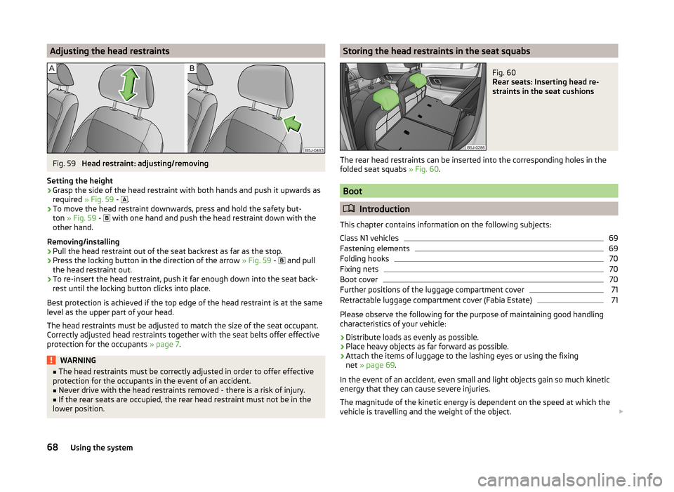
Head restraint: adjusting/removing
Setting the height
›
Grasp the side of the head restraint with both hands and push it upwards as
required » Fig. 59 -
.
›
To move the head restraint downwards, press and hold the safety but-
ton » Fig. 59 -
with one hand and push the head restraint down with the
other hand.
Removing/installing
›
Pull the head restraint out of the seat backrest as far as the stop.
›
Press the locking button in the direction of the arrow » Fig. 59 -
and pull
the head restraint out.
›
To re-insert the head restraint, push it far enough down into the seat back-
rest until the locking button clicks into place.
Best protection is achieved if the top edge of the head restraint is at the same
level as the upper part of your head.
The head restraints must be adjusted to match the size of the seat occupant.
Correctly adjusted head restraints together with the seat belts offer effective
protection for the occupants » page 7.
WARNING■
The head restraints must be correctly adjusted in order to offer effective
protection for the occupants in the event of an accident.■
Never drive with the head restraints removed - there is a risk of injury.
■
If the rear seats are occupied, the rear head restraint must not be in the
lower position.
Storing the head restraints in the seat squabsFig. 60
Rear seats: Inserting head re-
straints in the seat cushions
The rear head restraints can be inserted into the corresponding holes in the folded seat squabs » Fig. 60.
Boot
Introduction
This chapter contains information on the following subjects:
Class N1 vehicles
69
Fastening elements
69
Folding hooks
70
Fixing nets
70
Boot cover
70
Further positions of the luggage compartment cover
71
Retractable luggage compartment cover (Fabia Estate)
71
Please observe the following for the purpose of maintaining good handling
characteristics of your vehicle:
›
Distribute loads as evenly as possible.
›
Place heavy objects as far forward as possible.
›
Attach the items of luggage to the lashing eyes or using the fixing
net » page 69 .
In the event of an accident, even small and light objects gain so much kinetic
energy that they can cause severe injuries.
The magnitude of the kinetic energy is dependent on the speed at which the
vehicle is travelling and the weight of the object.
68Using the system
Page 73 of 197
WARNINGNo objects should be placed on the boot cover, the vehicle occupants could
be endangered if there is sudden braking or the vehicle collides with some-
thing.
CAUTION
■ When closing the boot lid, jamming and damage to the luggage compartment
cover or the side trim panel can occur if handled in an unprofessional way. The
following guidelines must be observed. ■ The recesses in the cover 3
» Fig. 64 must lock in the holders in the side
trim panel
2
.
■ The items which are transported must not exceed the height of the lug-
gage compartment cover. ■ The cover must not be jammed in the seal of the boot lid when it is in the
opened position.
■ There must be no object in the gap between the opened cover and the rear
backrest.
Note
Opening the boot lid also lifts up the boot cover.
Further positions of the luggage compartment cover
Fig. 65
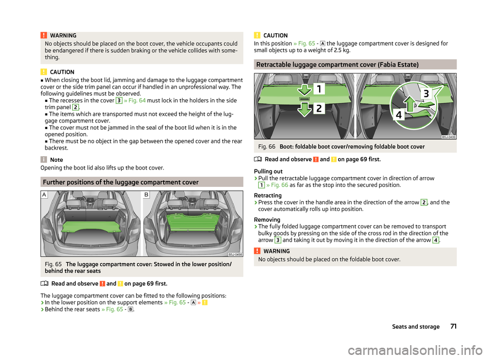
The luggage compartment cover: Stowed in the lower position/
behind the rear seats
Read and observe
and on page 69 first.
The luggage compartment cover can be fitted to the following positions:› In the lower position on the support elements
» Fig. 65 -
»
› Behind the rear seats
» Fig. 65 -
.
CAUTIONIn this position
» Fig. 65 - the luggage compartment cover is designed for
small objects up to a weight of 2.5 kg.
Retractable luggage compartment cover (Fabia Estate)
Fig. 66
Boot: foldable boot cover/removing foldable boot cover
Read and observe
and on page 69 first.
Pulling out
›
Pull the retractable luggage compartment cover in direction of arrow
1
» Fig. 66 as far as the stop into the secured position.
Retracting
›
Press the cover in the handle area in the direction of the arrow
2
, and the
cover automatically rolls up into position.
Removing
›
The fully folded luggage compartment cover can be removed to transport
bulky goods by pressing on the side of the cross rod in the direction of the
arrow
3
and taking it out by moving it in the direction of the arrow
4
.
WARNINGNo objects should be placed on the foldable boot cover.71Seats and storage
Page 75 of 197
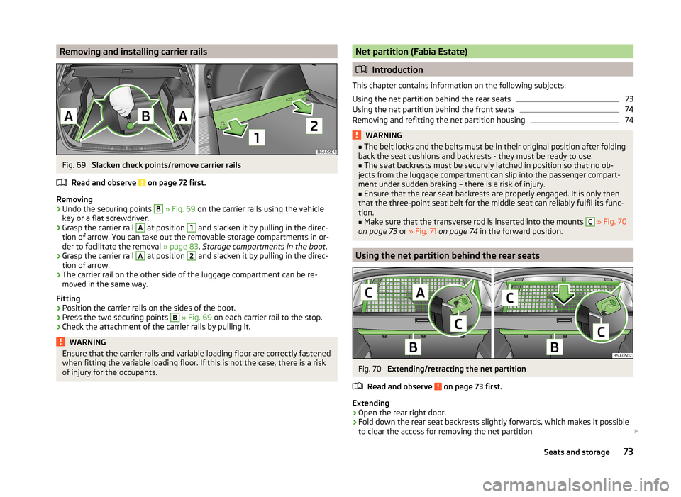
Removing and installing carrier railsFig. 69
Slacken check points/remove carrier rails
Read and observe
on page 72 first.
Removing
›
Undo the securing points
B
» Fig. 69 on the carrier rails using the vehicle
key or a flat screwdriver.
›
Grasp the carrier rail
A
at position
1
and slacken it by pulling in the direc-
tion of arrow. You can take out the removable storage compartments in or-
der to facilitate the removal » page 83, Storage compartments in the boot .
›
Grasp the carrier rail
A
at position
2
and slacken it by pulling in the direc-
tion of arrow.
›
The carrier rail on the other side of the luggage compartment can be re-
moved in the same way.
Fitting
›
Position the carrier rails on the sides of the boot.
›
Press the two securing points
B
» Fig. 69 on each carrier rail to the stop.
›
Check the attachment of the carrier rails by pulling it.
WARNINGEnsure that the carrier rails and variable loading floor are correctly fastened
when fitting the variable loading floor. If this is not the case, there is a risk
of injury for the occupants.Net partition (Fabia Estate)
Introduction
This chapter contains information on the following subjects:
Using the net partition behind the rear seats
73
Using the net partition behind the front seats
74
Removing and refitting the net partition housing
74WARNING■ The belt locks and the belts must be in their original position after folding
back the seat cushions and backrests - they must be ready to use.■
The seat backrests must be securely latched in position so that no ob-
jects from the luggage compartment can slip into the passenger compart-
ment under sudden braking – there is a risk of injury.
■
Ensure that the rear seat backrests are properly engaged. It is only then
that the three-point seat belt for the middle seat can reliably fulfil its func-
tion.
■
Make sure that the transverse rod is inserted into the mounts
C
» Fig. 70
on page 73 or » Fig. 71 on page 74 in the forward position.
Using the net partition behind the rear seats
Fig. 70
Extending/retracting the net partition
Read and observe
on page 73 first.
Extending
›
Open the rear right door.
›
Fold down the rear seat backrests slightly forwards, which makes it possible
to clear the access for removing the net partition.
73Seats and storage
Page 76 of 197
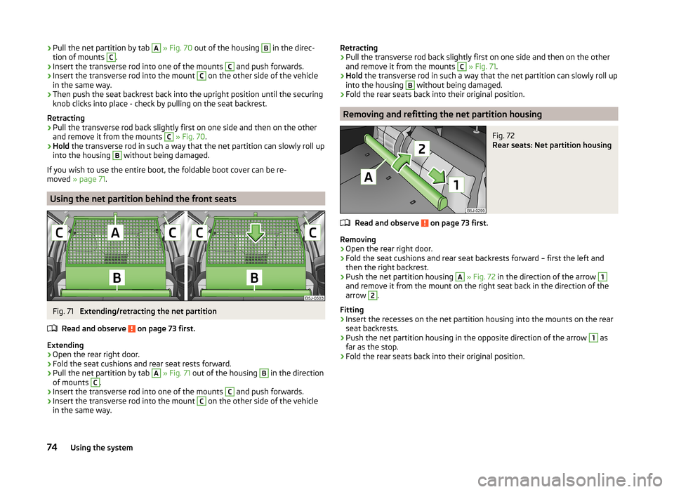
›Pull the net partition by tab A
» Fig. 70 out of the housing B in the direc-
tion of mounts C.›
Insert the transverse rod into one of the mounts
C
and push forwards.
›
Insert the transverse rod into the mount
C
on the other side of the vehicle
in the same way.
›
Then push the seat backrest back into the upright position until the securing
knob clicks into place - check by pulling on the seat backrest.
Retracting
›
Pull the transverse rod back slightly first on one side and then on the other
and remove it from the mounts
C
» Fig. 70 .
›
Hold the transverse rod in such a way that the net partition can slowly roll up
into the housing
B
without being damaged.
If you wish to use the entire boot, the foldable boot cover can be re-
moved » page 71 .
Using the net partition behind the front seats
Fig. 71
Extending/retracting the net partition
Read and observe
on page 73 first.
Extending
›
Open the rear right door.
›
Fold the seat cushions and rear seat rests forward.
›
Pull the net partition by tab
A
» Fig. 71 out of the housing
B
in the direction
of mounts
C
.
›
Insert the transverse rod into one of the mounts
C
and push forwards.
›
Insert the transverse rod into the mount
C
on the other side of the vehicle
in the same way.
Retracting›Pull the transverse rod back slightly first on one side and then on the other
and remove it from the mounts C
» Fig. 71 .
›
Hold the transverse rod in such a way that the net partition can slowly roll up
into the housing
B
without being damaged.
›
Fold the rear seats back into their original position.
Removing and refitting the net partition housing
Fig. 72
Rear seats: Net partition housing
Read and observe on page 73 first.
Removing
›
Open the rear right door.
›
Fold the seat cushions and rear seat backrests forward – first the left and then the right backrest.
›
Push the net partition housing
A
» Fig. 72 in the direction of the arrow
1
and remove it from the mount on the right seat back in the direction of the
arrow
2
.
Fitting
›
Insert the recesses on the net partition housing into the mounts on the rear
seat backrests.
›
Push the net partition housing in the opposite direction of the arrow
1
as
far as the stop.
›
Fold the rear seats back into their original position.
74Using the system
Page 77 of 197
Bicycle carrier in the luggage compartment
Introduction
This chapter contains information on the following subjects:
Install cross member
75
Install bicycle carrier
75
Put bicycle into the bicycle carrier
76
Secure the stability of the bicycles with a belt
76WARNINGWhen transporting bicycles, ensuring the safety of the passengers is para-
mount.
CAUTION
Take care handling the bicycle - there is a risk of damaging the vehicle.
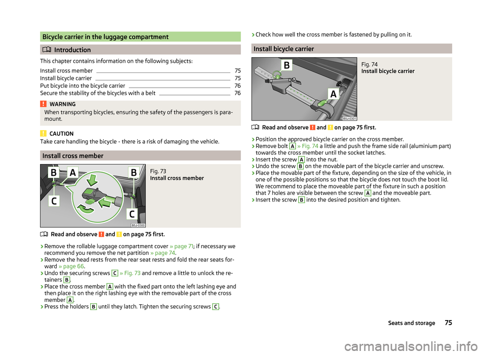
Install cross member
Fig. 73
Install cross member
Read and observe and on page 75 first.
›
Remove the rollable luggage compartment cover » page 71; if necessary we
recommend you remove the net partition » page 74.
›
Remove the head rests from the rear seat rests and fold the rear seats for-
ward » page 66 .
›
Undo the securing screws
C
» Fig. 73 and remove a little to unlock the re-
tainers
B
.
›
Place the cross member
A
with the fixed part onto the left lashing eye and
then place it on the right lashing eye with the removable part of the cross
member
A
.
›
Press the holders
B
until they latch. Tighten the securing screws
C
.
› Check how well the cross member is fastened by pulling on it.
Install bicycle carrier
Fig. 74
Install bicycle carrier
Read and observe and on page 75 first.
›
Position the approved bicycle carrier on the cross member.
›
Remove bolt
A
» Fig. 74 a little and push the frame side rail (aluminium part)
towards the cross member until the socket latches.
›
Insert the screw
A
into the nut.
›
Undo the screw
B
on the movable part of the bicycle carrier and unscrew.
›
Place the movable part of the fixture, depending on the size of the vehicle, in
one of the possible positions so that the bicycle does not touch the boot lid.
We recommend to place the moveable part of the fixture in such a position
that 7 holes are visible between the screw
A
and the moveable part.
›
Insert the screw
B
into the desired position and tighten.
75Seats and storage
Page 78 of 197
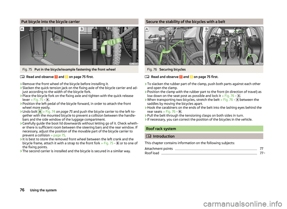
Put bicycle into the bicycle carrierFig. 75
Put in the bicycle/example fastening the front wheel
Read and observe
and on page 75 first.
›
Remove the front wheel of the bicycle before installing it.
›
Slacken the quick tension jack on the fixing axle of the bicycle carrier and ad-
just according to the width of the bicycle fork.
›
Place the bicycle fork on the fixing axle and tighten with the quick release
lever » Fig. 75 -
.
›
Position the left pedal of the bicycle forward, in order to attach the front
wheel more easily.
›
Undo bolt
A
» Fig. 74 on page 75 and push the bicycle carrier to the left to-
gether with the mounted bicycle to prevent a collision between the handle-
bars and the side window of the luggage compartment.
›
Carefully guide the boot lid downwards without letting go of it. Check wheth-
er there is sufficient room between the steering bars and the rear window. If
necessary, adjust the position of the movable part of the bicycle carrier to
prevent a collision » page 75.
›
It is best to store the removed front wheel between the left crank and the
bicycle frame, attach it with a strap to the front fork » Fig. 75 -
or to one of
the fixing points.
›
The second carrier is installed and the bicycle is secured in a similar way.
Secure the stability of the bicycles with a beltFig. 76
Securing bicycles
Read and observe
and on page 75 first.
›
To slacken the rubber part of the clamp, push both parts against each other
and open the clamp.
›
Position the clamp with the rubber part to the front (in direction of travel) as
low down on the seat post as possible and lock it » Fig. 76 -
.
›
When transporting two bicycles, stretch the belt
» Fig. 76 -
between the
saddles by moving the bicycles apart.
›
Hook the carabiners on the ends of the belt into the lashing eyes behind the
rear seats » Fig. 76 -
.
›
Pull the belt through the tensioning clasps on both sides in turn.
›
If necessary, you can correct the position of the bicycles in the vehicle.
Roof rack system
Introduction
This chapter contains information on the following subjects:
Attachment points
77
Roof load
77
76Using the system