tow bar SKODA FABIA 2014 2.G / 5J Owner's Manual
[x] Cancel search | Manufacturer: SKODA, Model Year: 2014, Model line: FABIA, Model: SKODA FABIA 2014 2.G / 5JPages: 197, PDF Size: 13.56 MB
Page 84 of 197
WARNINGNever put heavy items in the map pockets – risk of injury.
CAUTION
Do not put any large items such as bottles or sharp objects into the map pock-
ets, as the pockets and the seat covers could be damaged.
Glasses storage box
Fig. 87
Detail of the headliner: Glasses
storage box
Read and observe on page 80 first.
›
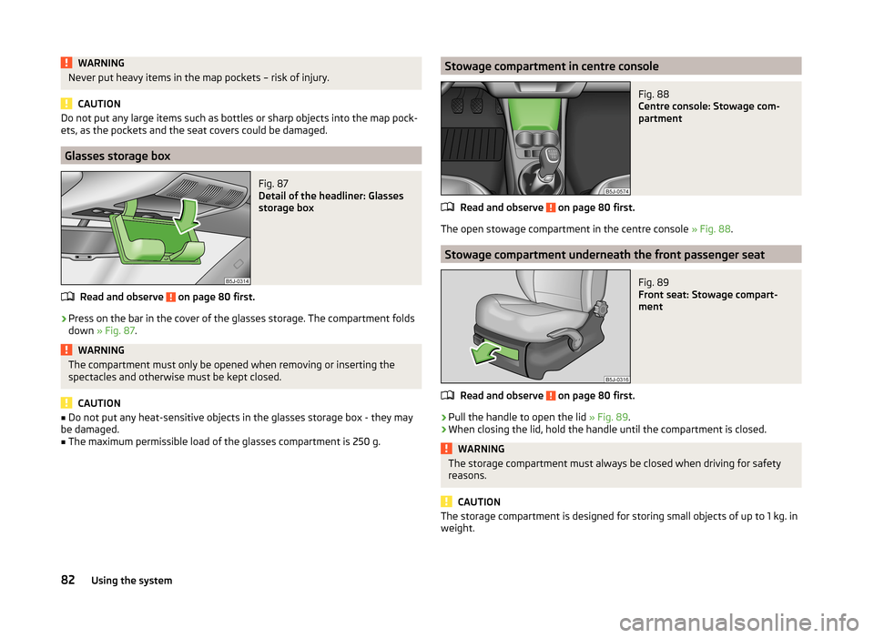
Press on the bar in the cover of the glasses storage. The compartment folds
down » Fig. 87 .
WARNINGThe compartment must only be opened when removing or inserting the
spectacles and otherwise must be kept closed.
CAUTION
■ Do not put any heat-sensitive objects in the glasses storage box - they may
be damaged.■
The maximum permissible load of the glasses compartment is 250 g.
Stowage compartment in centre consoleFig. 88
Centre console: Stowage com-
partment
Read and observe on page 80 first.
The open stowage compartment in the centre console » Fig. 88.
Stowage compartment underneath the front passenger seat
Fig. 89
Front seat: Stowage compart-
ment
Read and observe on page 80 first.
›
Pull the handle to open the lid » Fig. 89.
›
When closing the lid, hold the handle until the compartment is closed.
WARNINGThe storage compartment must always be closed when driving for safety
reasons.
CAUTION
The storage compartment is designed for storing small objects of up to 1 kg. in
weight.82Using the system
Page 118 of 197
Parking aid
Introduction
This chapter contains information on the following subjects:
Function
116
Activation/deactivation
116WARNING■ The parking aid is not a substitute for the driver paying proper attention
and it is always the driver's responsibility to take care when reversing the
vehicle or carrying out similar manoeuvres. Pay particular attention to small
children and animals as they are not recognised by the parking aid sensors.■
Before reversing, you should make sure that there are no small obstacles,
such as rocks, thin posts, trailer drawbars etc. behind your vehicle. Such ob-
stacles may not be recognised by the parking aid sensors.
■
Under certain circumstances, surfaces of certain objects and types of
clothing cannot reflect the system signals. Thus, these objects or people
who wear such clothing are not recognised by the System sensors.
■
External sound sources can have a detrimental effect on the system. Un-
der adverse conditions, this may cause objects or people to not be recog-
nised by the system.
CAUTION
■ If a warning signal sounds for about 3 seconds after activating the system
and there is no obstacle close to your car, this indicates a system fault. Have
the fault rectified by a specialist garage.■
The sensors must be kept clean (free of ice, etc.) to enable the parking aid to
operate properly.
■
Under adverse weather conditions (heavy rain, water vapour, very low or
high temperatures etc.) system function may be limited.
■
Additionally fitted modules, such as a bicycle rack, can impair the function of
the parking aid.
FunctionFig. 113
Parking aid: Range of sensors
Read and observe and on page 116 first.
The parking aid (referred to below solely as system) only works when the igni-
tion is switched on.
The system supports the driver via audible signals, via the display on the radio
or via the factory-installed navigation system when parking and manoeu-
vring » Radio user guide, Navigation system user guide.
The system uses ultrasound waves to calculate the distance between the
bumper and an obstacle. The ultrasonic sensors are integrated in the rear
bumper.
Range of sensors
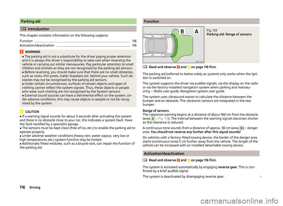
The clearance warning begins at a distance of about 160 cm from the obstacle
(area
A
» Fig. 113 ). The interval between the warning signals becomes shorter
as the clearance is reduced.
A continuous tone sounds from a distance of approx. 30 cm (area
B
) - danger
area. You should not reverse any further after this signal sounds!
On vehicles with a factory-fitted towing device, the border of the danger area
starts (continuous tone) 5 cm further away from the vehicle. The length of the
vehicle can be increased with an installed detachable towing device.
Activation/deactivation
Read and observe
and on page 116 first.
The system is activated automatically by engaging reverse gear. This is con-
firmed by a brief audible signal.
The system is deactivated by disengaging reverse gear.
116Driving
Page 122 of 197
Error: start-stop system
ERROR START-STOP
A system error is present. Seek help from a specialist garage.Towing a trailer
Towing device
Introduction
This chapter contains information on the following subjects:
Description
121
Adjusting the ready position
121
Fitting the ball head
122
Check proper fitting
122
Removing the ball head
123
Use and care
123
If your vehicle has already been factory-fitted with towing equipment or is fit-
ted with towing equipment from ŠKODA Original Accessories, then it meets all
of the technical requirements and national legal provisions for towing a trailer.
Your vehicle is fitted with a 13-pin power socket for the electrical connection
between the vehicle and trailer. If the trailer that is to be towed has a 7-pin
connector , you can use a suitable adapter from ŠKODA Original Accessories.
The maximum trailer drawbar load is 50 kg.
WARNING■
Check that the ball head is seated correctly and is secured in the mount-
ing recess before starting any journey.■
Do not use the ball head if it is not correctly inserted in the mounting re-
cess.
■
Do not use the towing equipment if it is damaged or incomplete.
■
Do not modify or adapt the towing equipment in any way.
■
Never release the ball head while the trailer is still coupled.
CAUTION
Take care with the ball head to avoid damaging the paintwork on the bumper.120Driving
Page 124 of 197
Fitting the ball headFig. 120
Insert the ball head/lock the lock, and put the lock cover on
Read and observe
and on page 120 first.
›
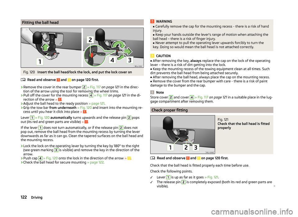
Remove the cover in the rear bumper
2
» Fig. 117 on page 121 in the direc-
tion of the arrow using the tool for removing the wheel trims.
›
Pull off the cover for the mounting recess
4
» Fig. 117 on page 121 in the di-
rection of the arrow » .
›
Adjust the ball head to the ready position » page 121.
›
Grip the tow bar from underneath » Fig. 120 and insert into the mounting re-
cess until you hear it click into place » .
Lever
1
» Fig. 120 automatically turns upwards and the release pin
2
pops
out (its red and green parts are visible) » .
If the lever
1
does not turn automatically, or if the release pin
2
does not
pop out, remove the ball head from the mounting recess by turning the lever
downwards as far as it can go. Clean the tapered surfaces on the ball head and
the mounting recess.
›
Lock the lock on the operating lever by turning the key by 180° to the right
(see green marking
3
is visible) and remove the key in the direction of the
arrow.
›
Push cap
4
» Fig. 120 onto the lock in the direction of the arrow » .
›
Check the ball head for secure mounting » page 122.
WARNING■
Carefully remove the cap for the mounting recess - there is a risk of hand
injury.■
Keep your hands outside the lever's range of motion when attaching the
ball head – there is a risk of finger injury.
■
Never attempt to pull the operating lever upwards forcibly to turn the
key. Doing so would mean the ball head is not attached correctly.
CAUTION
■ After removing the key, always replace the cap on the lock of the operating
lever – there is a risk of dirt getting into the lock.■
Keep the mounting recess of the towing equipment clean at all times. Such
dirt prevents the ball head from being attached securely.
■
After removing the ball head, always place the cap on the mounting recess.
■
Remove the cover from the rear bumper with care - there is a risk of paint
damage to the bumper and the cap.
Note
Store cover 2 and cover 4 » Fig. 117 on page 121 in a suitable place in the lug-
gage compartment after removing them.
Check proper fitting
Fig. 121
Check that the ball head is fitted
properly
Read and observe and on page 120 first.
Check that the ball head is fitted properly each time before use.
Check the following points. Lever
1
is up as far as it goes » Fig. 121.
The release pin
2
is completely exposed (both its red and green parts are
visible).
122Driving
Page 125 of 197
The key is removed.
The cap 3
is on the lock of the operating lever.
The ball head does not come out of the mounting recess even after heavy
“shaking”.WARNINGDo not use the towing equipment unless the ball head was properly locked.
Removing the ball head
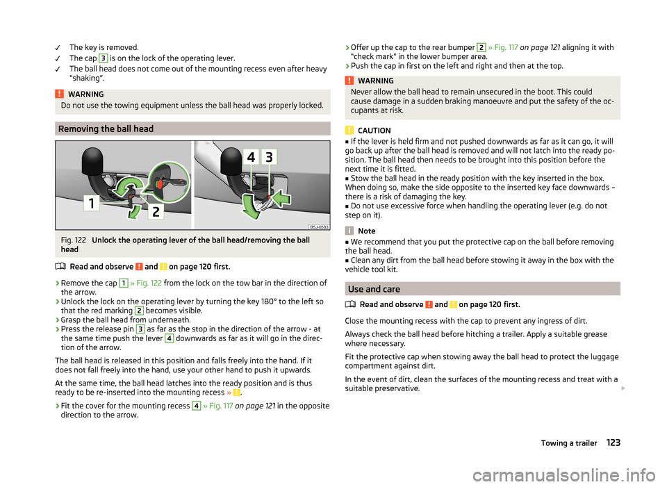
Fig. 122
Unlock the operating lever of the ball head/removing the ball
head
Read and observe
and on page 120 first.
›
Remove the cap
1
» Fig. 122 from the lock on the tow bar in the direction of
the arrow.
›
Unlock the lock on the operating lever by turning the key 180° to the left so
that the red marking
2
becomes visible.
›
Grasp the ball head from underneath.
›
Press the release pin
3
as far as the stop in the direction of the arrow - at
the same time push the lever
4
downwards as far as it will go in the direc-
tion of the arrow.
The ball head is released in this position and falls freely into the hand. If it
does not fall freely into the hand, use your other hand to push it upwards.
At the same time, the ball head latches into the ready position and is thus
ready to be re-inserted into the mounting recess »
.
›
Fit the cover for the mounting recess
4
» Fig. 117 on page 121 in the opposite
direction to the arrow.
›
Offer up the cap to the rear bumper 2
» Fig. 117 on page 121 aligning it with
“check mark” in the lower bumper area.›
Push the cap in first on the left and right and then at the top.
WARNINGNever allow the ball head to remain unsecured in the boot. This could
cause damage in a sudden braking manoeuvre and put the safety of the oc- cupants at risk.
CAUTION
■ If the lever is held firm and not pushed downwards as far as it can go, it will
go back up after the ball head is removed and will not latch into the ready po-
sition. The ball head then needs to be brought into this position before the
next time it is fitted.■
Stow the ball head in the ready position with the key inserted in the box.
When doing so, make the side opposite to the inserted key face downwards –
there is a risk of damaging the key.
■
Do not use excessive force when handling the operating lever (e.g. do not
step on it).
Note
■ We recommend that you put the protective cap on the ball before removing
the ball head.■
Clean any dirt from the ball head before stowing it away in the box with the
vehicle tool kit.
Use and care
Read and observe
and on page 120 first.
Close the mounting recess with the cap to prevent any ingress of dirt.
Always check the ball head before hitching a trailer. Apply a suitable grease where necessary.
Fit the protective cap when stowing away the ball head to protect the luggage
compartment against dirt.
In the event of dirt, clean the surfaces of the mounting recess and treat with a
suitable preservative.
123Towing a trailer
Page 126 of 197
CAUTIONApply grease to the upper part of the mounting recess. Make sure you do not
remove any grease.
Trailer
Introduction
This chapter contains information on the following subjects:
Loading a trailer
124
Towing a trailer
124
Anti-theft alarm system
125WARNINGAlways drive particularly carefully with the trailer.
Loading a trailer
Read and observe
on page 124 first.
The vehicle/trailer combination must be balanced, whereby the maximum per-
missible drawbar load must be utilised. If the drawbar load is too low, it jeop-
ardises the performance of the vehicle/trailer combination.
Distribution of the load
Distribute the load in the trailer in such a way that heavy items are located as
close to the axle as possible. Secure the items from slipping.
The distribution of the weight is very poor if your vehicle is unladen and the
trailer is laden. Maintain a particularly low speed if you cannot avoid driving
with this combination.
Tyre pressure
Correct the tyre inflation pressure on your vehicle for a “full load” » page 151,
Tyre service life .
Trailer load
The permissible trailer load must not be exceeded under any circumstan-
ces » page 176 , Technical data .
The trailer loads specified apply only to altitudes up to 1 000 metres above
mean sea level.
The engine output falls as altitude increases, as does the ability to climb.
Therefore, for every additional 1000 m in height (or part), the maximum per-
missible towed weight must be reduced by 10 %.
The towed weight comprises the actual weights of the (loaded) towing vehicle and the (loaded) trailer.
The trailer and drawbar load information on the type plate of the towing
equipment are merely test data for the towing equipment. The vehicle-specific
values are detailed in the vehicle documents.WARNING■ Do not exceed the maximum permissible axle and drawbar load and the
maximum permissible total or towed weight of the vehicle and the trailer –
there is the risk of an accident and serious injury.■
Slipping loads can significantly affect the stability and safety of the vehi-
cle/trailer combination – there is the risk of an accident and serious injury.
Towing a trailer
Read and observe
on page 124 first.
Exterior mirrors
You have to have additional exterior mirrors fitted if you are not able to see
the traffic behind the trailer with the standard rear-view mirrors. National legal
requirements must be observed.
Headlights
The front of the vehicle can be lifted when a trailer is being towed and the
headlights can dazzle other road users.
Adjust the headlight setting on the headlight range control » page 56, Head-
light beam adjustment .
Driving speed
For safety reasons, do not drive faster than 80 km/h when towing a trailer.
Immediately reduce your speed as soon as even the slightest swaying of the
trailer is detected. Never attempt to stop the trailer from “swaying” by acceler-
ating.
Brakes
Apply the brakes in good time! If the trailer is fitted with a trailer brake, apply
the brakes gently at first, then brake firmly. This will avoid brake jolts resulting
from the trailer wheels locking.
124Driving
Page 162 of 197
WARNING (Continued)■Secure the base plate of the lifting jack with suitable means to prevent
possible moving. A soft and slippery ground under the base plate may move
the lifting jack, causing the vehicle to fall down. It is therefore always nec-
essary to place the lifting jack on a solid surface or use a wide and stable
base. Use a non-slip base (e.g. a rubber foot mat) if the surface is smooth,
such as cobbled stones, tiled floor, etc.■
Only attach the lifting jack to the attachment points provided for this pur-
pose.
■
Always raise the vehicle with the doors closed.
■
Never position any body parts, such as arms or legs under the vehicle,
while the vehicle is raised with a lifting jack.
■
Never start the engine with the vehicle sitting on the raised jack – there
is a risk of injury.
WARNINGInformation on the wheel bolts■The wheel bolts must be clean and must turn easily. Never treat them
with grease or oil.■
The prescribed tightening torque of the wheel bolts for steel and light al-
loy wheels is 120 Nm.
■
If the wheel bolts are tightened to a too low tightening torque, the rim
can come loose when the car is moving – risk of accident! A tightening tor-
que which is too high can damage the bolts and threads and this can result
in permanent deformation of the contact surfaces on the rim.
■
In case of incorrect treatment of the wheel bolts, the wheel can loosen
when the car is moving – risk of accident!
Note
The national legal requirements must be observed when changing a wheel.
Preparation
Read and observe
on page 159 first.
Always change a wheel on a level surface as far as possible.
The following steps must be carried out before actually changing the wheel:
›
Have all the occupants get out. The passengers should not stand on the
road (instead they should remain behind a crash barrier, for instance) while
the wheel is being changed.
› Switch off the engine.›Move the gearshift lever into
Neutral or move the selector lever for the auto-
matic gearbox into position P.›
Apply the handbrake firmly.
›
Uncouple any trailer.
›
Remove the vehicle tool kit » page 159 and the spare wheel » page 155 ,
Spare and back-up wheel from the boot.
Changing a wheel
Read and observe
on page 159 first.
›
Remove the full wheel trim » page 156 or caps » page 156 .
›
First of all slacken the anti-theft wheel bolt and then the other wheel
bolts » page 161 .
›
Jack up the vehicle until the wheel that needs changing is clear of the
ground » page 161 .
›
Unscrew the wheel bolts and place them on a clean surface (cloth, paper,
etc.).
›
Remove the wheel carefully.
›
Attach the spare wheel and slightly screw on the wheel bolts.
›
Lower the vehicle.
›
Tighten the opposite wheel bolts alternately (cross-wise) with the wheelwrench. Tighten the anti-theft wheel bolt last » page 161.
›
Reinstall the wheel trim/wheel trim cap or the caps.
Note
■
All bolts must be clean and must turn easily.■Under no circumstances grease or oil the wheel bolts!■
When fitting unidirectional tyres, ensure that the direction of rotation is cor-
rect » page 154 , Unidirectional tyres .
Subsequent steps
Read and observe
on page 159 first.
The following steps must also be performed after changing the wheel.
›
Stow and attach the replaced wheel in the spare wheel well using a special
screw » page 155 , Spare and back-up wheel .
›
Stow the tool kit in the space provided and secure using the strap.
›
Check the tyre pressure on the installed spare wheel as soon as possible.
160Do-it-yourself
Page 168 of 197
Negative cable - colour coding in the majority of cases is black.
Jump-starting in vehicles with the START-STOP system
Fig. 147
Engine earth: START-STOP sys-
tem
Read and observe and on page 165 first.
On vehicles with the START-STOP system, the jump-start cable of the charger
must never be connected directly to the negative pole of the vehicle battery,
but only to the engine earth » Fig. 147.
Towing the vehicle
Introduction
This chapter contains information on the following subjects:
Front towing eye
167
Rear towing eye
167
Vehicles with a tow hitch
167
Vehicles with manual transmission may be towed in with a tow bar or a tow
rope or with the front or rear wheels raised.
Vehicles with automatic transmission may be towed in with a tow bar or a tow
rope or with the front wheels raised. If the vehicle is raised at rear, the auto-
matic gearbox is damaged!
A tow bar is the safest way of towing a vehicle and also minimises any shocks.
Only use a tow rope if a suitable tow bar is not available.
The following guidelines must be observed when towing.
Driver of the tow vehicle
›
Release the clutch particularly gently when starting off or depress the accel-
erator particularly gently if the vehicle is fitted with an automatic gearbox.
› On vehicles with a manual transmission, only push down on the accelerator
pedal once the rope is taught.
The maximum towing speed is 50 km/h.
Driver of the towed vehicle›
Switch on the ignition so that the steering wheel is not locked and so that
the turn signal lights, horn, windscreen wipers and windscreen washer sys-
tem can be used.
›
Take the vehicle out of gear or move the selector lever into position N if the
vehicle is fitted with an automatic gearbox.
Please note that the brake servo unit and power steering only operate if the
engine is running. If the engine is not running, significantly more physical force
is required to depress the brake pedal and steer the vehicle.
If using a tow rope, ensure that it is always kept taught.
CAUTION
■ Do not tow start the engine – there is a risk of damaging the engine and the
catalytic converter. The battery from another vehicle can be used as a jump-
start aid » page 164 , Jump-starting .■
If the gearbox no longer contains any oil because of a defect, your vehicle
must only be towed with the driven wheels raised clear of the ground or on a
special breakdown vehicle or trailer.
■
The vehicle must be transported on a special breakdown vehicle or trailer if it
is not possible to tow in the vehicle in the way described or if the towing dis-
tance is greater than 50 km.
■
To protect both vehicles when tow-starting or towing, the tow rope should
be elastic. Thus one should only use plastic fibre rope or a rope made out of a
similarly elastic material.
■
While towing, take care to avoid impermissibly high tensile forces or jerky
loads. There is always a risk of excessive stresses and damage resulting at the
points to which you attach the tow rope or tow bar when you attempt to tow a
vehicle which is not standing on a paved road.
■
Attach the tow rope or the tow bar to the towing eyes » page 167 , Front
towing eye or » page 167 , Rear towing eye to the detachable ball head of the
towing equipment » page 120 .
166Do-it-yourself
Page 169 of 197
Note■We recommend using a tow rope from ŠKODA Original Accessories available
from a ŠKODA Partner.■
Towing another vehicle requires a certain amount of practice. Both drivers
should be familiar with the particular points about towing a vehicle. Unskilled
drivers should not attempt to tow in another vehicle or to be towed in.
■
When towing, respect the national legal provisions, especially those which
relate to the identification of the towing vehicle and the vehicle being towed.
■
The tow rope must not be twisted as it may in certain circumstances result in
the front towing eye being unscrewed out of your vehicle.
Front towing eye
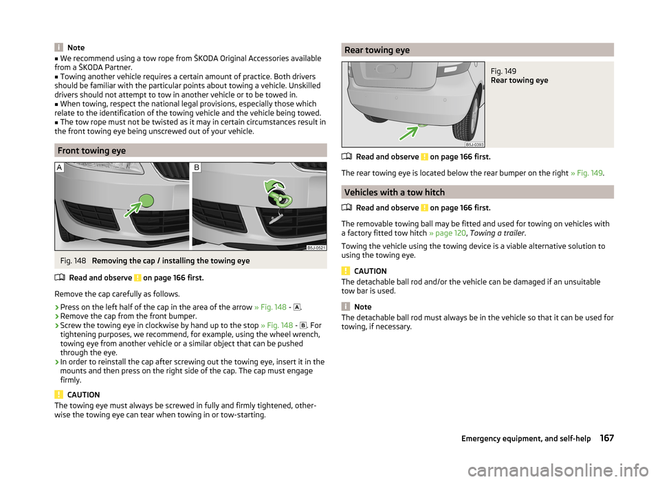
Fig. 148
Removing the cap / installing the towing eye
Read and observe
on page 166 first.
Remove the cap carefully as follows.
›
Press on the left half of the cap in the area of the arrow » Fig. 148 -
.
›
Remove the cap from the front bumper.
›
Screw the towing eye in clockwise by hand up to the stop
» Fig. 148 -
. For
tightening purposes, we recommend, for example, using the wheel wrench,
towing eye from another vehicle or a similar object that can be pushed
through the eye.
›
In order to reinstall the cap after screwing out the towing eye, insert it in the
mounts and then press on the right side of the cap. The cap must engage
firmly.
CAUTION
The towing eye must always be screwed in fully and firmly tightened, other-
wise the towing eye can tear when towing in or tow-starting.Rear towing eyeFig. 149
Rear towing eye
Read and observe on page 166 first.
The rear towing eye is located below the rear bumper on the right » Fig. 149.
Vehicles with a tow hitch
Read and observe
on page 166 first.
The removable towing ball may be fitted and used for towing on vehicles with
a factory fitted tow hitch » page 120, Towing a trailer .
Towing the vehicle using the towing device is a viable alternative solution to
using the towing eye.
CAUTION
The detachable ball rod and/or the vehicle can be damaged if an unsuitable
tow bar is used.
Note
The detachable ball rod must always be in the vehicle so that it can be used for
towing, if necessary.167Emergency equipment, and self-help
Page 178 of 197
Technical data
Technical data
Vehicle data
Introduction
This chapter contains information on the following subjects:
Vehicle identification data
176
Operating weight and payload
176
measurement of fuel consumption and CO 2 emissions according to ECE
Regulations and EU Directives
177
Dimensions
178
Vehicle-specific details according to engine type
179
The details given in the vehicle's technical documentation always take prece-
dence over the details in the Owner's Manual.
The listed performance values were determined without performance-reduc- ing equipment, e.g. air conditioning system.
Vehicle identification data
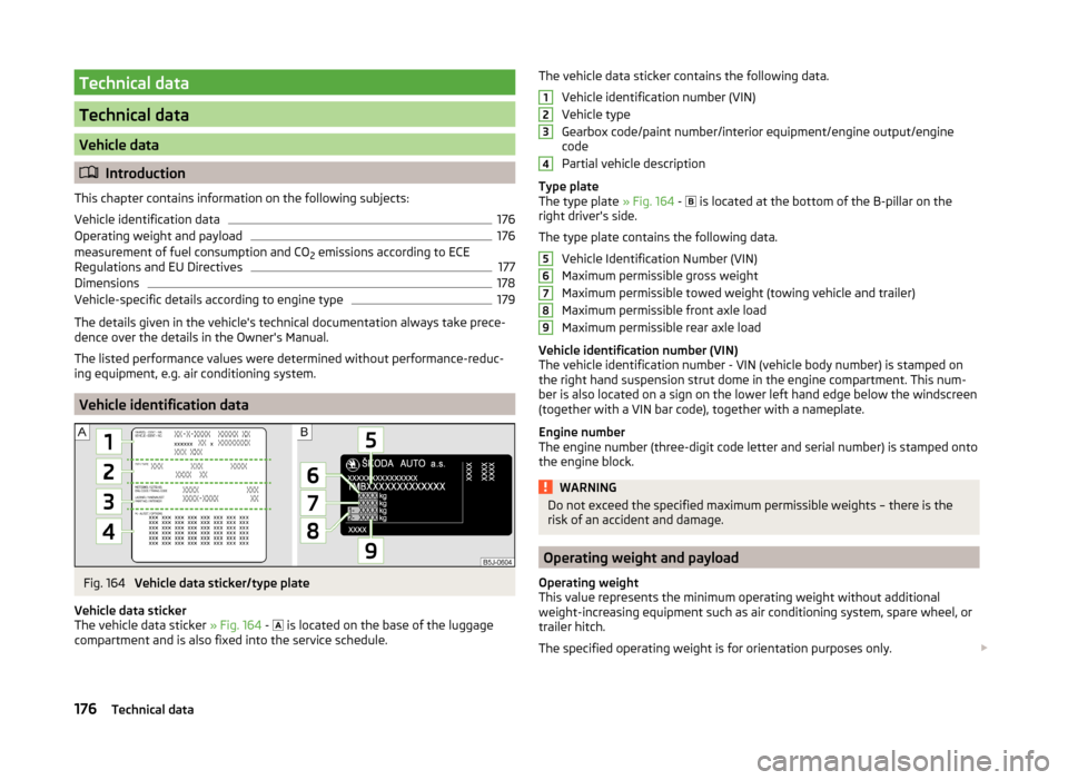
Fig. 164
Vehicle data sticker/type plate
Vehicle data sticker
The vehicle data sticker » Fig. 164 -
is located on the base of the luggage
compartment and is also fixed into the service schedule.
The vehicle data sticker contains the following data.
Vehicle identification number (VIN)
Vehicle type
Gearbox code/paint number/interior equipment/engine output/engine
code
Partial vehicle description
Type plate
The type plate » Fig. 164 -
is located at the bottom of the B-pillar on the
right driver's side.
The type plate contains the following data. Vehicle Identification Number (VIN)
Maximum permissible gross weight
Maximum permissible towed weight (towing vehicle and trailer)
Maximum permissible front axle load
Maximum permissible rear axle load
Vehicle identification number (VIN)
The vehicle identification number - VIN (vehicle body number) is stamped on
the right hand suspension strut dome in the engine compartment. This num-
ber is also located on a sign on the lower left hand edge below the windscreen
(together with a VIN bar code), together with a nameplate.
Engine number
The engine number (three-digit code letter and serial number) is stamped onto
the engine block.WARNINGDo not exceed the specified maximum permissible weights – there is the
risk of an accident and damage.
Operating weight and payload
Operating weight
This value represents the minimum operating weight without additional
weight-increasing equipment such as air conditioning system, spare wheel, or
trailer hitch.
The specified operating weight is for orientation purposes only.
123456789176Technical data