ECU SKODA FABIA 2014 3.G / NJ Operating Instruction Manual
[x] Cancel search | Manufacturer: SKODA, Model Year: 2014, Model line: FABIA, Model: SKODA FABIA 2014 3.G / NJPages: 216, PDF Size: 30.9 MB
Page 91 of 216
Downloaded from www.Manualslib.com manuals search engine Cargo elementFig. 95
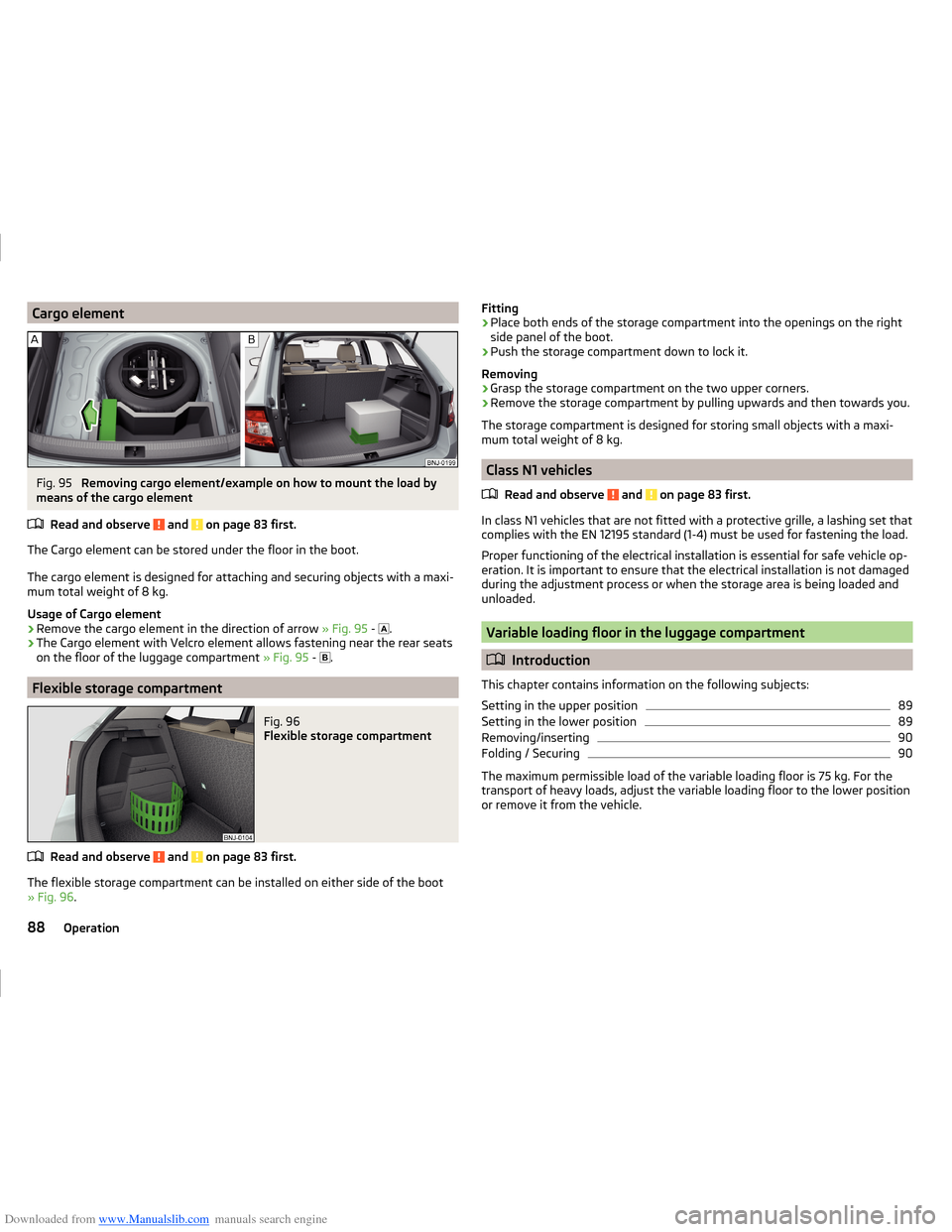
Removing cargo element/example on how to mount the load by
means of the cargo element
Read and observe
and on page 83 first.
The Cargo element can be stored under the floor in the boot.
The cargo element is designed for attaching and securing objects with a maxi-
mum total weight of 8 kg.
Usage of Cargo element
›
Remove the cargo element in the direction of arrow » Fig. 95 -
.
›
The Cargo element with Velcro element allows fastening near the rear seats
on the floor of the luggage compartment » Fig. 95 -
.
Flexible storage compartment
Fig. 96
Flexible storage compartment
Read and observe and on page 83 first.
The flexible storage compartment can be installed on either side of the boot
» Fig. 96 .
Fitting›Place both ends of the storage compartment into the openings on the right
side panel of the boot.›
Push the storage compartment down to lock it.
Removing
›
Grasp the storage compartment on the two upper corners.
›
Remove the storage compartment by pulling upwards and then towards you.
The storage compartment is designed for storing small objects with a maxi-
mum total weight of 8 kg.
Class N1 vehicles
Read and observe
and on page 83 first.
In class N1 vehicles that are not fitted with a protective grille, a lashing set that
complies with the EN 12195 standard (1-4) must be used for fastening the load.
Proper functioning of the electrical installation is essential for safe vehicle op-
eration. It is important to ensure that the electrical installation is not damaged
during the adjustment process or when the storage area is being loaded and
unloaded.
Variable loading floor in the luggage compartment
Introduction
This chapter contains information on the following subjects:
Setting in the upper position
89
Setting in the lower position
89
Removing/inserting
90
Folding / Securing
90
The maximum permissible load of the variable loading floor is 75 kg. For the
transport of heavy loads, adjust the variable loading floor to the lower position
or remove it from the vehicle.
88Operation
Page 93 of 216
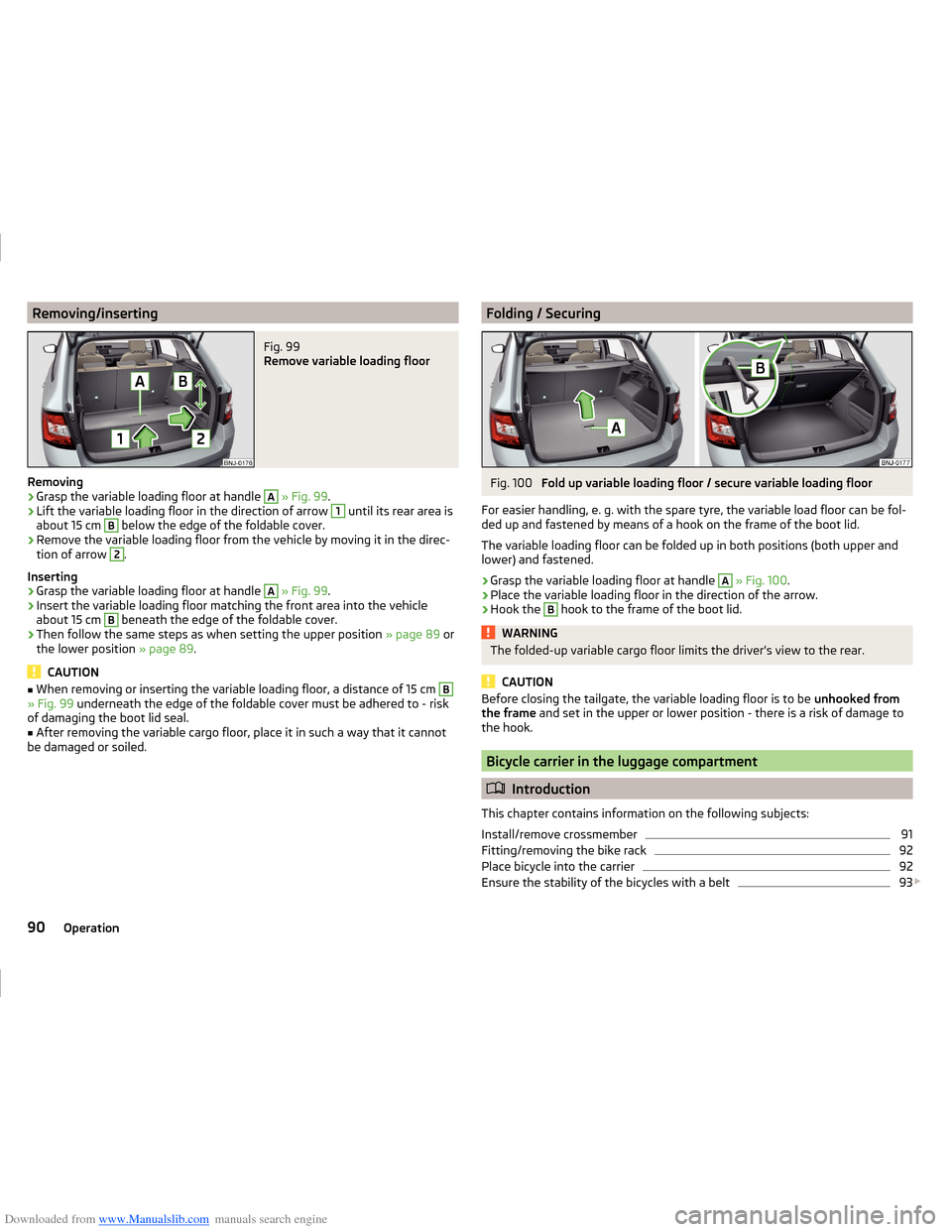
Downloaded from www.Manualslib.com manuals search engine Removing/insertingFig. 99
Remove variable loading floor
Removing
›
Grasp the variable loading floor at handle
A
» Fig. 99 .
›
Lift the variable loading floor in the direction of arrow
1
until its rear area is
about 15 cm
B
below the edge of the foldable cover.
›
Remove the variable loading floor from the vehicle by moving it in the direc-
tion of arrow
2
.
Inserting
›
Grasp the variable loading floor at handle
A
» Fig. 99 .
›
Insert the variable loading floor matching the front area into the vehicle
about 15 cm
B
beneath the edge of the foldable cover.
›
Then follow the same steps as when setting the upper position » page 89 or
the lower position » page 89.
CAUTION
■
When removing or inserting the variable loading floor, a distance of 15 cm B» Fig. 99 underneath the edge of the foldable cover must be adhered to - risk
of damaging the boot lid seal.■
After removing the variable cargo floor, place it in such a way that it cannot
be damaged or soiled.
Folding / SecuringFig. 100
Fold up variable loading floor / secure variable loading floor
For easier handling, e. g. with the spare tyre, the variable load floor can be fol-
ded up and fastened by means of a hook on the frame of the boot lid.
The variable loading floor can be folded up in both positions (both upper and
lower) and fastened.
›
Grasp the variable loading floor at handle
A
» Fig. 100 .
›
Place the variable loading floor in the direction of the arrow.
›
Hook the
B
hook to the frame of the boot lid.
WARNINGThe folded-up variable cargo floor limits the driver's view to the rear.
CAUTION
Before closing the tailgate, the variable loading floor is to be unhooked from
the frame and set in the upper or lower position - there is a risk of damage to
the hook.
Bicycle carrier in the luggage compartment
Introduction
This chapter contains information on the following subjects:
Install/remove crossmember
91
Fitting/removing the bike rack
92
Place bicycle into the carrier
92
Ensure the stability of the bicycles with a belt
93
90Operation
Page 95 of 216
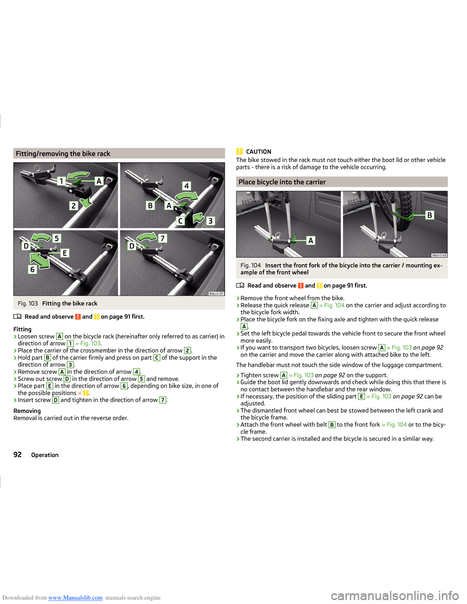
Downloaded from www.Manualslib.com manuals search engine Fitting/removing the bike rackFig. 103
Fitting the bike rack
Read and observe
and on page 91 first.
Fitting
›
Loosen screw
A
on the bicycle rack (hereinafter only referred to as carrier) in
direction of arrow
1
» Fig. 103 .
›
Place the carrier of the crossmember in the direction of arrow
2
.
›
Hold part
B
of the carrier firmly and press on part
C
of the support in the
direction of arrow
3
.
›
Remove screw
A
in the direction of arrow
4
.
›
Screw out screw
D
in the direction of arrow
5
and remove.
›
Place part
E
in the direction of arrow
6
, depending on bike size, in one of
the possible positions » .
›
Insert screw
D
and tighten in the direction of arrow
7
.
Removing
Removal is carried out in the reverse order.
CAUTIONThe bike stowed in the rack must not touch either the boot lid or other vehicle
parts - there is a risk of damage to the vehicle occurring.
Place bicycle into the carrier
Fig. 104
Insert the front fork of the bicycle into the carrier / mounting ex-
ample of the front wheel
Read and observe
and on page 91 first.
›
Remove the front wheel from the bike.
›
Release the quick release
A
» Fig. 104 on the carrier and adjust according to
the bicycle fork width.
›
Place the bicycle fork on the fixing axle and tighten with the quick release
A
.
›
Set the left bicycle pedal towards the vehicle front to secure the front wheel
more easily.
›
If you want to transport two bicycles, loosen screw
A
» Fig. 103 on page 92
on the carrier and move the carrier along with attached bike to the left.
The handlebar must not touch the side window of the luggage compartment.
›
Tighten screw
A
» Fig. 103 on page 92 on the support.
›
Guide the boot lid gently downwards and check while doing this that there is
no contact between the handlebar and the rear window.
›
If necessary, the position of the sliding part
E
» Fig. 103 on page 92 can be
adjusted.
›
The dismantled front wheel can best be stowed between the left crank and
the bicycle frame.
›
Attach the front wheel with belt
B
to the front fork » Fig. 104 or to the bicy-
cle frame.
›
The second carrier is installed and the bicycle is secured in a similar way.
92Operation
Page 96 of 216
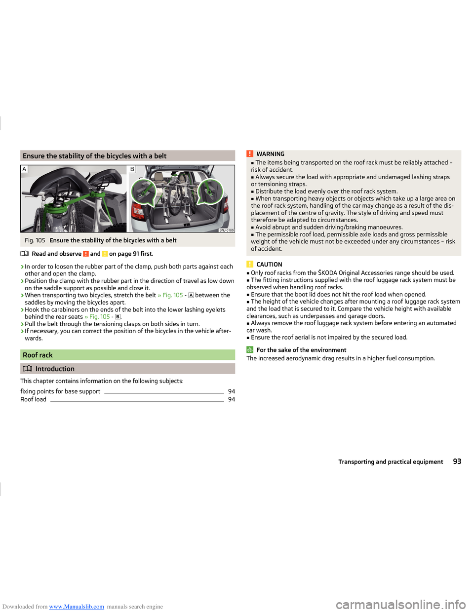
Downloaded from www.Manualslib.com manuals search engine Ensure the stability of the bicycles with a beltFig. 105
Ensure the stability of the bicycles with a belt
Read and observe
and on page 91 first.
›
In order to loosen the rubber part of the clamp, push both parts against each
other and open the clamp.
›
Position the clamp with the rubber part in the direction of travel as low down
on the saddle support as possible and close it.
›
When transporting two bicycles, stretch the belt » Fig. 105 -
between the
saddles by moving the bicycles apart.
›
Hook the carabiners on the ends of the belt into the lower lashing eyelets
behind the rear seats » Fig. 105 -
.
›
Pull the belt through the tensioning clasps on both sides in turn.
›
If necessary, you can correct the position of the bicycles in the vehicle after-
wards.
Roof rack
Introduction
This chapter contains information on the following subjects:
fixing points for base support
94
Roof load
94WARNING■ The items being transported on the roof rack must be reliably attached –
risk of accident.■
Always secure the load with appropriate and undamaged lashing straps
or tensioning straps.
■
Distribute the load evenly over the roof rack system.
■
When transporting heavy objects or objects which take up a large area on
the roof rack system, handling of the car may change as a result of the dis-
placement of the centre of gravity. The style of driving and speed must
therefore be adapted to circumstances.
■
Avoid abrupt and sudden driving/braking manoeuvres.
■
The permissible roof load, permissible axle loads and gross permissible
weight of the vehicle must not be exceeded under any circumstances – risk
of accident.
CAUTION
■ Only roof racks from the ŠKODA Original Accessories range should be used.■The fitting instructions supplied with the roof luggage rack system must be
observed when handling roof racks.■
Ensure that the boot lid does not hit the roof load when opened.
■
The height of the vehicle changes after mounting a roof luggage rack system
and the load that is secured to it. Compare the vehicle height with available
clearances, such as underpasses and garage doors.
■
Always remove the roof luggage rack system before entering an automated
car wash.
■
Ensure the roof aerial is not impaired by the secured load.
For the sake of the environment
The increased aerodynamic drag results in a higher fuel consumption.93Transporting and practical equipment
Page 110 of 216
Downloaded from www.Manualslib.com manuals search engine WARNINGOnly apply the brakes for the purpose of drying and cleaning the brake
discs if the traffic conditions permit this. Do not place any other road users
in jeopardy.
Handbrake
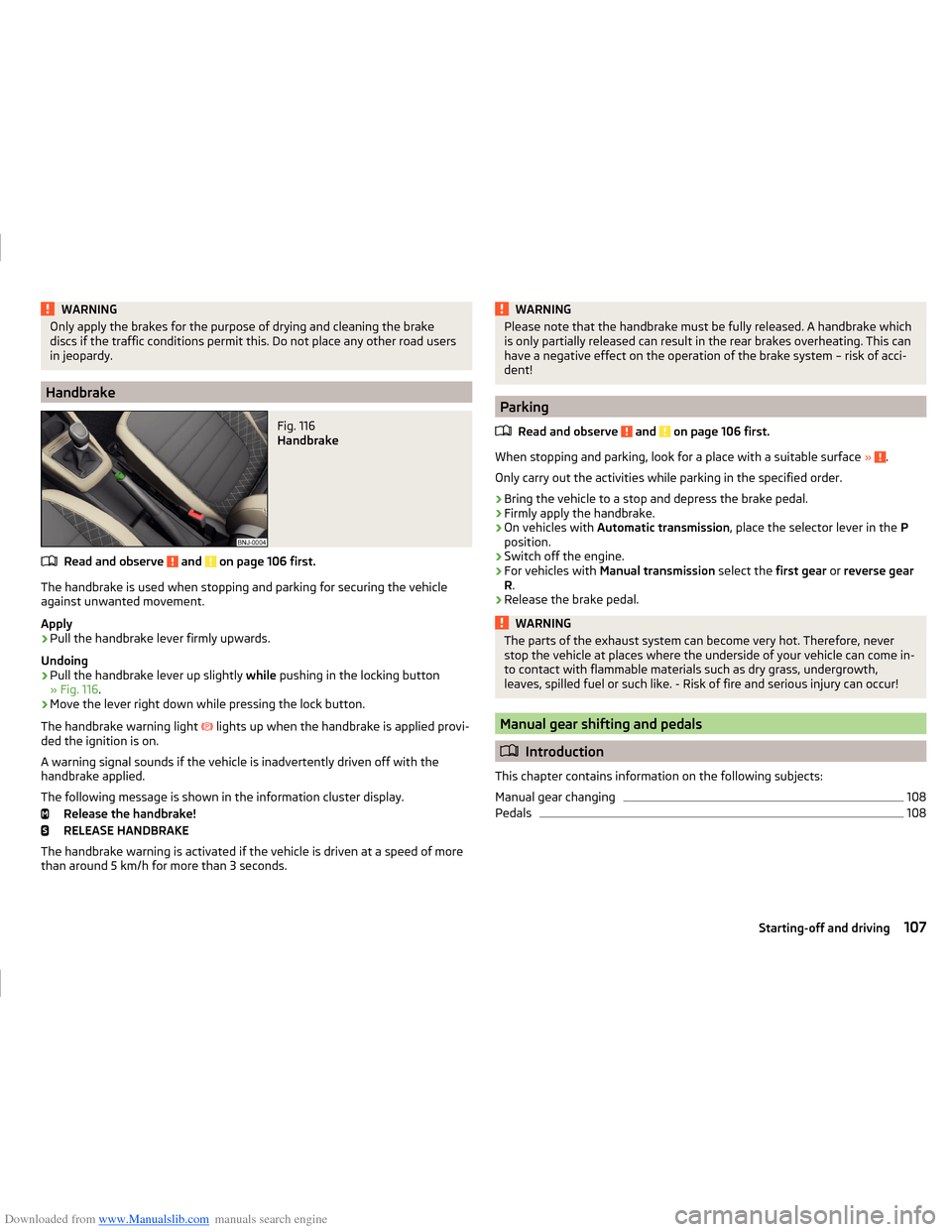
Fig. 116
Handbrake
Read and observe and on page 106 first.
The handbrake is used when stopping and parking for securing the vehicle
against unwanted movement.
Apply
›
Pull the handbrake lever firmly upwards.
Undoing
›
Pull the handbrake lever up slightly while pushing in the locking button
» Fig. 116 .
›
Move the lever right down while pressing the lock button.
The handbrake warning light
lights up when the handbrake is applied provi-
ded the ignition is on.
A warning signal sounds if the vehicle is inadvertently driven off with the
handbrake applied.
The following message is shown in the information cluster display. Release the handbrake!
RELEASE HANDBRAKE
The handbrake warning is activated if the vehicle is driven at a speed of more
than around 5 km/h for more than 3 seconds.
WARNINGPlease note that the handbrake must be fully released. A handbrake which
is only partially released can result in the rear brakes overheating. This can
have a negative effect on the operation of the brake system – risk of acci-
dent!
Parking
Read and observe
and on page 106 first.
When stopping and parking, look for a place with a suitable surface » .
Only carry out the activities while parking in the specified order.
›
Bring the vehicle to a stop and depress the brake pedal.
›
Firmly apply the handbrake.
›
On vehicles with Automatic transmission , place the selector lever in the P
position.
›
Switch off the engine.
›
For vehicles with Manual transmission select the first gear or reverse gear
R .
›
Release the brake pedal.
WARNINGThe parts of the exhaust system can become very hot. Therefore, never
stop the vehicle at places where the underside of your vehicle can come in-
to contact with flammable materials such as dry grass, undergrowth,
leaves, spilled fuel or such like. - Risk of fire and serious injury can occur!
Manual gear shifting and pedals
Introduction
This chapter contains information on the following subjects:
Manual gear changing
108
Pedals
108107Starting-off and driving
Page 130 of 216
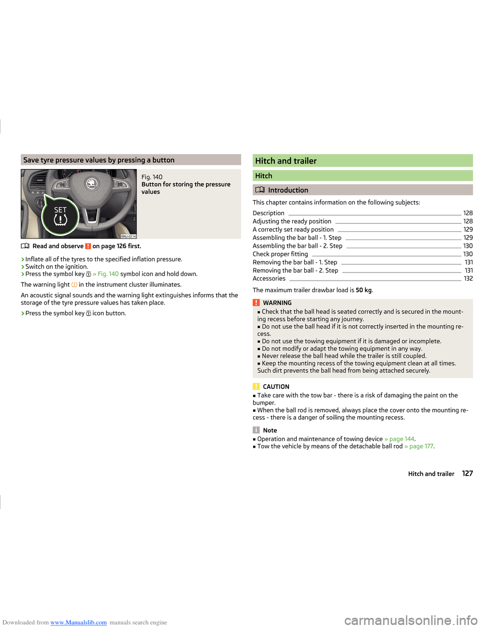
Downloaded from www.Manualslib.com manuals search engine Save tyre pressure values by pressing a buttonFig. 140
Button for storing the pressure
values
Read and observe on page 126 first.
›
Inflate all of the tyres to the specified inflation pressure.
›
Switch on the ignition.
›
Press the symbol key
» Fig. 140 symbol icon and hold down.
The warning light in the instrument cluster illuminates.
An acoustic signal sounds and the warning light extinguishes informs that the
storage of the tyre pressure values has taken place.
›
Press the symbol key icon button.
Hitch and trailer
Hitch
Introduction
This chapter contains information on the following subjects:
Description
128
Adjusting the ready position
128
A correctly set ready position
129
Assembling the bar ball - 1. Step
129
Assembling the bar ball - 2. Step
130
Check proper fitting
130
Removing the bar ball - 1. Step
131
Removing the bar ball - 2. Step
131
Accessories
132
The maximum trailer drawbar load is 50 kg.
WARNING■
Check that the ball head is seated correctly and is secured in the mount-
ing recess before starting any journey.■
Do not use the ball head if it is not correctly inserted in the mounting re-
cess.
■
Do not use the towing equipment if it is damaged or incomplete.
■
Do not modify or adapt the towing equipment in any way.
■
Never release the ball head while the trailer is still coupled.
■
Keep the mounting recess of the towing equipment clean at all times.
Such dirt prevents the ball head from being attached securely.
CAUTION
■ Take care with the tow bar - there is a risk of damaging the paint on the
bumper.■
When the ball rod is removed, always place the cover onto the mounting re-
cess - there is a danger of soiling the mounting recess.
Note
■ Operation and maintenance of towing device » page 144.■Tow the vehicle by means of the detachable ball rod » page 177.127Hitch and trailer
Page 133 of 216
Downloaded from www.Manualslib.com manuals search engine The operating lever C automatically turns upwards in the direction of arrow4 and the release pin D pops out (both its red and green parts are visible)
» .
If the operating lever
C
does not turn automatically, or if the release pin
D
does not pop out, remove the tow bar from the mounting recess by turning the
operating lever
C
downwards as far as it can go. Clean the contact surfaces
on the tow bar and the mounting recess.
WARNING■ Carefully remove the cap for the mounting recess B - there is a risk of
hand injury.■
Keep your hands outside the operating lever's range of motion when at-
taching the ball head – there is a risk of finger injury.
■
Never attempt to pull the operating lever upwards forcibly to turn the
key. Doing so would mean the ball head is not attached correctly.
CAUTION
Remove the cover A from the rear bumper with care - there is a risk of paint
damage to the bumper and the cap.
Note
Store the caps A and B » Fig. 145 in a suitable place in the luggage compart-
ment after removal.
Assembling the bar ball - 2. Step
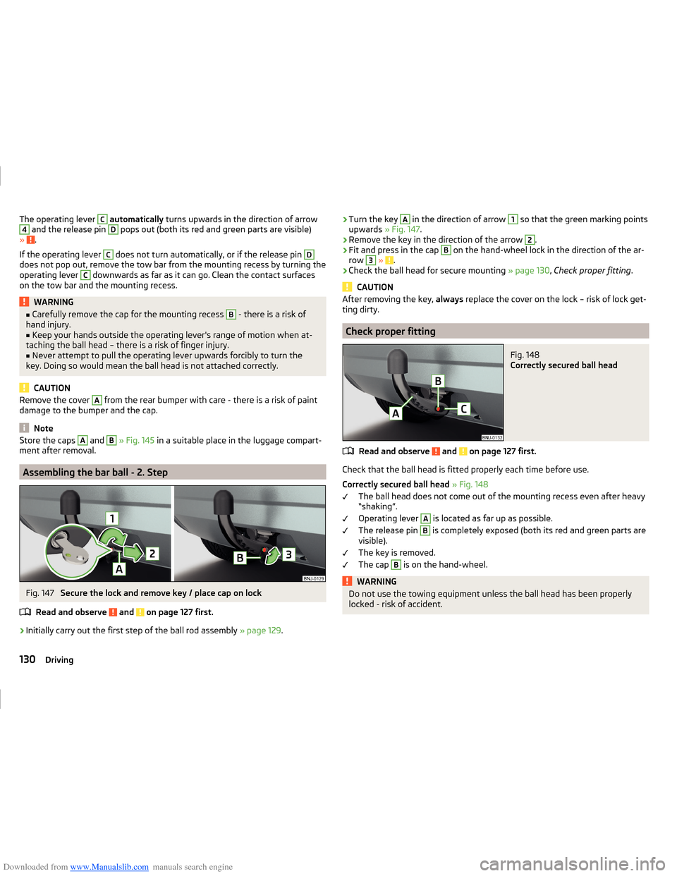
Fig. 147
Secure the lock and remove key / place cap on lock
Read and observe
and on page 127 first.
›
Initially carry out the first step of the ball rod assembly » page 129.
›Turn the key A in the direction of arrow 1 so that the green marking points
upwards » Fig. 147.›
Remove the key in the direction of the arrow
2
.
›
Fit and press in the cap
B
on the hand-wheel lock in the direction of the ar-
row
3
» .
›
Check the ball head for secure mounting » page 130, Check proper fitting .
CAUTION
After removing the key, always replace the cover on the lock – risk of lock get-
ting dirty.
Check proper fitting
Fig. 148
Correctly secured ball head
Read and observe and on page 127 first.
Check that the ball head is fitted properly each time before use.
Correctly secured ball head » Fig. 148
The ball head does not come out of the mounting recess even after heavy
“shaking”.
Operating lever
A
is located as far up as possible.
The release pin
B
is completely exposed (both its red and green parts are
visible).
The key is removed.
The cap
B
is on the hand-wheel.
WARNINGDo not use the towing equipment unless the ball head has been properly
locked - risk of accident.130Driving
Page 134 of 216
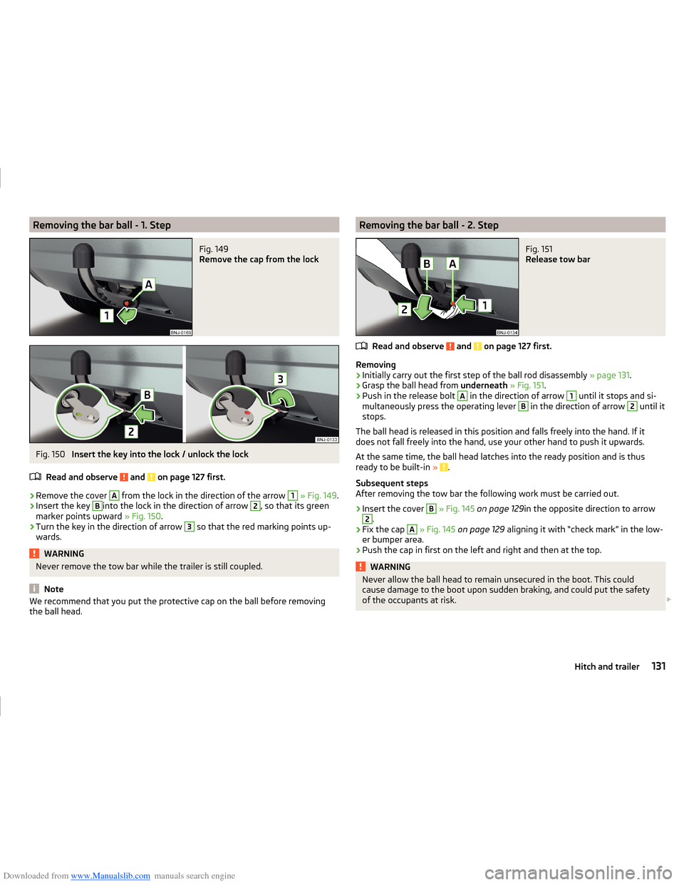
Downloaded from www.Manualslib.com manuals search engine Removing the bar ball - 1. StepFig. 149
Remove the cap from the lock
Fig. 150
Insert the key into the lock / unlock the lock
Read and observe
and on page 127 first.
›
Remove the cover
A
from the lock in the direction of the arrow
1
» Fig. 149 .
›
Insert the key
B
into the lock in the direction of arrow
2
, so that its green
marker points upward » Fig. 150.
›
Turn the key in the direction of arrow
3
so that the red marking points up-
wards.
WARNINGNever remove the tow bar while the trailer is still coupled.
Note
We recommend that you put the protective cap on the ball before removing
the ball head.Removing the bar ball - 2. StepFig. 151
Release tow bar
Read and observe and on page 127 first.
Removing
›
Initially carry out the first step of the ball rod disassembly » page 131.
›
Grasp the ball head from underneath » Fig. 151 .
›
Push in the release bolt
A
in the direction of arrow
1
until it stops and si-
multaneously press the operating lever
B
in the direction of arrow
2
until it
stops.
The ball head is released in this position and falls freely into the hand. If it
does not fall freely into the hand, use your other hand to push it upwards.
At the same time, the ball head latches into the ready position and is thus
ready to be built-in »
.
Subsequent steps
After removing the tow bar the following work must be carried out.
›
Insert the cover
B
» Fig. 145 on page 129 in the opposite direction to arrow
2
.
›
Fix the cap
A
» Fig. 145 on page 129 aligning it with “check mark” in the low-
er bumper area.
›
Push the cap in first on the left and right and then at the top.
WARNINGNever allow the ball head to remain unsecured in the boot. This could
cause damage to the boot upon sudden braking, and could put the safety
of the occupants at risk. 131Hitch and trailer
Page 136 of 216
Downloaded from www.Manualslib.com manuals search engine Trailer, connect and disconnectFig. 153
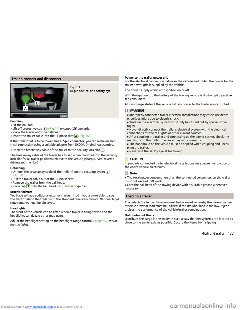
13-pin socket, and safety eye
Coupling
›
Fit the ball rod.
›
Lift off protective cap
3
» Fig. 141 on page 128 upwards.
›
Place the trailer onto the ball head.
›
Insert the trailer cable into the 13-pin socket
A
» Fig. 153.
If the trailer that is to be towed has a 7-pin connector, you can make an elec-
trical connection using a suitable adapter from ŠKODA Original Accessories.
›
Hook the breakaway cable of the trailer to the security lock slot
B
.
The breakaway cable of the trailer has to sag when mounted into the security
lock slot for all trailer positions relative to the vehicle (sharp curves, reverse
driving and the like.)
Detaching
›
Unhook the breakaway cable of the trailer from the securing eyelet
B
» Fig. 153 .
›
Pull the trailer cable out of the 13-pin socket.
›
Remove the trailer from the ball head.
›
Place cap
3
onto the ball head » Fig. 141 on page 128 .
Exterior mirrors
You have to have additional exterior mirrors fitted if you are not able to see
the traffic behind the trailer with the standard rear-view mirrors. National legal
requirements must be observed.
Headlights
The front of the vehicle can be lifted when a trailer is being towed and the
headlights can dazzle other road users.
Adjust the headlight setting on the headlight range control » page 60, Operat-
ing the lights .
Power to the trailer power grid
For the electrical connection between the vehicle and trailer, the power for the
trailer power grid is supplied by the vehicle.
The power supply works with ignition on or off.
With the ignition off, the battery of the towing vehicle is discharged by activa-
ted consumers.
At low charge state of the vehicle battery power to the trailer is interrupted.WARNING■ Improperly connected trailer electrical installations may cause accidents
or serious injury due to electric shock.■
Work on the electrical system must only be carried out by specialist ga-
rages.
■
Never directly connect the trailer's electrical system with the electrical
connections for the tail lights or other current sources.
■
After coupling the trailer and connecting up the power socket, check the
rear lights on the trailer to ensure they work correctly.
■
The handbrake on the vehicle must be applied when coupling and uncou-
pling the trailer.
■
Never use the safety eyelet for towing!
CAUTION
Improperly connected trailer electrical installations may cause malfunction of
the entire vehicle electronics.
Note
■ The total power consumption of all the connected consumers on the trailer
must not exceed 350 watts.■
Coat the ball head of the towing device with a suitable grease whenever
necessary.
Loading a trailer
The vehicle/trailer combination must be balanced, whereby the maximum per-
missible drawbar load must be utilised. If the drawbar load is too low, it jeop-
ardises the performance of the vehicle/trailer combination.
Distribution of the cargo
Distribute the cargo in the trailer in such a way that heavy items are located as
close to the trailer axle as possible. Secure the items from slipping.
133Hitch and trailer
Page 137 of 216
Downloaded from www.Manualslib.com manuals search engine The distribution of the weight is very poor if your vehicle is unladen and the
trailer is laden. Maintain a particularly low speed if you cannot avoid driving
with this combination.
Tyre pressure
Correct the tyre inflation pressure on your vehicle for a “full load” » page 161.
Towing capacity and trailer weight
The permissible trailer load must not be exceeded under any circumstances
» page 192 , Technical data .
The details given in the vehicle's technical documentation always take prece-
dence over the details in the Owner's Manual.
The trailer loads specified apply only to altitudes up to 1,000 metres above
mean sea level.
The engine output falls as altitude increases, as does the ability to climb.
Therefore, for every additional 1,000 m in height (or part), the maximum per-
missible towed weight must be reduced by 10 %.
The towed weight comprises the actual weights of the (loaded) towing vehicle and the (loaded) trailer.
The trailer and drawbar load information on the type plate of the towing
equipment are merely test data for the towing equipment. The vehicle-specific
values are detailed in the vehicle documents.WARNING■ Do not exceed the maximum permissible axle and drawbar load and
weight of the trailer - risk of accident and serious injuries!■
An unsecured load can adversely affect stability and driving safety signifi-
cantly - there is a risk of accident!
Towing a trailer
Driving speed
For safety reasons, do not drive faster than 80 km/h when towing a trailer.
Immediately reduce your speed as soon as even the slightest swaying of the
trailer is detected. Never attempt to stop the trailer from “swaying” by acceler-
ating.
Brakes
Apply the brakes in good time! If the trailer is fitted with a trailer brake, apply
the brakes gently at first, then brake firmly. This will avoid brake jolts resulting
from the trailer wheels locking.
On downhill sections shift down a gear in good time to also use the engine as
a brake.
Engine overheating
If the pointer of the coolant temperature gauge reaches the red scale range,
the speed should be reduced immediately.
Stop and switch off the engine if the warning light
illuminates in the instru-
ment cluster display.
The following information must be observed » page 36,
Coolant
.
The coolant temperature can be reduced by switching on the heating.WARNING■ Always drive particularly carefully with the trailer.■Adapt your speed to the conditions of the road surface and to the traffic
situation.
CAUTION
If you tow a trailer frequently, you should also have your vehicle inspected be-
tween service intervals.
Anti-theft alarm system
When the vehicle is locked, the alarm is activated when the electrical connec-
tion to the trailer is interrupted.
Always switch off the anti-theft alarm system before a trailer is coupled or un-
coupled » page 54 .
Conditions for including a trailer in the anti-theft alarm system. The vehicle is factory-fitted with an anti-theft alarm system and towing
equipment.
The trailer is electrically connected to the towing vehicle by means of the
trailer socket.
The electrical system of the vehicle and trailer is functional.
The vehicle is locked with the vehicle key and the anti-theft alarm system
is activated.
134Driving