ECU SKODA FABIA 2014 3.G / NJ Operating Instruction Manual
[x] Cancel search | Manufacturer: SKODA, Model Year: 2014, Model line: FABIA, Model: SKODA FABIA 2014 3.G / NJPages: 216, PDF Size: 30.9 MB
Page 152 of 216
Downloaded from www.Manualslib.com manuals search engine CAUTIONDo not use fuels with metal components, such as LRP (lead replacement
petrol) may be used. Risk of causing considerable damage to parts of the en-
gine or exhaust system.
Note
■ Unleaded petrol that has a higher octane number than that required by the
engine can be used without limitations.■
The use of petrol with an octane rating higher than 95 RON in does not re-
sult in either a noticeable increase in power nor lower fuel consumption in ve-
hicles for which unleaded petrol 95/91, 92 or 93 RON is specified.
■
On vehicles using prescribed unleaded petrol of min. 95 RON, the use of pet-
rol with a higher octane number than 95 RON can increase the power and re-
duce fuel consumption.
Diesel fuel
The correct fuel grades for your vehicle are specified on the inside of the fuel
filler flap.
Read and observe
on page 147 first.
The vehicle can only be operated with diesel fuel that meets the EN 5901)
standard.
All diesel engines can be operated using diesel fuel with a maximum of 7% bi-
odiesel (B7)2)
.
On the Indian market, your vehicle will only be able to run on diesel fuel com-
pliant with standard IS 1460/Bharat IV. If diesel fuel which complies with this
standard is not available, you can refuel with diesel fuel according to standard
IS 1460/Bharat III in case of emergency.
Operation in winter - winter-grade diesel fuel
In the cold season, only use “winter-grade diesel fuel” which will still operate properly even at a temperature of -20 °C.
It is often the case in countries with different climatic conditions that diesel
fuels available have a different temperature characteristic. ŠKODA Partners
and filling stations in the relevant country will be able to provide you with in-
formation regarding the diesel fuels available.
Preheating fuel
The vehicle is fitted with a fuel filter preheating system. This secures opera- tion of a vehicle using diesel fuel down to an environmental temperature of
-24 °C.
Diesel fuel additives
The diesel fuel in accordance with the prescribed standards meets all the con-
ditions for a smooth running engine. We therefore recommend that no diesel
fuel additives are used. This can result in considerable damage to parts of the
engine or the exhaust system.
CAUTION
■ Just filling the tank once with diesel fuel that does not comply with the
standard, can cause severe damage to parts of the engine, the fuel and ex-
haust system.■
If a different fuel other than diesel fuel, which complies to the above men-
tioned standards (e.g. petrol) is used, do not start the engine or switch on the
ignition! Extensive damage to engine parts can occur.
■
Water which has collected in the fuel filter can cause engine faults.
CAUTION
■ The vehicle cannot be operated with biofuel RME, therefore this fuel must
not be filled in the tank and used for driving the vehicle. The use of biofuel
RME can cause considerable damage to parts of the engine or fuel system.■
Do not mix any fuel additives, so-called “flow improvers” (petrol and similar
agents), into the diesel. This can result in considerable damage to parts of the
engine or the exhaust system.
Engine compartment
Introduction
This chapter contains information on the following subjects:
Opening and closing the bonnet
151
Engine compartment overview
151
Radiator fan
152
Windscreen washer system
152
1)
In Germany also DIN 51628, in Austria ÖNORM C 1590, in Russia GOST R 52368-2005 / EN 590:2004.
2)
In Germany complying with standard DIN 52638, in Austria ÖNORM C 1590, in France EN 590.
149Inspecting and replenishing
Page 153 of 216
Downloaded from www.Manualslib.com manuals search engine WARNINGWhen working in the engine compartment, injuries, scalding, accident or
fire hazards may arise. For this reason, it is essential to comply with the
warning instructions stated below and with the generally applicable rules
of safety. The engine compartment of your car is a hazardous area.WARNINGInstructions before beginning work in the engine compartment■Turn off the engine and remove the ignition key.■
Firmly apply the handbrake.
■
For vehicles with manual transmission the lever into the neutral position.
■
On vehicles with automatic transmission, shift the selector lever into the
P position.
■
Allow the engine to cool.
■
Never open the bonnet if you can see steam or coolant flowing out of the
engine compartment – there is a risk of scalding. Wait until the steam or
coolant has stopped escaping.
WARNINGInformation for working in the engine room■Keep all people, especially children, away from the engine compartment.■
Never touch the radiator fan while the engine is still warm. The fan might
suddenly start running!
■
Do not touch any hot engine parts – there is a risk of burns.
WARNINGInformation for working in the engine compartment with the engine run-
ning■
Pay particular attention to moving engine parts, e.g. V-ribbed belt, gener-
ator, radiator fan - danger to life!
■
Never touch the electric wiring on the ignition system.
■
Avoid short circuits in the electrical system, particularly on the vehicle's
battery.
■
Always make sure that no jewellery, loose clothing or long hair can get
caught in rotating engine parts – there is a risk of death. Always remove
any jewellery, tie back long hair and wear tight fitting clothing before com-
pleting any work.
WARNINGInformation for working on the fuel system or the electrical system■Always disconnect the vehicle battery from the electrical system.■
Do not smoke.
■
Never work near open flames.
■
Always have a functioning fire extinguisher nearby.
WARNING■ Read the information and warning instructions on the fluid containers.■Keep the working fluids in sealed original containers and safe from peo-
ple who are not completely independent, e.g. children.■
Never spill operating fluids over the hot engine - risk of fire.
■
If you wish to work under the vehicle, you must secure the vehicle against
rolling away and support it with suitable axle stands: the car jack is not suf-
ficient for this – there is a risk of injury.
CAUTION
Always top up using the correct specification of fluids. This may result in major
operating problems and also vehicle damage!
For the sake of the environment
In view of the requirements for the environmentally friendly disposal of fluids and the special tools and knowledge required for such work, we recommend
that fluids be changed by a specialist garage.
Note
■ If there is anything you are not sure about concerning fluids, please consult a
specialist garage.■
Fluids with the proper specifications can be purchased from the ŠKODA Origi-
nal Accessories or from the ŠKODA Genuine Parts ranges.
150General Maintenance
Page 154 of 216
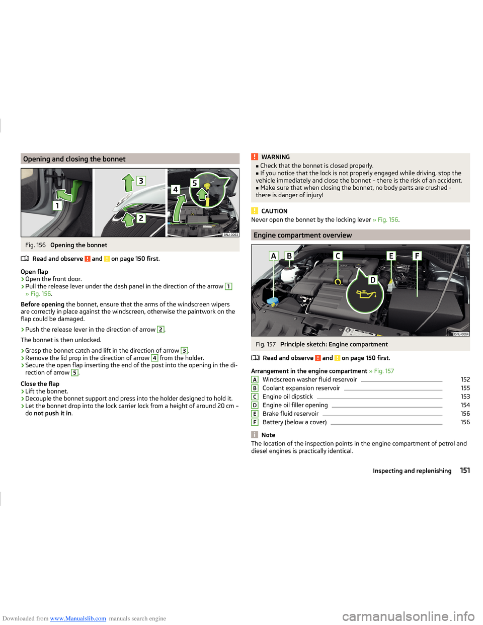
Downloaded from www.Manualslib.com manuals search engine Opening and closing the bonnetFig. 156
Opening the bonnet
Read and observe
and on page 150 first.
Open flap
›
Open the front door.
›
Pull the release lever under the dash panel in the direction of the arrow
1
» Fig. 156 .
Before opening the bonnet, ensure that the arms of the windscreen wipers
are correctly in place against the windscreen, otherwise the paintwork on the
flap could be damaged.
›
Push the release lever in the direction of arrow
2
.
The bonnet is then unlocked.
›
Grasp the bonnet catch and lift in the direction of arrow
3
.
›
Remove the lid prop in the direction of arrow
4
from the holder.
›
Secure the open flap inserting the end of the post into the opening in the di-
rection of arrow
5
.
Close the flap
›
Lift the bonnet.
›
Decouple the bonnet support and press into the holder designed to hold it.
›
Let the bonnet drop into the lock carrier lock from a height of around 20 cm –
do not push it in .
WARNING■
Check that the bonnet is closed properly.■If you notice that the lock is not properly engaged while driving, stop the
vehicle immediately and close the bonnet – there is the risk of an accident.■
Make sure that when closing the bonnet, no body parts are crushed -
there is danger of injury!
CAUTION
Never open the bonnet by the locking lever » Fig. 156.
Engine compartment overview
Fig. 157
Principle sketch: Engine compartment
Read and observe
and on page 150 first.
Arrangement in the engine compartment » Fig. 157
Windscreen washer fluid reservoir
152
Coolant expansion reservoir
155
Engine oil dipstick
153
Engine oil filler opening
154
Brake fluid reservoir
156
Battery (below a cover)
156
Note
The location of the inspection points in the engine compartment of petrol and
diesel engines is practically identical.ABCDEF151Inspecting and replenishing
Page 161 of 216
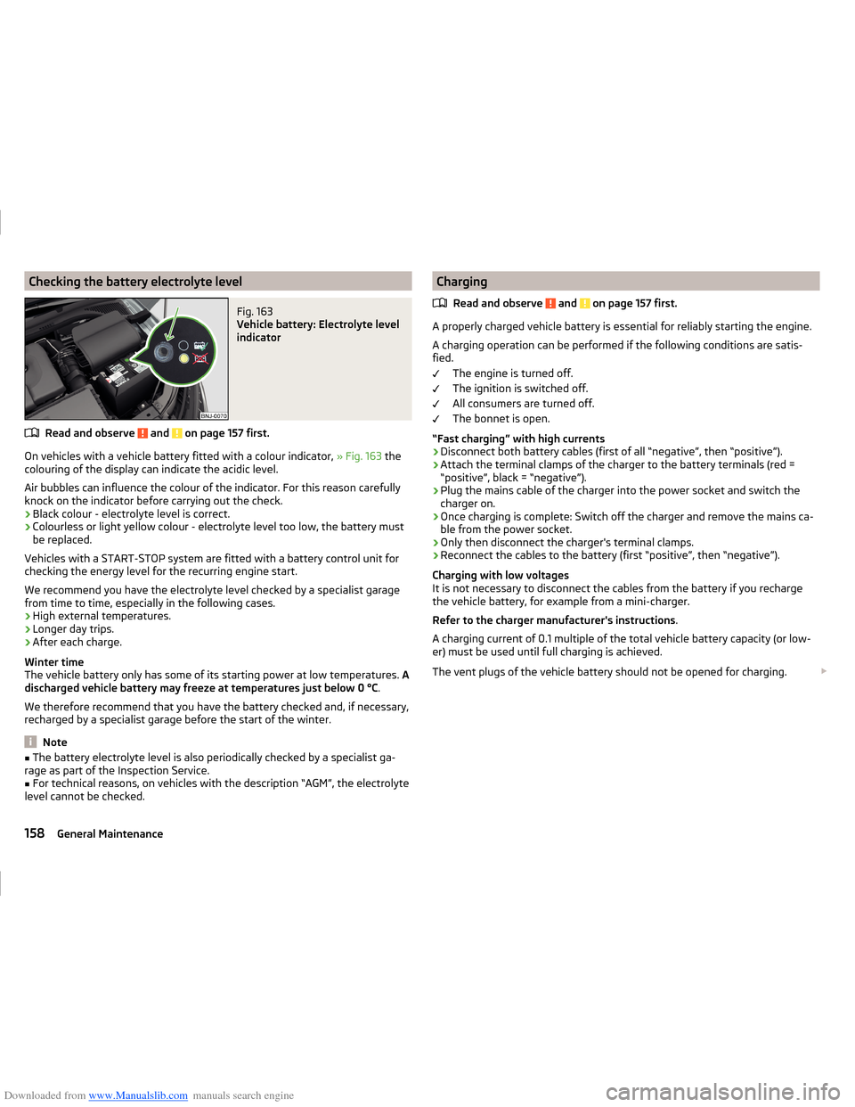
Downloaded from www.Manualslib.com manuals search engine Checking the battery electrolyte levelFig. 163
Vehicle battery: Electrolyte level
indicator
Read and observe and on page 157 first.
On vehicles with a vehicle battery fitted with a colour indicator, » Fig. 163 the
colouring of the display can indicate the acidic level.
Air bubbles can influence the colour of the indicator. For this reason carefully knock on the indicator before carrying out the check.
› Black colour - electrolyte level is correct.
› Colourless or light yellow colour - electrolyte level too low, the battery must
be replaced.
Vehicles with a START-STOP system are fitted with a battery control unit for
checking the energy level for the recurring engine start.
We recommend you have the electrolyte level checked by a specialist garage from time to time, especially in the following cases.
› High external temperatures.
› Longer day trips.
› After each charge.
Winter time
The vehicle battery only has some of its starting power at low temperatures. A
discharged vehicle battery may freeze at temperatures just below 0 °C .
We therefore recommend that you have the battery checked and, if necessary,
recharged by a specialist garage before the start of the winter.
Note
■ The battery electrolyte level is also periodically checked by a specialist ga-
rage as part of the Inspection Service.■
For technical reasons, on vehicles with the description “AGM”, the electrolyte
level cannot be checked.
Charging
Read and observe
and on page 157 first.
A properly charged vehicle battery is essential for reliably starting the engine.A charging operation can be performed if the following conditions are satis-
fied.
The engine is turned off.
The ignition is switched off.
All consumers are turned off.
The bonnet is open.
“Fast charging” with high currents
›
Disconnect both battery cables (first of all “negative”, then “positive”).
›
Attach the terminal clamps of the charger to the battery terminals (red =
“positive”, black = “negative”).
›
Plug the mains cable of the charger into the power socket and switch the
charger on.
›
Once charging is complete: Switch off the charger and remove the mains ca-
ble from the power socket.
›
Only then disconnect the charger's terminal clamps.
›
Reconnect the cables to the battery (first “positive”, then “negative”).
Charging with low voltages
It is not necessary to disconnect the cables from the battery if you recharge
the vehicle battery, for example from a mini-charger.
Refer to the charger manufacturer's instructions .
A charging current of 0.1 multiple of the total vehicle battery capacity (or low-
er) must be used until full charging is achieved.
The vent plugs of the vehicle battery should not be opened for charging.
158General Maintenance
Page 169 of 216

Downloaded from www.Manualslib.com manuals search engine Do-it-yourself
Emergency equipment, and self-help
Emergency equipment
Introduction
This chapter contains information on the following subjects:
Placement of the first aid kit and warning triangle
166
Placement of the reflective vest
166
Fire extinguisher
167
Vehicle tool kit
167
Placement of the first aid kit and warning triangle
Fig. 166
First aid kit and warning triangle
- Version 1
Fig. 167
First-aid kit and warning triangle - loosen version 2 / attachment
strap
The following information is for the first aid kit and warning triangle from the
ŠKODA Original accessories valid.
For another first aid kit and warning triangle the storage compartments may
possibly be too small.
First-aid box
The first-aid box can be attached by a strap to the right-hand side of the boot
» Fig. 166 or » Fig. 167 .
Warning triangle – version 1
The warning triangle can be stored in the rear wall trim panel » Fig. 166.
Warning triangle – version 2
The warning triangle can be placed in the panel at the right hand side of the
luggage compartment and secured to the fastening strap » Fig. 167.
Undo / secure fastening strap›
Press the latch on the connector in the direction of arrow
1
» Fig. 167 .
›
Release strap
A
in the direction of arrow
2
.
›
Pull strap
A
against arrow direction
2
until it locks into place.
WARNINGThe first-aid kit and warning triangle must always be secured safely so that
they do not come loose when making an emergency braking or in a vehicle
collision which could cause injuries to occupants.
Note
■ Pay attention to the expiration date of the first-aid kit.■We recommend using a first-aid box from ŠKODA Original Accessories availa-
ble from a ŠKODA Partner.
Placement of the reflective vest
Fig. 168
Storage compartment for the re-
flective vest
166Do-it-yourself
Page 170 of 216
Downloaded from www.Manualslib.com manuals search engine The reflective vest can be stowed in the storage compartment inside the stor-
age compartment of the door A» Fig. 168 .
Fire extinguisher
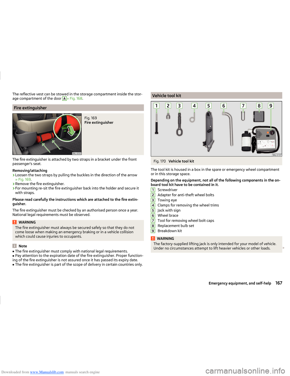
Fig. 169
Fire extinguisher
The fire extinguisher is attached by two straps in a bracket under the front
passenger's seat.
Removing/attaching
›
Loosen the two straps by pulling the buckles in the direction of the arrow
» Fig. 169 .
›
Remove the fire extinguisher.
›
For mounting re-sit the fire extinguisher back into the holder and secure it
with straps.
Please read carefully the instructions which are attached to the fire extin-
guisher.
The fire extinguisher must be checked by an authorised person once a year.
National legal requirements must be observed.
WARNINGThe fire extinguisher must always be secured safely so that they do not
come loose when making an emergency braking or in a vehicle collision
which could cause injuries to occupants.
Note
■ The fire extinguisher must comply with national legal requirements.■Pay attention to the expiration date of the fire extinguisher. Proper function-
ing of the fire extinguisher is not assured once it has passed its expiry date.■
The fire extinguisher is part of the scope of delivery in certain countries only.
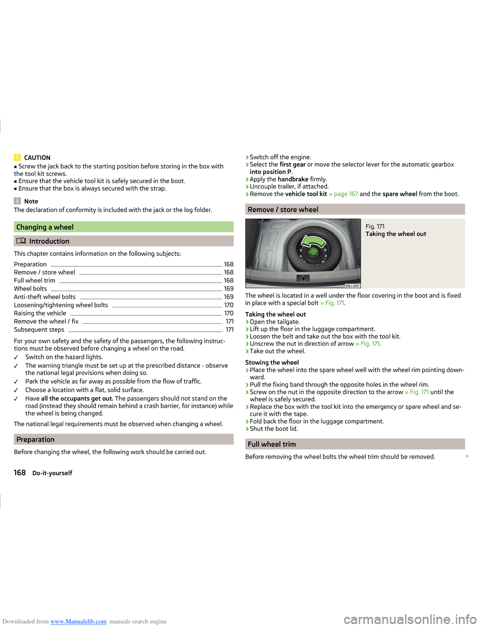
Vehicle tool kitFig. 170
Vehicle tool kit
The tool kit is housed in a box in the spare or emergency wheel compartment
or in this storage space.
Depending on the equipment, not all of the following components in the on-
board tool kit have to be contained in it.
Screwdriver
Adapter for anti-theft wheel bolts
Towing eye
Clamps for removing the wheel trims
Jack with sign
Wheel brace
Tool for removing wheel bolt caps
Replacement bulb set
Breakdown kit
WARNINGThe factory-supplied lifting jack is only intended for your model of vehicle.
Under no circumstances attempt to lift heavier vehicles or other loads. 123456789167Emergency equipment, and self-help
Page 171 of 216
Downloaded from www.Manualslib.com manuals search engine CAUTION■Screw the jack back to the starting position before storing in the box with
the tool kit screws.■
Ensure that the vehicle tool kit is safely secured in the boot.
■
Ensure that the box is always secured with the strap.
Note
The declaration of conformity is included with the jack or the log folder.
Changing a wheel
Introduction
This chapter contains information on the following subjects:
Preparation
168
Remove / store wheel
168
Full wheel trim
168
Wheel bolts
169
Anti-theft wheel bolts
169
Loosening/tightening wheel bolts
170
Raising the vehicle
170
Remove the wheel / fix
171
Subsequent steps
171
For your own safety and the safety of the passengers, the following instruc-
tions must be observed before changing a wheel on the road.
Switch on the hazard lights.
The warning triangle must be set up at the prescribed distance - observe
the national legal provisions when doing so.
Park the vehicle as far away as possible from the flow of traffic.
Choose a location with a flat, solid surface.
Have all the occupants get out. The passengers should not stand on the
road (instead they should remain behind a crash barrier, for instance) while
the wheel is being changed.
The national legal requirements must be observed when changing a wheel.
Preparation
Before changing the wheel, the following work should be carried out.
› Switch off the engine.›Select the
first gear or move the selector lever for the automatic gearbox
into position P .›
Apply the handbrake firmly.
›
Uncouple trailer, if attached.
›
Remove the vehicle tool kit » page 167 and the spare wheel from the boot.
Remove / store wheel
Fig. 171
Taking the wheel out
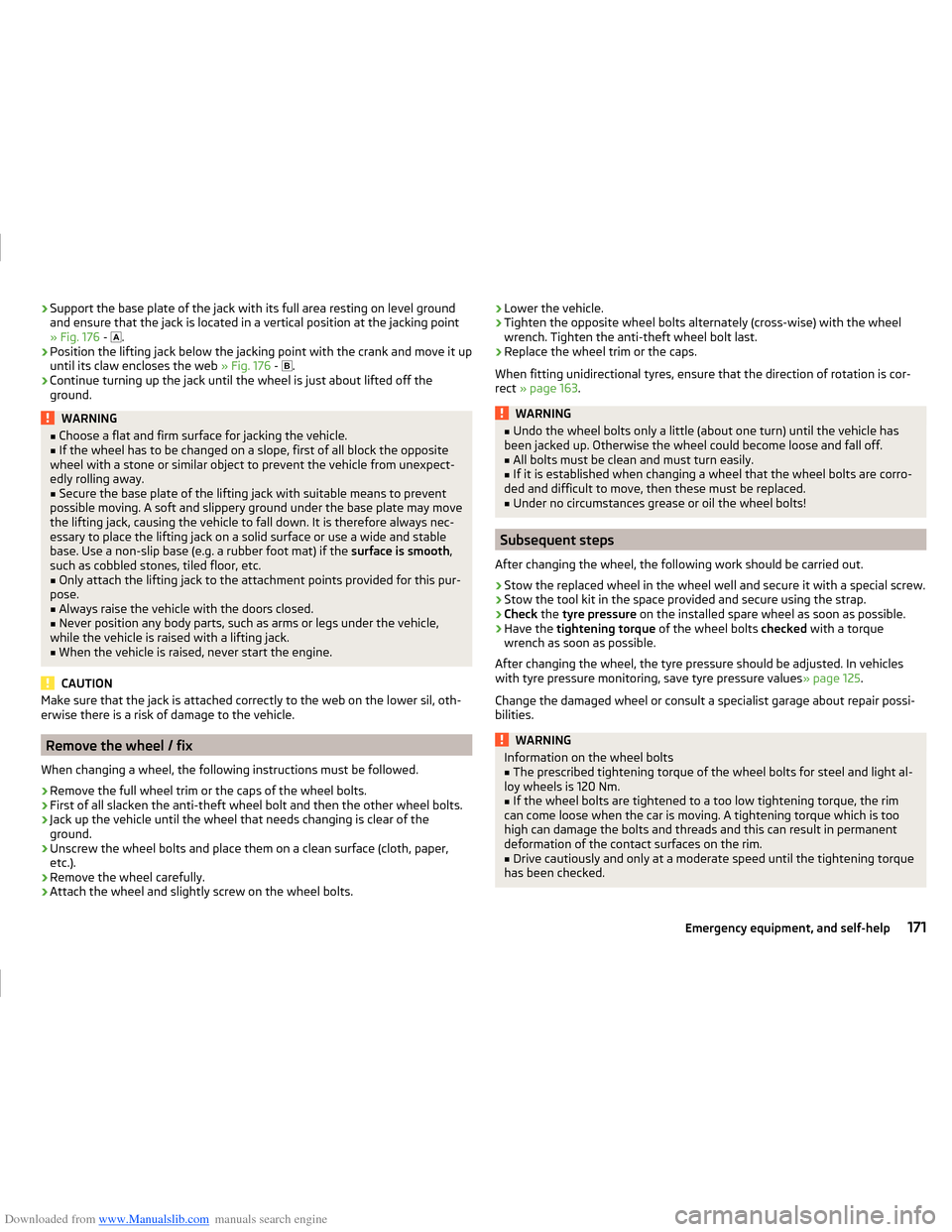
The wheel is located in a well under the floor covering in the boot and is fixed
in place with a special bolt » Fig. 171.
Taking the wheel out
›
Open the tailgate.
›
Lift up the floor in the luggage compartment.
›
Loosen the belt and take out the box with the tool kit.
›
Unscrew the nut in direction of arrow » Fig. 171.
›
Take out the wheel.
Stowing the wheel
›
Place the wheel into the spare wheel well with the wheel rim pointing down-
ward.
›
Pull the fixing band through the opposite holes in the wheel rim.
›
Screw on the nut in the opposite direction to the arrow » Fig. 171 until the
wheel is safely secured.
›
Replace the box with the tool kit into the emergency or spare wheel and se-
cure it with the tape.
›
Fold back the floor in the luggage compartment.
›
Shut the boot lid.
Full wheel trim
Before removing the wheel bolts the wheel trim should be removed.
168Do-it-yourself
Page 174 of 216
Downloaded from www.Manualslib.com manuals search engine ›Support the base plate of the jack with its full area resting on level ground
and ensure that the jack is located in a vertical position at the jacking point
» Fig. 176 -
.›
Position the lifting jack below the jacking point with the crank and move it up
until its claw encloses the web » Fig. 176 -
.
›
Continue turning up the jack until the wheel is just about lifted off the
ground.
WARNING■ Choose a flat and firm surface for jacking the vehicle.■If the wheel has to be changed on a slope, first of all block the opposite
wheel with a stone or similar object to prevent the vehicle from unexpect-
edly rolling away.■
Secure the base plate of the lifting jack with suitable means to prevent
possible moving. A soft and slippery ground under the base plate may move
the lifting jack, causing the vehicle to fall down. It is therefore always nec-
essary to place the lifting jack on a solid surface or use a wide and stable
base. Use a non-slip base (e.g. a rubber foot mat) if the surface is smooth,
such as cobbled stones, tiled floor, etc.
■
Only attach the lifting jack to the attachment points provided for this pur-
pose.
■
Always raise the vehicle with the doors closed.
■
Never position any body parts, such as arms or legs under the vehicle,
while the vehicle is raised with a lifting jack.
■
When the vehicle is raised, never start the engine.
CAUTION
Make sure that the jack is attached correctly to the web on the lower sil, oth-
erwise there is a risk of damage to the vehicle.
Remove the wheel / fix
When changing a wheel, the following instructions must be followed.
›
Remove the full wheel trim or the caps of the wheel bolts.
›
First of all slacken the anti-theft wheel bolt and then the other wheel bolts.
›
Jack up the vehicle until the wheel that needs changing is clear of the
ground.
›
Unscrew the wheel bolts and place them on a clean surface (cloth, paper, etc.).
›
Remove the wheel carefully.
›
Attach the wheel and slightly screw on the wheel bolts.
› Lower the vehicle.›Tighten the opposite wheel bolts alternately (cross-wise) with the wheel
wrench. Tighten the anti-theft wheel bolt last.›
Replace the wheel trim or the caps.
When fitting unidirectional tyres, ensure that the direction of rotation is cor-
rect » page 163 .
WARNING■
Undo the wheel bolts only a little (about one turn) until the vehicle has
been jacked up. Otherwise the wheel could become loose and fall off.■
All bolts must be clean and must turn easily.
■
If it is established when changing a wheel that the wheel bolts are corro-
ded and difficult to move, then these must be replaced.
■
Under no circumstances grease or oil the wheel bolts!
Subsequent steps
After changing the wheel, the following work should be carried out.
›
Stow the replaced wheel in the wheel well and secure it with a special screw.
›
Stow the tool kit in the space provided and secure using the strap.
›
Check the tyre pressure on the installed spare wheel as soon as possible.
›
Have the tightening torque of the wheel bolts checked with a torque
wrench as soon as possible.
After changing the wheel, the tyre pressure should be adjusted. In vehicles
with tyre pressure monitoring, save tyre pressure values » page 125.
Change the damaged wheel or consult a specialist garage about repair possi-
bilities.
WARNINGInformation on the wheel bolts■The prescribed tightening torque of the wheel bolts for steel and light al-
loy wheels is 120 Nm.■
If the wheel bolts are tightened to a too low tightening torque, the rim
can come loose when the car is moving. A tightening torque which is too
high can damage the bolts and threads and this can result in permanent
deformation of the contact surfaces on the rim.
■
Drive cautiously and only at a moderate speed until the tightening torque
has been checked.
171Emergency equipment, and self-help
Page 183 of 216
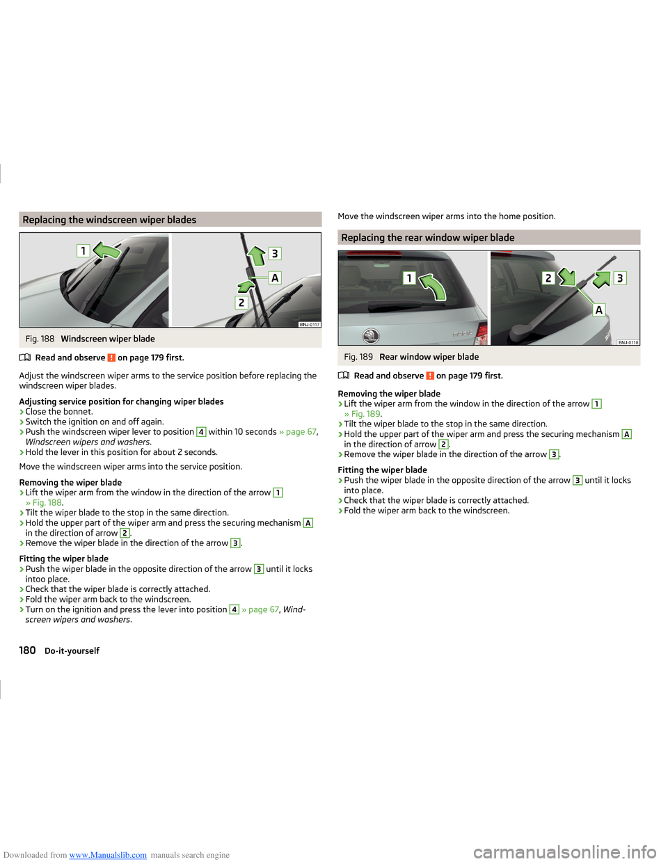
Downloaded from www.Manualslib.com manuals search engine Replacing the windscreen wiper bladesFig. 188
Windscreen wiper blade
Read and observe
on page 179 first.
Adjust the windscreen wiper arms to the service position before replacing the windscreen wiper blades.
Adjusting service position for changing wiper blades
›
Close the bonnet.
›
Switch the ignition on and off again.
›
Push the windscreen wiper lever to position
4
within 10 seconds » page 67,
Windscreen wipers and washers .
›
Hold the lever in this position for about 2 seconds.
Move the windscreen wiper arms into the service position.
Removing the wiper blade
›
Lift the wiper arm from the window in the direction of the arrow
1
» Fig. 188 .
›
Tilt the wiper blade to the stop in the same direction.
›
Hold the upper part of the wiper arm and press the securing mechanism
A
in the direction of arrow
2
.
›
Remove the wiper blade in the direction of the arrow
3
.
Fitting the wiper blade
›
Push the wiper blade in the opposite direction of the arrow
3
until it locks
intoo place.
›
Check that the wiper blade is correctly attached.
›
Fold the wiper arm back to the windscreen.
›
Turn on the ignition and press the lever into position
4
» page 67 , Wind-
screen wipers and washers .
Move the windscreen wiper arms into the home position.
Replacing the rear window wiper blade
Fig. 189
Rear window wiper blade
Read and observe
on page 179 first.
Removing the wiper blade
›
Lift the wiper arm from the window in the direction of the arrow
1
» Fig. 189 .
›
Tilt the wiper blade to the stop in the same direction.
›
Hold the upper part of the wiper arm and press the securing mechanism
A
in the direction of arrow
2
.
›
Remove the wiper blade in the direction of the arrow
3
.
Fitting the wiper blade
›
Push the wiper blade in the opposite direction of the arrow
3
until it locks
into place.
›
Check that the wiper blade is correctly attached.
›
Fold the wiper arm back to the windscreen.
180Do-it-yourself
Page 186 of 216
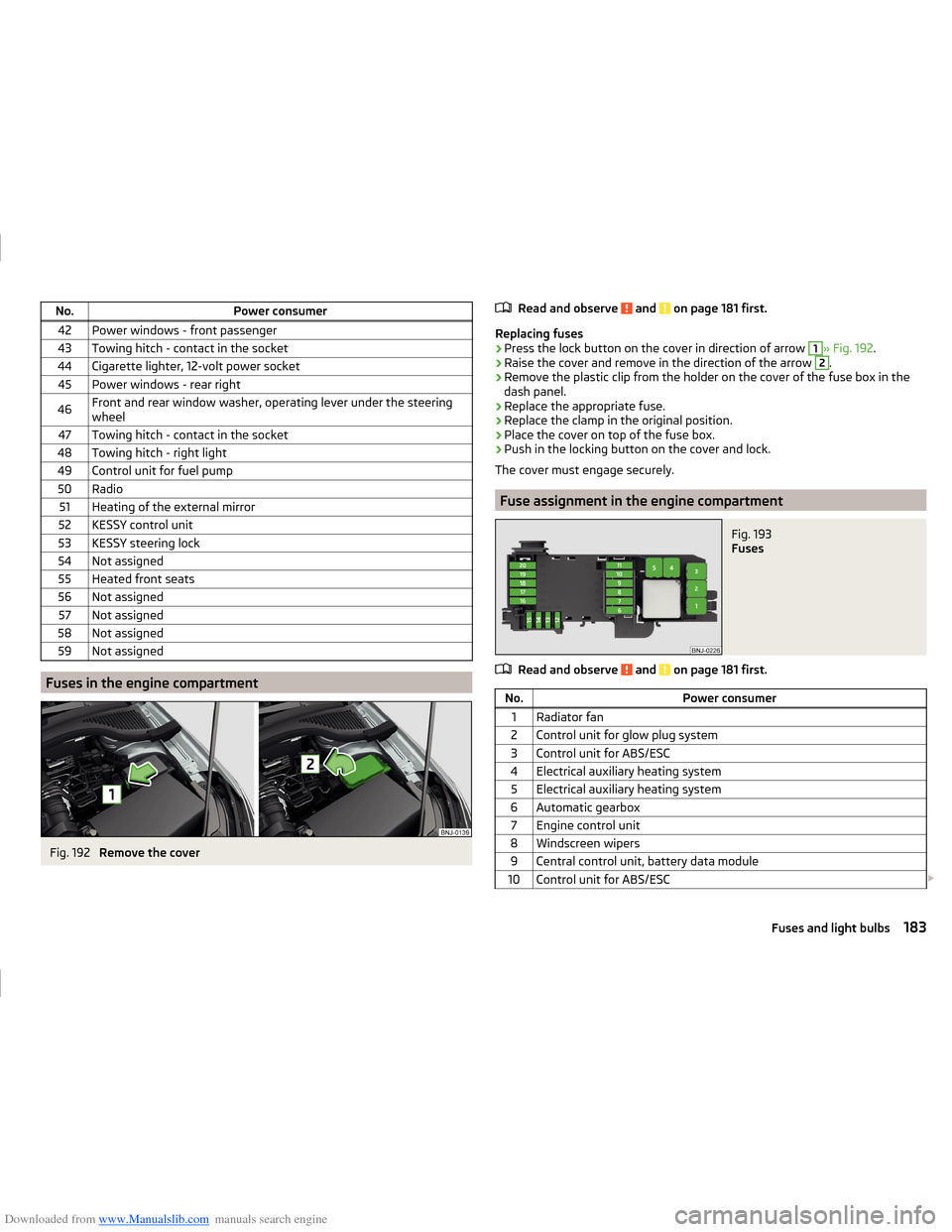
Downloaded from www.Manualslib.com manuals search engine No.Power consumer42Power windows - front passenger43Towing hitch - contact in the socket44Cigarette lighter, 12-volt power socket45Power windows - rear right46Front and rear window washer, operating lever under the steering
wheel47Towing hitch - contact in the socket48Towing hitch - right light49Control unit for fuel pump50Radio51Heating of the external mirror52KESSY control unit53KESSY steering lock54Not assigned55Heated front seats56Not assigned57Not assigned58Not assigned59Not assigned
Fuses in the engine compartment
Fig. 192
Remove the cover
Read and observe and on page 181 first.
Replacing fuses
›
Press the lock button on the cover in direction of arrow
1
» Fig. 192 .
›
Raise the cover and remove in the direction of the arrow
2
.
›
Remove the plastic clip from the holder on the cover of the fuse box in the
dash panel.
›
Replace the appropriate fuse.
›
Replace the clamp in the original position.
›
Place the cover on top of the fuse box.
›
Push in the locking button on the cover and lock.
The cover must engage securely.
Fuse assignment in the engine compartment
Fig. 193
Fuses
Read and observe and on page 181 first.
No.Power consumer1Radiator fan2Control unit for glow plug system3Control unit for ABS/ESC4Electrical auxiliary heating system5Electrical auxiliary heating system6Automatic gearbox7Engine control unit8Windscreen wipers9Central control unit, battery data module10Control unit for ABS/ESC 183Fuses and light bulbs