boot SKODA FABIA 2014 3.G / NJ Operating Instruction Manual
[x] Cancel search | Manufacturer: SKODA, Model Year: 2014, Model line: FABIA, Model: SKODA FABIA 2014 3.G / NJPages: 216, PDF Size: 30.9 MB
Page 63 of 216
Downloaded from www.Manualslib.com manuals search engine Note■The headlights may mist up temporarily. When the driving lights are switched
on, the light outlet areas are free from condensation after a short time, al-
though the headlight lenses may still be misted up around the edge. This mist
has no influence on the life of the lighting system.■
The instruments are also illuminated when the parking light, low or high
beam light is switched on. The brightness of the instrument illumination is set
automatically depending on the ambient lighting throughout. The complete
brightness of the instrument lighting can be set in the Infotainment » Operat-
ing instructions Infotainment , chapter CAR - Vehicle settings .
Operating the lights
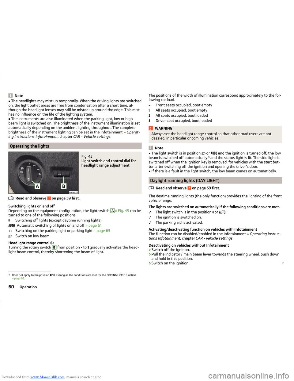
Fig. 45
Light switch and control dial for
headlight range adjustment
Read and observe on page 59 first.
Switching lights on and off
Depending on the equipment configuration, the light switch
A
» Fig. 45 can be
turned to one of the following positions.
Switching off lights (except daytime running lights)Automatic switching of lights on and off » page 61
Switching on the parking light or parking light » page 63
Switch on low beam
Headlight range control
Turning the rotary switch
B
from position - to
gradually activates the head-
light beam control, thereby shortening the beam of light.
The positions of the width of illumination correspond approximately to the fol-
lowing car load.
Front seats occupied, boot empty
All seats occupied, boot empty
All seats occupied, boot loaded
Driver seat occupied, boot loadedWARNINGAlways set the headlight range control so that other road users are not
dazzled, in particular oncoming vehicles.
Note
■ The light switch is in position or and the ignition is turned off, the low
beam is switched off automatically 1)
and the status light is lit. The side light is
switched off when the ignition key is removed, for vehicles with the start but-
ton after switching off the ignition and opening the driver's door.■
If there is a fault in the light switch, the low beam comes on automatically.
Daylight running lights (DAY LIGHT)
Read and observe
on page 59 first.
The daytime running lights (the only function) provides the lighting of the frontvehicle range.
The lights are switched on automatically if the following conditions are met. The light switch is in the position
or
.
The ignition is switched on.
The parking aid is activated.
Activating/deactivating function on vehicles with Infotainment
The function can be disabled/enabled in the Infotainment » Operating instruc-
tions Infotainment , chapter CAR - vehicle settings .
Deactivating on vehicles without Infotainment
›
Switch off the ignition.
›
Pull the indicator / main beam lever towards the steering wheel, push down
and hold in this position.
›
Switch on the ignition.
1)
Does not apply to the position
, as long as the conditions are met for the COMING HOME function
» page 63 .
60Operation
Page 86 of 216
Downloaded from www.Manualslib.com manuals search engine Luggage compartment
Introduction
This chapter contains information on the following subjects:
Fastening elements
84
Fixing nets
84
Hooks
85
Storage compartments in the luggage compartment
85
Luggage compartment cover
86
Other positions of the luggage compartment cover
86
Roll-up cover
87
Storage compartments under the floor
87
Cargo element
88
Flexible storage compartment
88
Class N1 vehicles
88
Please observe the following for the purpose of maintaining good handling
characteristics of your vehicle:
›
Distribute loads as evenly as possible.
›
Place heavy objects as far forward as possible.
›
Attach the items of luggage to the lashing eyes or by using the fixing nets
» page 84 .
In the event of an accident, even small and light objects gain so much kinetic energy that they can cause severe injuries.
The magnitude of the kinetic energy is dependent on the speed at which the
vehicle is travelling and the weight of the object.
Example: In the event of a frontal collision at a speed of 50 km/h, an object
weighing 4.5 kg produces energy corresponding to 20 times its own weight.
This means that it results in a weight of approx. 90 kg “ ”.
Luggage compartment light
The warning light turns on when tailgate is opened.
The warning light turns off when the tailgate is closed.
If the boot lid is open and the ignition switched off, the light will extinguish
automatically after around 10 minutes.
WARNING■ Always store transported objects in the boot and attach them to the lash-
ing eyes.■
Loose objects can be thrown forward during a sudden manoeuvre or in
case of an accident and can injure the occupants or other road users.
■
Loose objects could hit a deployed airbag and injure occupants – risk to
life!
■
Please note that the handling properties of the vehicle may be affected
when transporting heavy objects as the centre of gravity can be shifted –
risk of accident. The speed and style of driving must be adjusted according-
ly.
■
If the items of luggage or objects are attached to the lashing eyes with
unsuitable or damaged lashing straps, injuries can occur in the event of
braking manoeuvres or accidents. To prevent items of luggage from moving
around, always use suitable lashing straps that are firmly attached to the
lashing eyes.
■
Items carried in the luggage compartment must be stowed in such a way
that no objects are able to slip forward under sudden driving manoeuvres
or braking – risk of injury.
■
When transporting objects in the luggage compartment that has been en-
larged by folding the rear seats forward, ensure the safety of the passen-
gers transported on the other rear seats » page 10.
■
Do not drive with the luggage compartment lid open or unlatched, other-
wise exhaust gases may get into the interior of the vehicle – risk of poison-
ing!
■
Do not exceed the permissible axle loads and permissible gross weight of
the vehicle – risk of accident!
■
Do not transport people in the boot!
CAUTION
■ Please ensure that the heating elements for the rear window heater are not
damaged as a result of abrasive objects.■
Tyre pressure must be adjusted to the load » page 161.
83Transporting and practical equipment
Page 89 of 216
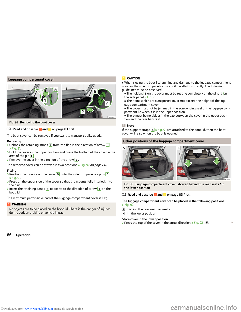
Downloaded from www.Manualslib.com manuals search engine Luggage compartment coverFig. 91
Removing the boot cover
Read and observe
and on page 83 first.
The boot cover can be removed if you want to transport bulky goods.
Removing
›
Unhook the retaining straps
A
from the flap in the direction of arrow
1
» Fig. 91 .
›
Hold the cover in the upper position and press the bottom of the cover in the
area of the pin
C
.
›
Remove the cover in the direction of the arrow
2
.
The removed cover can be stowed in two positions » Fig. 92 on page 86 .
Fitting
›
Position the mounts on the cover
B
onto the side trim panel via pins
C
» Fig. 91 .
›
Press on the upper side of the cover so that the mounts fully interlock into
the pins.
›
Insert the retaining bands
A
opposite to the direction of arrow
1
on the
boot lid.
The maximum permissible load of the luggage compartment cover is 1 kg.
WARNINGNo objects are to be placed on the boot lid. There is the danger of injuries
during sudden braking or vehicle impact.CAUTION■ When closing the boot lid, jamming and damage to the luggage compartment
cover or the side trim panel can occur if handled incorrectly. The following
guidelines must be observed. ■ The holders B
on the cover must be resting completely on the pins
C
on
the side panel » Fig. 91.
■ The items which are transported must not exceed the height of the lug-
gage compartment cover. ■ The cover must not be jammed in the surrounding seal of the luggage com-
partment lid when it is in the upper position.
■ There must be no object in the gap between the cover in the upper posi-
tion and the rear backrest.
Note
If the support straps A » Fig. 91 are attached to the boot lid, then the boot
cover will raise when the boot is opened.
Other positions of the luggage compartment cover
Fig. 92
Luggage compartment cover: stowed behind the rear seats / in
the lower position
Read and observe
and on page 83 first.
The luggage compartment cover can be placed in the following positions:
» Fig. 92
Behind the rear seat backrests
In the lower position
Store cover in the lower position
›
Press the top of the cover in the arrow direction » Fig. 92 -
.
86Operation
Page 90 of 216

Downloaded from www.Manualslib.com manuals search engine In the front area, slots B » Fig. 91 on page 86 on the cover must be fully en-
gaged with the bolts on the side trim. In the back, the cover must be secured
at both ends under the latching.
In the lower position, the cover is designed for storing small objects up to a
weight of 2.5 kg in total.
Roll-up cover
Fig. 93
Roll-up cover: Pull-out / roll-up / remove
Read and observe
and on page 83 first.
Pulling out
›
Grasp the cover on handle
A
and pull it out in the direction of the arrow
1
until it clicks audibly into the secured position » Fig. 93.
Rolling up
›
Push the cover in the area of handle
A
in the direction of the arrow
2
» Fig. 93 .
The cover rolls up automatically.
Removing
›
The cover can be rolled up before removing.
›
Press on the side of the cross bar in the direction of arrow
3
and remove
the cover in the arrow direction
4
» Fig. 93 .
Inserting
›
First insert the cover on the left side.
›
Press on the side of the cross bar in the direction of arrow
3
and insert the
cover against arrow direction
4
» Fig. 93 .
WARNINGNo objects should be placed on the foldable boot cover. There is the danger
of injuries during sudden braking or vehicle impact.
Storage compartments under the floor
Fig. 94
Fold the floor back / storage compartment under the floor
Read and observe
and on page 83 first.
The storage compartment is located under the luggage compartment floor
» Fig. 94 -
.
›
Lift the rear portion of the floor and fold forward in the direction of arrow
» Fig. 94 -
.
The storage compartment is designed for storing small objects of up to 15 kg. in weight in total.
CAUTION
■ The following instructions must be observed to avoid damage to the storage
compartment. ■ Do not store any sharp objects in the storage compartment.
■ Place the items carefully into the storage compartment.
■ Do not place pressure on any points in the storage compartment.87Transporting and practical equipment
Page 91 of 216
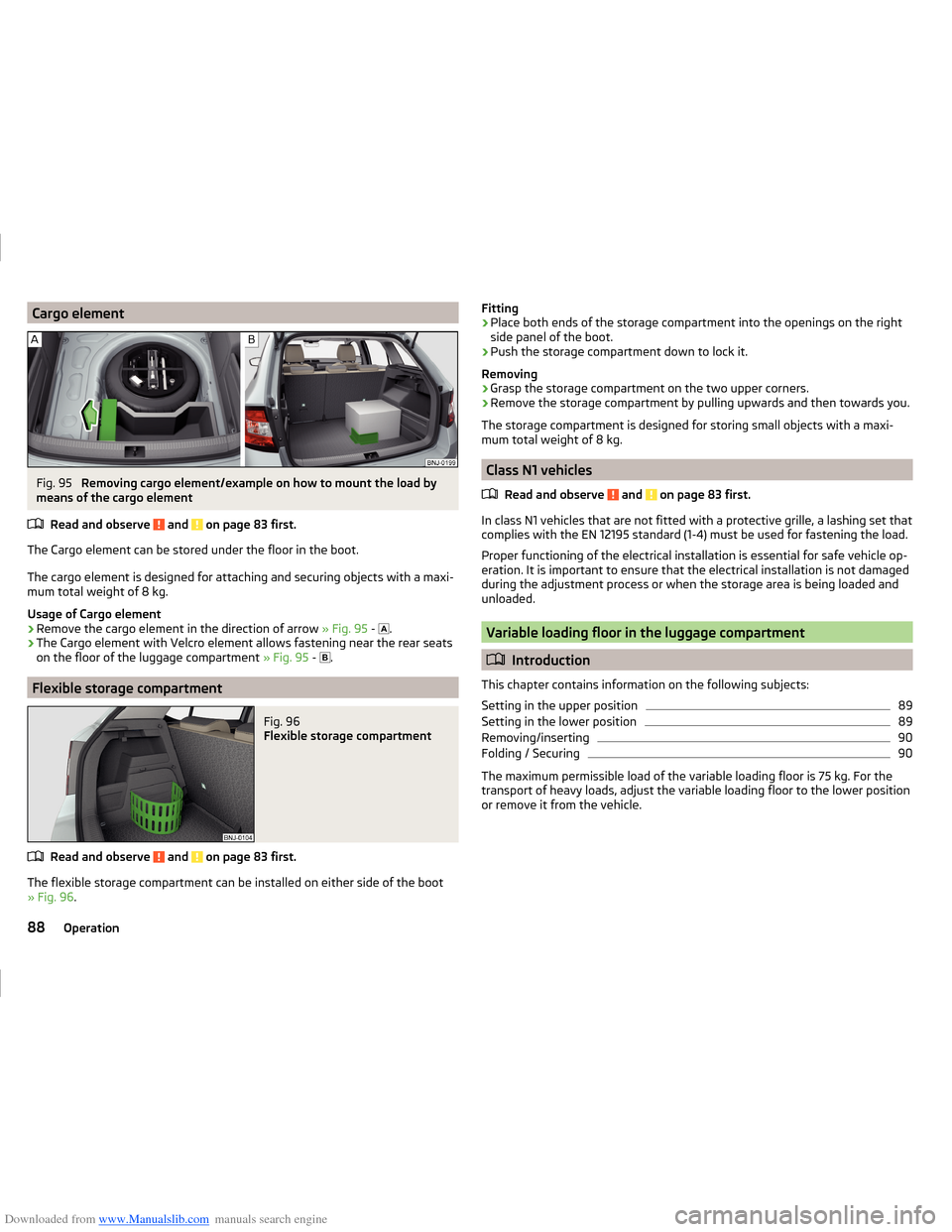
Downloaded from www.Manualslib.com manuals search engine Cargo elementFig. 95
Removing cargo element/example on how to mount the load by
means of the cargo element
Read and observe
and on page 83 first.
The Cargo element can be stored under the floor in the boot.
The cargo element is designed for attaching and securing objects with a maxi-
mum total weight of 8 kg.
Usage of Cargo element
›
Remove the cargo element in the direction of arrow » Fig. 95 -
.
›
The Cargo element with Velcro element allows fastening near the rear seats
on the floor of the luggage compartment » Fig. 95 -
.
Flexible storage compartment
Fig. 96
Flexible storage compartment
Read and observe and on page 83 first.
The flexible storage compartment can be installed on either side of the boot
» Fig. 96 .
Fitting›Place both ends of the storage compartment into the openings on the right
side panel of the boot.›
Push the storage compartment down to lock it.
Removing
›
Grasp the storage compartment on the two upper corners.
›
Remove the storage compartment by pulling upwards and then towards you.
The storage compartment is designed for storing small objects with a maxi-
mum total weight of 8 kg.
Class N1 vehicles
Read and observe
and on page 83 first.
In class N1 vehicles that are not fitted with a protective grille, a lashing set that
complies with the EN 12195 standard (1-4) must be used for fastening the load.
Proper functioning of the electrical installation is essential for safe vehicle op-
eration. It is important to ensure that the electrical installation is not damaged
during the adjustment process or when the storage area is being loaded and
unloaded.
Variable loading floor in the luggage compartment
Introduction
This chapter contains information on the following subjects:
Setting in the upper position
89
Setting in the lower position
89
Removing/inserting
90
Folding / Securing
90
The maximum permissible load of the variable loading floor is 75 kg. For the
transport of heavy loads, adjust the variable loading floor to the lower position
or remove it from the vehicle.
88Operation
Page 93 of 216
Downloaded from www.Manualslib.com manuals search engine Removing/insertingFig. 99
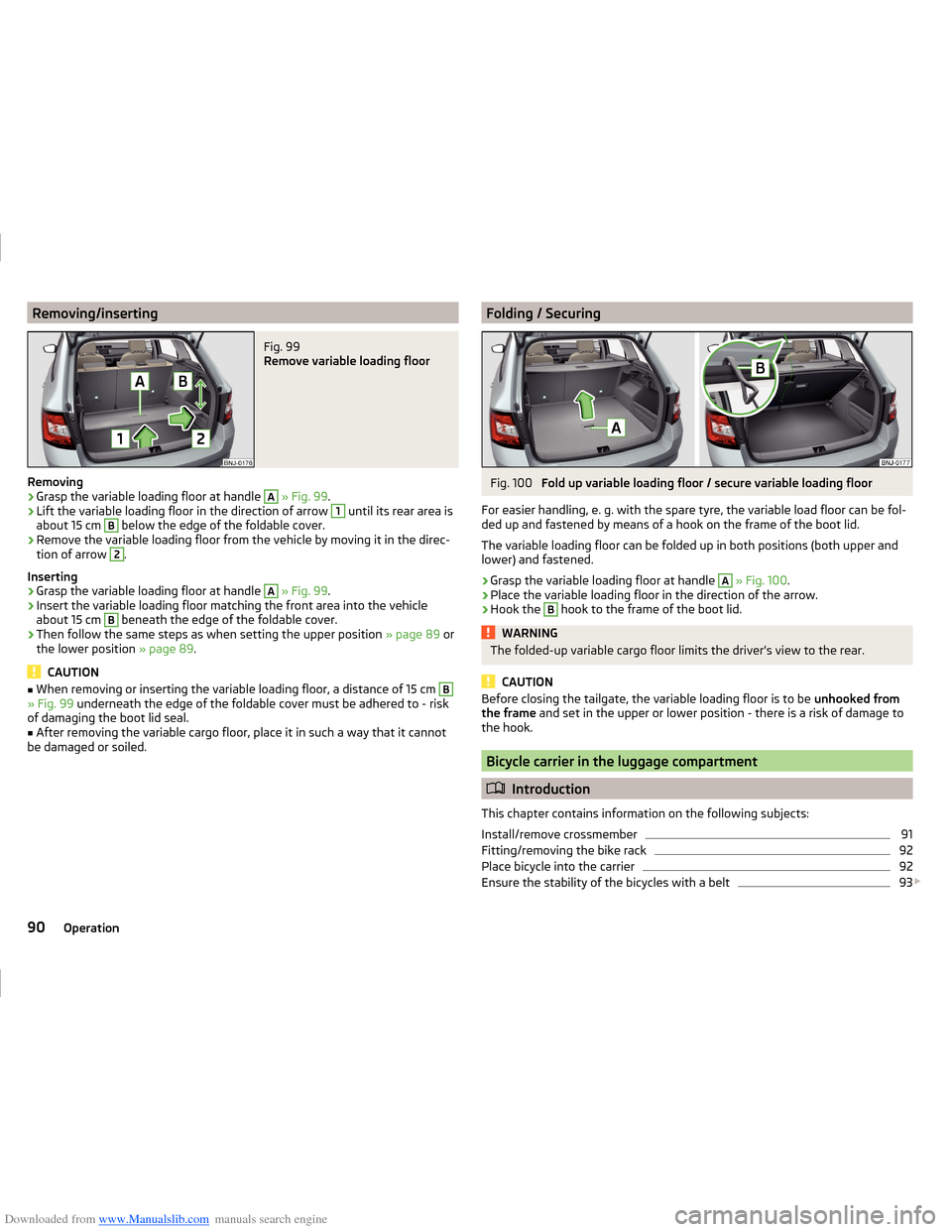
Remove variable loading floor
Removing
›
Grasp the variable loading floor at handle
A
» Fig. 99 .
›
Lift the variable loading floor in the direction of arrow
1
until its rear area is
about 15 cm
B
below the edge of the foldable cover.
›
Remove the variable loading floor from the vehicle by moving it in the direc-
tion of arrow
2
.
Inserting
›
Grasp the variable loading floor at handle
A
» Fig. 99 .
›
Insert the variable loading floor matching the front area into the vehicle
about 15 cm
B
beneath the edge of the foldable cover.
›
Then follow the same steps as when setting the upper position » page 89 or
the lower position » page 89.
CAUTION
■
When removing or inserting the variable loading floor, a distance of 15 cm B» Fig. 99 underneath the edge of the foldable cover must be adhered to - risk
of damaging the boot lid seal.■
After removing the variable cargo floor, place it in such a way that it cannot
be damaged or soiled.
Folding / SecuringFig. 100
Fold up variable loading floor / secure variable loading floor
For easier handling, e. g. with the spare tyre, the variable load floor can be fol-
ded up and fastened by means of a hook on the frame of the boot lid.
The variable loading floor can be folded up in both positions (both upper and
lower) and fastened.
›
Grasp the variable loading floor at handle
A
» Fig. 100 .
›
Place the variable loading floor in the direction of the arrow.
›
Hook the
B
hook to the frame of the boot lid.
WARNINGThe folded-up variable cargo floor limits the driver's view to the rear.
CAUTION
Before closing the tailgate, the variable loading floor is to be unhooked from
the frame and set in the upper or lower position - there is a risk of damage to
the hook.
Bicycle carrier in the luggage compartment
Introduction
This chapter contains information on the following subjects:
Install/remove crossmember
91
Fitting/removing the bike rack
92
Place bicycle into the carrier
92
Ensure the stability of the bicycles with a belt
93
90Operation
Page 95 of 216
Downloaded from www.Manualslib.com manuals search engine Fitting/removing the bike rackFig. 103
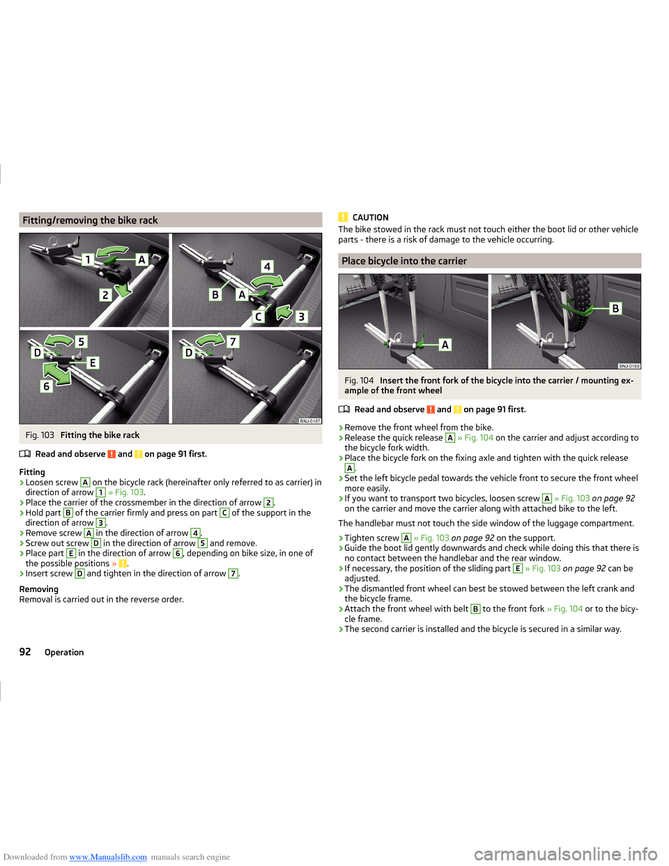
Fitting the bike rack
Read and observe
and on page 91 first.
Fitting
›
Loosen screw
A
on the bicycle rack (hereinafter only referred to as carrier) in
direction of arrow
1
» Fig. 103 .
›
Place the carrier of the crossmember in the direction of arrow
2
.
›
Hold part
B
of the carrier firmly and press on part
C
of the support in the
direction of arrow
3
.
›
Remove screw
A
in the direction of arrow
4
.
›
Screw out screw
D
in the direction of arrow
5
and remove.
›
Place part
E
in the direction of arrow
6
, depending on bike size, in one of
the possible positions » .
›
Insert screw
D
and tighten in the direction of arrow
7
.
Removing
Removal is carried out in the reverse order.
CAUTIONThe bike stowed in the rack must not touch either the boot lid or other vehicle
parts - there is a risk of damage to the vehicle occurring.
Place bicycle into the carrier
Fig. 104
Insert the front fork of the bicycle into the carrier / mounting ex-
ample of the front wheel
Read and observe
and on page 91 first.
›
Remove the front wheel from the bike.
›
Release the quick release
A
» Fig. 104 on the carrier and adjust according to
the bicycle fork width.
›
Place the bicycle fork on the fixing axle and tighten with the quick release
A
.
›
Set the left bicycle pedal towards the vehicle front to secure the front wheel
more easily.
›
If you want to transport two bicycles, loosen screw
A
» Fig. 103 on page 92
on the carrier and move the carrier along with attached bike to the left.
The handlebar must not touch the side window of the luggage compartment.
›
Tighten screw
A
» Fig. 103 on page 92 on the support.
›
Guide the boot lid gently downwards and check while doing this that there is
no contact between the handlebar and the rear window.
›
If necessary, the position of the sliding part
E
» Fig. 103 on page 92 can be
adjusted.
›
The dismantled front wheel can best be stowed between the left crank and
the bicycle frame.
›
Attach the front wheel with belt
B
to the front fork » Fig. 104 or to the bicy-
cle frame.
›
The second carrier is installed and the bicycle is secured in a similar way.
92Operation
Page 96 of 216
Downloaded from www.Manualslib.com manuals search engine Ensure the stability of the bicycles with a beltFig. 105
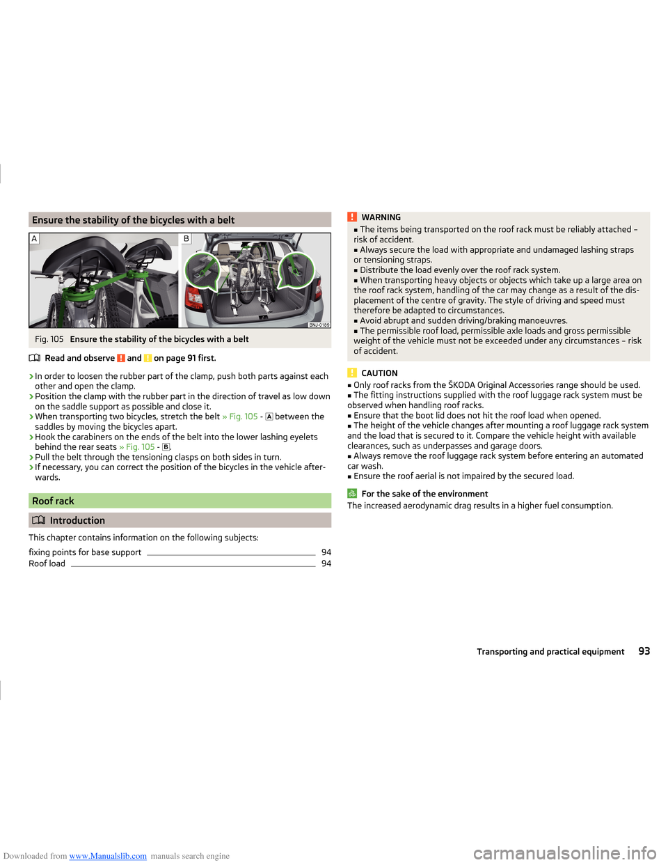
Ensure the stability of the bicycles with a belt
Read and observe
and on page 91 first.
›
In order to loosen the rubber part of the clamp, push both parts against each
other and open the clamp.
›
Position the clamp with the rubber part in the direction of travel as low down
on the saddle support as possible and close it.
›
When transporting two bicycles, stretch the belt » Fig. 105 -
between the
saddles by moving the bicycles apart.
›
Hook the carabiners on the ends of the belt into the lower lashing eyelets
behind the rear seats » Fig. 105 -
.
›
Pull the belt through the tensioning clasps on both sides in turn.
›
If necessary, you can correct the position of the bicycles in the vehicle after-
wards.
Roof rack
Introduction
This chapter contains information on the following subjects:
fixing points for base support
94
Roof load
94WARNING■ The items being transported on the roof rack must be reliably attached –
risk of accident.■
Always secure the load with appropriate and undamaged lashing straps
or tensioning straps.
■
Distribute the load evenly over the roof rack system.
■
When transporting heavy objects or objects which take up a large area on
the roof rack system, handling of the car may change as a result of the dis-
placement of the centre of gravity. The style of driving and speed must
therefore be adapted to circumstances.
■
Avoid abrupt and sudden driving/braking manoeuvres.
■
The permissible roof load, permissible axle loads and gross permissible
weight of the vehicle must not be exceeded under any circumstances – risk
of accident.
CAUTION
■ Only roof racks from the ŠKODA Original Accessories range should be used.■The fitting instructions supplied with the roof luggage rack system must be
observed when handling roof racks.■
Ensure that the boot lid does not hit the roof load when opened.
■
The height of the vehicle changes after mounting a roof luggage rack system
and the load that is secured to it. Compare the vehicle height with available
clearances, such as underpasses and garage doors.
■
Always remove the roof luggage rack system before entering an automated
car wash.
■
Ensure the roof aerial is not impaired by the secured load.
For the sake of the environment
The increased aerodynamic drag results in a higher fuel consumption.93Transporting and practical equipment
Page 134 of 216
Downloaded from www.Manualslib.com manuals search engine Removing the bar ball - 1. StepFig. 149
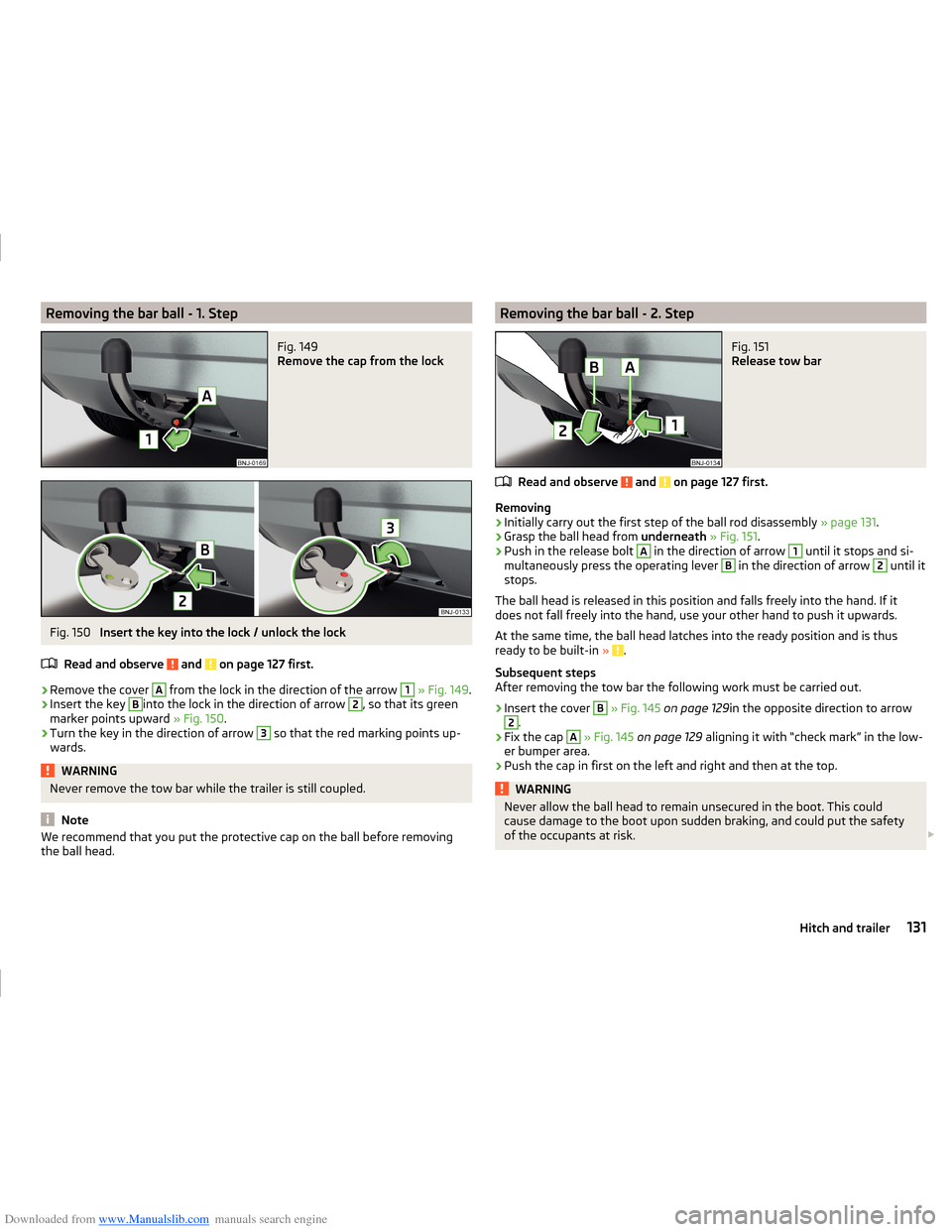
Remove the cap from the lock
Fig. 150
Insert the key into the lock / unlock the lock
Read and observe
and on page 127 first.
›
Remove the cover
A
from the lock in the direction of the arrow
1
» Fig. 149 .
›
Insert the key
B
into the lock in the direction of arrow
2
, so that its green
marker points upward » Fig. 150.
›
Turn the key in the direction of arrow
3
so that the red marking points up-
wards.
WARNINGNever remove the tow bar while the trailer is still coupled.
Note
We recommend that you put the protective cap on the ball before removing
the ball head.Removing the bar ball - 2. StepFig. 151
Release tow bar
Read and observe and on page 127 first.
Removing
›
Initially carry out the first step of the ball rod disassembly » page 131.
›
Grasp the ball head from underneath » Fig. 151 .
›
Push in the release bolt
A
in the direction of arrow
1
until it stops and si-
multaneously press the operating lever
B
in the direction of arrow
2
until it
stops.
The ball head is released in this position and falls freely into the hand. If it
does not fall freely into the hand, use your other hand to push it upwards.
At the same time, the ball head latches into the ready position and is thus
ready to be built-in »
.
Subsequent steps
After removing the tow bar the following work must be carried out.
›
Insert the cover
B
» Fig. 145 on page 129 in the opposite direction to arrow
2
.
›
Fix the cap
A
» Fig. 145 on page 129 aligning it with “check mark” in the low-
er bumper area.
›
Push the cap in first on the left and right and then at the top.
WARNINGNever allow the ball head to remain unsecured in the boot. This could
cause damage to the boot upon sudden braking, and could put the safety
of the occupants at risk. 131Hitch and trailer
Page 148 of 216
Downloaded from www.Manualslib.com manuals search engine ■Do not attach any stickers to the filaments or glass antenna - there is risk of
damage.■
Do not clean the headlining with a brush – risk of damage to the lining sur-
face.
■
Cleaners containing solvents can damage the material being cleaned.
■
Apply only a small amount of the cleaning and care product.
For the sake of the environment
Used cans of vehicle care product represent hazardous waste that is harmful
to the environment. These must be disposed of in accordance with national
legislation.
Note
Because of the special tools and knowledge required, and to avoid any poten-
tial problems with the cleaning and care of the interior of your vehicle, we rec-
ommend that cleaning and care of the interior of your vehicle be carried out by
a ŠKODA Service Partner.
Natural leather
Read and observe
and on page 144 first.
The leather needs, depending on the strain placed on it, regular cleaning and
maintenance.
Dust and dirt in pores and creases cause abrasions on the surface and lead to
premature brittling of the leather surface. Therefore, they must be removed
regularly at short intervals with a cloth or vacuum cleaner.
Clean soiled leather surfaces with a cotton or woollen cloth lightly moistened
with water and then dry with a clean dry cloth »
.
Clean more severely soiled areas with a cloth soaked in a mild soap solution (2
tablespoons of natural soap to 1 litre of water).
To remove stains , use a cleaning agent specially designed for this purpose.
Treat the leather periodically with a suitable leather protector and use a skin
care cream with light blocker and impregnation after each cleaning.
CAUTION■ Ensure that the leather is not soaked through at any point during cleaning
and that no water gets into the stitching of the seams. The leather would then
become brittle and cracked.■
Avoid leaving the vehicle for lengthy periods in bright sunlight to avoid the
leather from bleaching. If the vehicle is parked in the open for lengthy periods,
protect the leather from direct sunlight by covering it.
■
The use of an additional mechanical steering wheel lock may damage the
leather surface of the steering wheel.
■
Some clothing materials, such as dark denim, do not have sufficient colour
fastness. This can cause damage or clearly visible discolouration to seat covers
even when treated correctly. This is particularly true for light-coloured uphols-
tery. This is not a defect in the seat cover, but poor colour fastness of the
clothing textiles.
■
Sharp-edged objects on items of clothing such as zip fasteners, rivets, sharp-
edged belts etc. may leave permanent scratches or signs of rubbing on the
surface or damage these. Damage of this nature cannot later be recognized as
a justified complaint.
Note
During the life of the vehicle, minor visible changes can occur on the leather
parts of the covers (e. g wrinkles or creases as a result of the stress of the cov-
ers).
Artificial leather, materials and Alcantara ®
Read and observe
and on page 144 first.
Synthetic leather
Clean the synthetic leather with a damp cloth.
If the synthetic leather does not come completely clean with this method, a
mild soap solution or specific cleaning agent must be used.
Fabrics
Clean upholstery cover materials and cloth trims on doors, boot cover, etc. us-
ing specific cleaning agents, e.g., dry foam.
Use a soft sponge, brush, or commercially available microfibre cloth.
Use a cloth and special detergent to clean the headlining.
Remove pilling and residues on upholstery with a brush.
Remove stubborn hair with a “cleaning glove”.
145Care and maintenance