towing SKODA FABIA 2014 3.G / NJ Operating Instruction Manual
[x] Cancel search | Manufacturer: SKODA, Model Year: 2014, Model line: FABIA, Model: SKODA FABIA 2014 3.G / NJPages: 216, PDF Size: 30.9 MB
Page 133 of 216
Downloaded from www.Manualslib.com manuals search engine The operating lever C automatically turns upwards in the direction of arrow4 and the release pin D pops out (both its red and green parts are visible)
» .
If the operating lever
C
does not turn automatically, or if the release pin
D
does not pop out, remove the tow bar from the mounting recess by turning the
operating lever
C
downwards as far as it can go. Clean the contact surfaces
on the tow bar and the mounting recess.
WARNING■ Carefully remove the cap for the mounting recess B - there is a risk of
hand injury.■
Keep your hands outside the operating lever's range of motion when at-
taching the ball head – there is a risk of finger injury.
■
Never attempt to pull the operating lever upwards forcibly to turn the
key. Doing so would mean the ball head is not attached correctly.
CAUTION
Remove the cover A from the rear bumper with care - there is a risk of paint
damage to the bumper and the cap.
Note
Store the caps A and B » Fig. 145 in a suitable place in the luggage compart-
ment after removal.
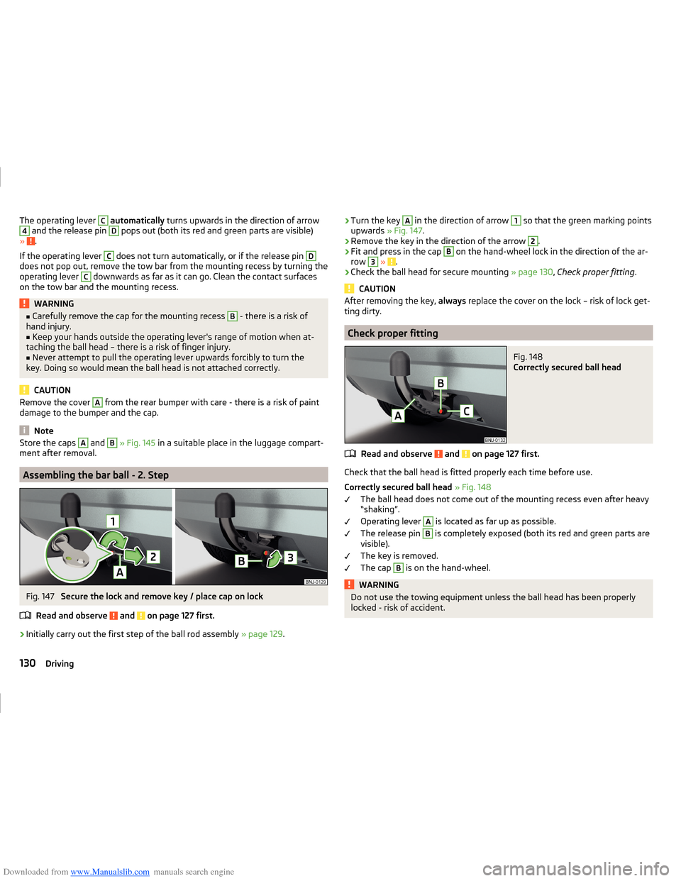
Assembling the bar ball - 2. Step
Fig. 147
Secure the lock and remove key / place cap on lock
Read and observe
and on page 127 first.
›
Initially carry out the first step of the ball rod assembly » page 129.
›Turn the key A in the direction of arrow 1 so that the green marking points
upwards » Fig. 147.›
Remove the key in the direction of the arrow
2
.
›
Fit and press in the cap
B
on the hand-wheel lock in the direction of the ar-
row
3
» .
›
Check the ball head for secure mounting » page 130, Check proper fitting .
CAUTION
After removing the key, always replace the cover on the lock – risk of lock get-
ting dirty.
Check proper fitting
Fig. 148
Correctly secured ball head
Read and observe and on page 127 first.
Check that the ball head is fitted properly each time before use.
Correctly secured ball head » Fig. 148
The ball head does not come out of the mounting recess even after heavy
“shaking”.
Operating lever
A
is located as far up as possible.
The release pin
B
is completely exposed (both its red and green parts are
visible).
The key is removed.
The cap
B
is on the hand-wheel.
WARNINGDo not use the towing equipment unless the ball head has been properly
locked - risk of accident.130Driving
Page 135 of 216
Downloaded from www.Manualslib.com manuals search engine CAUTION■If the operating lever B is held firm and not pushed downwards as far as it
can go, it will go back up after the ball head is removed and will not latch into
the ready position. The ball head then needs to be brought into this position
before the next time it is fitted » page 128, Adjusting the ready position .■
Place the tow bar in the standby position, with the key upwards, and store in
the box - otherwise there is a risk of damage to the key!
■
Do not use excessive force when handling the operating lever (e.g. do not
step on it).
Note
Clean any dirt from the ball head before stowing it away in the box with the
vehicle tool kit.
Accessories
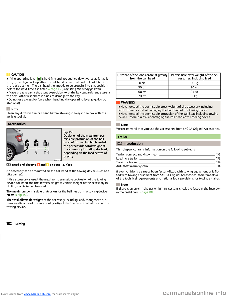
Fig. 152
Depiction of the maximum per-
missible protrusion of the ball
head of the towing hitch and of
the permissible total weight of
the accessory including the load,
depending on the load centre of
gravity
Read and observe and on page 127 first.
An accessory can be mounted on the ball head of the towing device (such as a
bike carrier).
If this accessory is used, the maximum permissible protrusion of the towing
device ball head and the permissible gross vehicle weight of the accessory in-
cluding load is to be observed.
The maximum permissible protrusion for the ball head of the towing device is
70 cm » Fig. 152 .
The total allowable weight of the accessory including load, changes with in-
creasing distance of the centre of gravity of the load from the ball head of the
towing device.
Distance of the load centre of gravity from the ball headPermissible total weight of the ac-cessories, including load0 cm50 kg30 cm50 kg60 cm25 kg70 cm0 kgWARNING■Never exceed the permissible gross weight of the accessory including
load - there is a risk of damaging the ball head of the towing device.■
Never exceed the permissible protrusion of the ball head including towing
device - there is a risk of damaging the ball head of the towing device.
Note
We recommend that you use the accessories from ŠKODA Original Accessories.
Trailer
Introduction
This chapter contains information on the following subjects:
Trailer, connect and disconnect
133
Loading a trailer
133
Towing a trailer
134
Anti-theft alarm system
134
If your vehicle has already been factory-fitted with towing equipment or is fit-
ted with towing equipment from ŠKODA Original Accessories, then it meets all
of the technical requirements and national legal provisions for towing a trailer.
Note
If there is an error in the trailer lighting system, check the fuses in the fuse box
in the dashboard » page 181.132Driving
Page 136 of 216
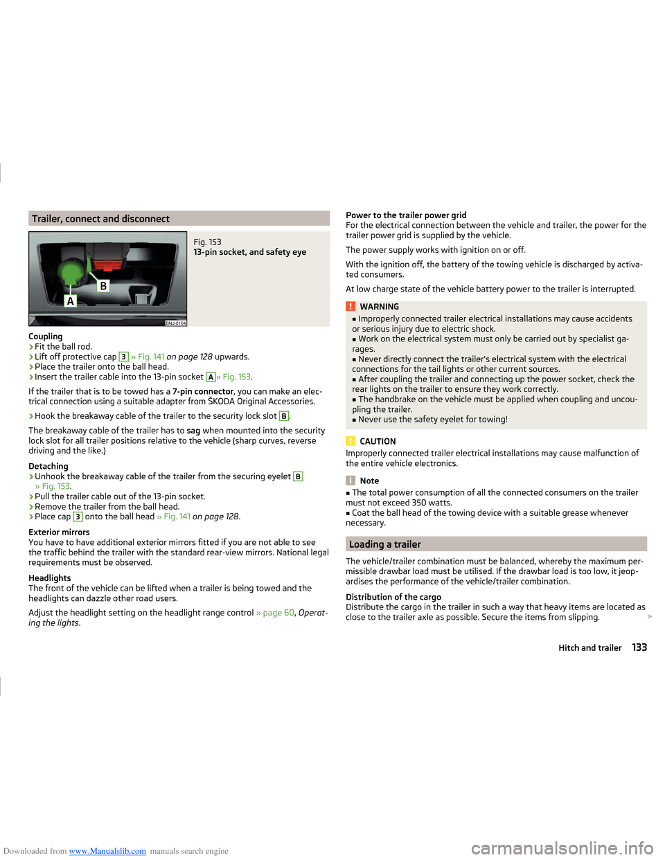
Downloaded from www.Manualslib.com manuals search engine Trailer, connect and disconnectFig. 153
13-pin socket, and safety eye
Coupling
›
Fit the ball rod.
›
Lift off protective cap
3
» Fig. 141 on page 128 upwards.
›
Place the trailer onto the ball head.
›
Insert the trailer cable into the 13-pin socket
A
» Fig. 153.
If the trailer that is to be towed has a 7-pin connector, you can make an elec-
trical connection using a suitable adapter from ŠKODA Original Accessories.
›
Hook the breakaway cable of the trailer to the security lock slot
B
.
The breakaway cable of the trailer has to sag when mounted into the security
lock slot for all trailer positions relative to the vehicle (sharp curves, reverse
driving and the like.)
Detaching
›
Unhook the breakaway cable of the trailer from the securing eyelet
B
» Fig. 153 .
›
Pull the trailer cable out of the 13-pin socket.
›
Remove the trailer from the ball head.
›
Place cap
3
onto the ball head » Fig. 141 on page 128 .
Exterior mirrors
You have to have additional exterior mirrors fitted if you are not able to see
the traffic behind the trailer with the standard rear-view mirrors. National legal
requirements must be observed.
Headlights
The front of the vehicle can be lifted when a trailer is being towed and the
headlights can dazzle other road users.
Adjust the headlight setting on the headlight range control » page 60, Operat-
ing the lights .
Power to the trailer power grid
For the electrical connection between the vehicle and trailer, the power for the
trailer power grid is supplied by the vehicle.
The power supply works with ignition on or off.
With the ignition off, the battery of the towing vehicle is discharged by activa-
ted consumers.
At low charge state of the vehicle battery power to the trailer is interrupted.WARNING■ Improperly connected trailer electrical installations may cause accidents
or serious injury due to electric shock.■
Work on the electrical system must only be carried out by specialist ga-
rages.
■
Never directly connect the trailer's electrical system with the electrical
connections for the tail lights or other current sources.
■
After coupling the trailer and connecting up the power socket, check the
rear lights on the trailer to ensure they work correctly.
■
The handbrake on the vehicle must be applied when coupling and uncou-
pling the trailer.
■
Never use the safety eyelet for towing!
CAUTION
Improperly connected trailer electrical installations may cause malfunction of
the entire vehicle electronics.
Note
■ The total power consumption of all the connected consumers on the trailer
must not exceed 350 watts.■
Coat the ball head of the towing device with a suitable grease whenever
necessary.
Loading a trailer
The vehicle/trailer combination must be balanced, whereby the maximum per-
missible drawbar load must be utilised. If the drawbar load is too low, it jeop-
ardises the performance of the vehicle/trailer combination.
Distribution of the cargo
Distribute the cargo in the trailer in such a way that heavy items are located as
close to the trailer axle as possible. Secure the items from slipping.
133Hitch and trailer
Page 137 of 216
Downloaded from www.Manualslib.com manuals search engine The distribution of the weight is very poor if your vehicle is unladen and the
trailer is laden. Maintain a particularly low speed if you cannot avoid driving
with this combination.
Tyre pressure
Correct the tyre inflation pressure on your vehicle for a “full load” » page 161.
Towing capacity and trailer weight
The permissible trailer load must not be exceeded under any circumstances
» page 192 , Technical data .
The details given in the vehicle's technical documentation always take prece-
dence over the details in the Owner's Manual.
The trailer loads specified apply only to altitudes up to 1,000 metres above
mean sea level.
The engine output falls as altitude increases, as does the ability to climb.
Therefore, for every additional 1,000 m in height (or part), the maximum per-
missible towed weight must be reduced by 10 %.
The towed weight comprises the actual weights of the (loaded) towing vehicle and the (loaded) trailer.
The trailer and drawbar load information on the type plate of the towing
equipment are merely test data for the towing equipment. The vehicle-specific
values are detailed in the vehicle documents.WARNING■ Do not exceed the maximum permissible axle and drawbar load and
weight of the trailer - risk of accident and serious injuries!■
An unsecured load can adversely affect stability and driving safety signifi-
cantly - there is a risk of accident!
Towing a trailer
Driving speed
For safety reasons, do not drive faster than 80 km/h when towing a trailer.
Immediately reduce your speed as soon as even the slightest swaying of the
trailer is detected. Never attempt to stop the trailer from “swaying” by acceler-
ating.
Brakes
Apply the brakes in good time! If the trailer is fitted with a trailer brake, apply
the brakes gently at first, then brake firmly. This will avoid brake jolts resulting
from the trailer wheels locking.
On downhill sections shift down a gear in good time to also use the engine as
a brake.
Engine overheating
If the pointer of the coolant temperature gauge reaches the red scale range,
the speed should be reduced immediately.
Stop and switch off the engine if the warning light
illuminates in the instru-
ment cluster display.
The following information must be observed » page 36,
Coolant
.
The coolant temperature can be reduced by switching on the heating.WARNING■ Always drive particularly carefully with the trailer.■Adapt your speed to the conditions of the road surface and to the traffic
situation.
CAUTION
If you tow a trailer frequently, you should also have your vehicle inspected be-
tween service intervals.
Anti-theft alarm system
When the vehicle is locked, the alarm is activated when the electrical connec-
tion to the trailer is interrupted.
Always switch off the anti-theft alarm system before a trailer is coupled or un-
coupled » page 54 .
Conditions for including a trailer in the anti-theft alarm system. The vehicle is factory-fitted with an anti-theft alarm system and towing
equipment.
The trailer is electrically connected to the towing vehicle by means of the
trailer socket.
The electrical system of the vehicle and trailer is functional.
The vehicle is locked with the vehicle key and the anti-theft alarm system
is activated.
134Driving
Page 144 of 216
Downloaded from www.Manualslib.com manuals search engine Jack143Wheels143
Towing device and mounting recess
144
Under-body protection
144
Wiper blades
144
We recommend using care products from ŠKODA Original Accessories that are
available from ŠKODA Partners. The instructions for use on the package must
be observed.
WARNING■ Care products may be harmful to your health if not used according to the
instructions.■
Always keep the automobile care products safe from people who are not
completely independent, e.g. children - there is a danger of poisoning!
■
Protect your hands and arms from sharp-edged metal parts when clean-
ing the underfloor, the inside of the wheel housings or the wheel trims –
risk of cuts!
CAUTION
■ Do not use any insect sponges, kitchen scrubbers or similar cleaning prod-
ucts – there is a risk of damaging the paintwork finish.■
Cleaners containing solvents can damage the material being cleaned.
For the sake of the environment
Used cans of vehicle care product represent hazardous waste that is harmful
to the environment. These must be disposed of in accordance with national
legislation.
Note
Because of the special tools and knowledge required, and to avoid any poten-
tial problems with the cleaning and care of the exterior of your vehicle, we rec-
ommend that cleaning and care of your vehicle be carried out by a ŠKODA
Service Partner.
Vehicle paint work
Read and observe
and on page 141 first.
Preserving the vehicle paintwork
Thorough wax treatment is an effective way of protecting the paintwork from
harmful environmental influences.
The vehicle must be treated with a high-quality hard wax polish at the latest,
when no more drops form on the clean paintwork.
A new layer of a high-quality hard wax polish can be applied to the clean body- work after it has dried thoroughly.
Even if you use a wax preserver regularly we still recommend that you treat
the paintwork of the vehicle at least twice a year with hard wax.
Polishing
Polishing is necessary if the vehicle's paintwork has become unattractive and
if it is no longer possible to achieve a gloss with wax preservatives.
If the polish does not contain any preserving elements, the paint must be trea- ted with a preservative afterwards.
CAUTION
■ Paint damage is to be repaired immediately.■Never apply wax to the windows.■
Mat painted or plastic parts must not be treated with polishing products or
hard waxes.
■
Do not polish the paintwork in a dusty environment - there is a risk of
scratching the paintwork.
■
Do not apply polish to door seals or window guides.
■
If possible, do not apply any polish to body surfaces that come into contact
with door seals and window guides.
Plastic parts
Read and observe
and on page 141 first.
Clean plastic parts with a damp cloth.
If this method does not clean plastic parts completely, use a specific plastic
care product.
CAUTION
Do not use polish on plastic parts.
Rubber seals
Read and observe
and on page 141 first.
All door seals and window guides are factory-treated with a colourless mattvarnish layer against a freezing to painted body parts and against road noise.
141Care and maintenance
Page 147 of 216
Downloaded from www.Manualslib.com manuals search engine Towing device and mounting recessRead and observe
and on page 141 first.
Close the mounting recess with the cap to prevent any ingress of dirt.
In the event of dirt, clean the inner surfaces of the mounting recess and treat with a suitable preservative.
Before hitching a trailer check the ball head and apply a suitable grease where
necessary.
Fit the protective cap when stowing away the ball head to protect the luggage
compartment against dirt.
CAUTION
Apply grease to the inner part of the mounting recess. Make sure you do not
remove any grease.
Under-body protection
Read and observe
and on page 141 first.
The underside of your vehicle is already permanently protected by the factory
against chemical and mechanical influences.
It is not possible to guarantee that the protective coating will not suffer any
damage as the vehicle is driven.
We recommend that you have the protective coating under the body and on
the chassis inspected - preferably before the beginning and at the end of the
cold season.
WARNINGNever use additional underbody protection or anti-corrosion agents for ex-
haust pipes, catalytic converters, diesel particle filters or heat shields.
These substances could ignite when the engine reaches its operating tem-
perature - there is a risk of fire.Wiper blades
Read and observe
and on page 141 first.
Clean the wiper blades regularly with a glass cleaner. The wiper blades shouldbe cleaned with a sponge or cloth if they are heavily soiled by insect residues,
for example.
The wiper blades can become soiled with wax residues after washing in auto-
matic vehicle wash systems for example.
Interior care
Introduction
This chapter contains information on the following subjects:
Natural leather
145
Artificial leather, materials and Alcantara ®
145
Seat covers
146
Safety belts
146
We recommend using care products from ŠKODA Original Accessories that are
available from ŠKODA Partners. The instructions for use on the package must
be observed.
WARNING■ Care products may be harmful to your health if not used according to the
instructions.■
Always keep the automobile care products safe from people who are not
completely independent, e.g. children - there is a danger of poisoning!
■
Air fresheners and scents can be hazardous to heath when the tempera-
ture inside the vehicle is high.
CAUTION
■ Be sure to check clothing for colourfastness to avoid any damage or visible
stains on the material (leather), panels and textiles.■
Remove fresh stains such as those from ball-point pens, ink, lipstick, shoe
polish, etc., from the material (leather), panels and textiles as quickly as possi-
ble.
■
Do not attach scents and air fresheners to the dashboard – risk of damage to
the dash panel.
144General Maintenance
Page 170 of 216
Downloaded from www.Manualslib.com manuals search engine The reflective vest can be stowed in the storage compartment inside the stor-
age compartment of the door A» Fig. 168 .
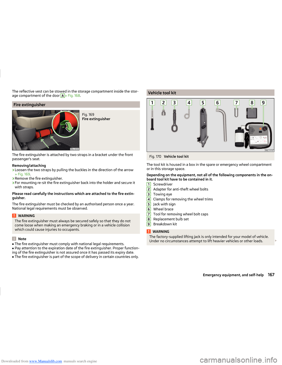
Fire extinguisher
Fig. 169
Fire extinguisher
The fire extinguisher is attached by two straps in a bracket under the front
passenger's seat.
Removing/attaching
›
Loosen the two straps by pulling the buckles in the direction of the arrow
» Fig. 169 .
›
Remove the fire extinguisher.
›
For mounting re-sit the fire extinguisher back into the holder and secure it
with straps.
Please read carefully the instructions which are attached to the fire extin-
guisher.
The fire extinguisher must be checked by an authorised person once a year.
National legal requirements must be observed.
WARNINGThe fire extinguisher must always be secured safely so that they do not
come loose when making an emergency braking or in a vehicle collision
which could cause injuries to occupants.
Note
■ The fire extinguisher must comply with national legal requirements.■Pay attention to the expiration date of the fire extinguisher. Proper function-
ing of the fire extinguisher is not assured once it has passed its expiry date.■
The fire extinguisher is part of the scope of delivery in certain countries only.
Vehicle tool kitFig. 170
Vehicle tool kit
The tool kit is housed in a box in the spare or emergency wheel compartment
or in this storage space.
Depending on the equipment, not all of the following components in the on-
board tool kit have to be contained in it.
Screwdriver
Adapter for anti-theft wheel bolts
Towing eye
Clamps for removing the wheel trims
Jack with sign
Wheel brace
Tool for removing wheel bolt caps
Replacement bulb set
Breakdown kit
WARNINGThe factory-supplied lifting jack is only intended for your model of vehicle.
Under no circumstances attempt to lift heavier vehicles or other loads. 123456789167Emergency equipment, and self-help
Page 171 of 216
Downloaded from www.Manualslib.com manuals search engine CAUTION■Screw the jack back to the starting position before storing in the box with
the tool kit screws.■
Ensure that the vehicle tool kit is safely secured in the boot.
■
Ensure that the box is always secured with the strap.
Note
The declaration of conformity is included with the jack or the log folder.
Changing a wheel
Introduction
This chapter contains information on the following subjects:
Preparation
168
Remove / store wheel
168
Full wheel trim
168
Wheel bolts
169
Anti-theft wheel bolts
169
Loosening/tightening wheel bolts
170
Raising the vehicle
170
Remove the wheel / fix
171
Subsequent steps
171
For your own safety and the safety of the passengers, the following instruc-
tions must be observed before changing a wheel on the road.
Switch on the hazard lights.
The warning triangle must be set up at the prescribed distance - observe
the national legal provisions when doing so.
Park the vehicle as far away as possible from the flow of traffic.
Choose a location with a flat, solid surface.
Have all the occupants get out. The passengers should not stand on the
road (instead they should remain behind a crash barrier, for instance) while
the wheel is being changed.
The national legal requirements must be observed when changing a wheel.
Preparation
Before changing the wheel, the following work should be carried out.
› Switch off the engine.›Select the
first gear or move the selector lever for the automatic gearbox
into position P .›
Apply the handbrake firmly.
›
Uncouple trailer, if attached.
›
Remove the vehicle tool kit » page 167 and the spare wheel from the boot.
Remove / store wheel
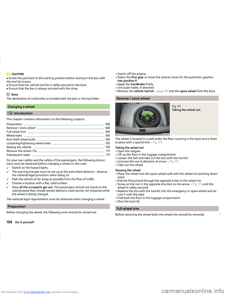
Fig. 171
Taking the wheel out
The wheel is located in a well under the floor covering in the boot and is fixed
in place with a special bolt » Fig. 171.
Taking the wheel out
›
Open the tailgate.
›
Lift up the floor in the luggage compartment.
›
Loosen the belt and take out the box with the tool kit.
›
Unscrew the nut in direction of arrow » Fig. 171.
›
Take out the wheel.
Stowing the wheel
›
Place the wheel into the spare wheel well with the wheel rim pointing down-
ward.
›
Pull the fixing band through the opposite holes in the wheel rim.
›
Screw on the nut in the opposite direction to the arrow » Fig. 171 until the
wheel is safely secured.
›
Replace the box with the tool kit into the emergency or spare wheel and se-
cure it with the tape.
›
Fold back the floor in the luggage compartment.
›
Shut the boot lid.
Full wheel trim
Before removing the wheel bolts the wheel trim should be removed.
168Do-it-yourself
Page 178 of 216
Downloaded from www.Manualslib.com manuals search engine Fig. 179
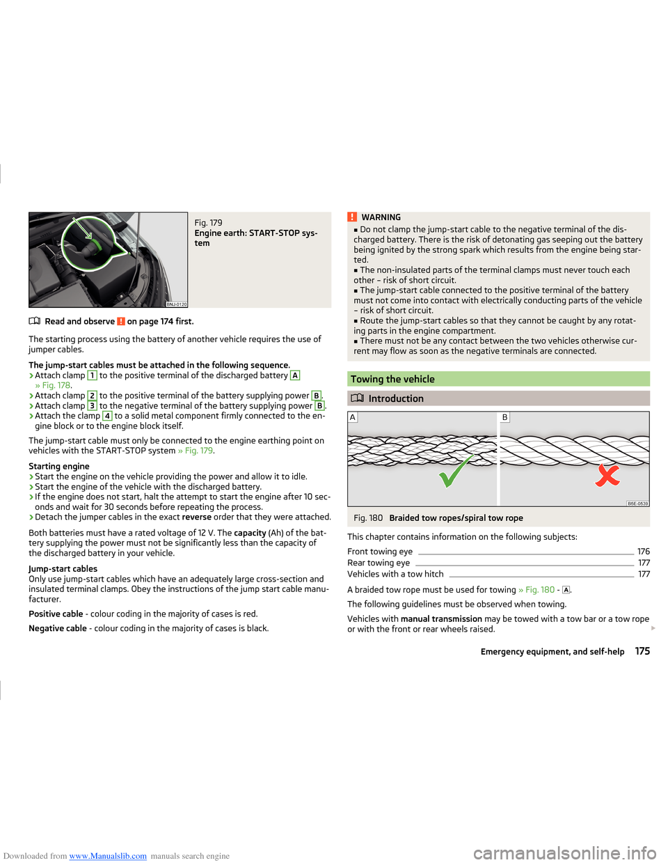
Engine earth: START-STOP sys-
tem
Read and observe on page 174 first.
The starting process using the battery of another vehicle requires the use of
jumper cables.
The jump-start cables must be attached in the following sequence.
›
Attach clamp
1
to the positive terminal of the discharged battery
A
» Fig. 178 .
›
Attach clamp
2
to the positive terminal of the battery supplying power
B
.
›
Attach clamp
3
to the negative terminal of the battery supplying power
B
.
›
Attach the clamp
4
to a solid metal component firmly connected to the en-
gine block or to the engine block itself.
The jump-start cable must only be connected to the engine earthing point on
vehicles with the START-STOP system » Fig. 179.
Starting engine
›
Start the engine on the vehicle providing the power and allow it to idle.
›
Start the engine of the vehicle with the discharged battery.
›
If the engine does not start, halt the attempt to start the engine after 10 sec-
onds and wait for 30 seconds before repeating the process.
›
Detach the jumper cables in the exact reverse order that they were attached.
Both batteries must have a rated voltage of 12 V. The capacity (Ah) of the bat-
tery supplying the power must not be significantly less than the capacity of
the discharged battery in your vehicle.
Jump-start cables
Only use jump-start cables which have an adequately large cross-section and
insulated terminal clamps. Obey the instructions of the jump start cable manu-
facturer.
Positive cable - colour coding in the majority of cases is red.
Negative cable - colour coding in the majority of cases is black.
WARNING■
Do not clamp the jump-start cable to the negative terminal of the dis-
charged battery. There is the risk of detonating gas seeping out the battery
being ignited by the strong spark which results from the engine being star-
ted.■
The non-insulated parts of the terminal clamps must never touch each
other – risk of short circuit.
■
The jump-start cable connected to the positive terminal of the battery
must not come into contact with electrically conducting parts of the vehicle
– risk of short circuit.
■
Route the jump-start cables so that they cannot be caught by any rotat-
ing parts in the engine compartment.
■
There must not be any contact between the two vehicles otherwise cur-
rent may flow as soon as the negative terminals are connected.
Towing the vehicle
Introduction
Fig. 180
Braided tow ropes/spiral tow rope
This chapter contains information on the following subjects:
Front towing eye
176
Rear towing eye
177
Vehicles with a tow hitch
177
A braided tow rope must be used for towing » Fig. 180 -
.
The following guidelines must be observed when towing.
Vehicles with manual transmission may be towed with a tow bar or a tow rope
or with the front or rear wheels raised.
175Emergency equipment, and self-help
Page 179 of 216
Downloaded from www.Manualslib.com manuals search engine Vehicles with automatic transmission may be towed with a tow bar or a tow
rope or with the front wheels raised. If the vehicle is raised at rear, the auto-
matic gearbox is damaged!
Driver of the tow vehicle›
Engage the clutch gently when starting off or depress the accelerator partic-
ularly gently if the vehicle is fitted with an automatic gearbox.
›
Only then, approach correctly when the rope is taut.
The maximum towing speed is 50 km/h.
Driver of the towed vehicle
›
Switch on the ignition so that the steering wheel is not locked and so that
the turn signal lights, windscreen wipers and windscreen washer system can
be used.
›
Take the vehicle out of gear or move the selector lever into position N if the
vehicle is fitted with an automatic gearbox.
Please note that the brake servo unit and power steering only operate if the
engine is running. If the engine is not running, significantly more physical force
is required to depress the brake pedal and steer the vehicle.
If using a tow rope, ensure that it is always kept taught.
Both drivers should be familiar with the potential issues of towing a vehicle.
Unskilled drivers should not attempt to tow another vehicle or to be towed.
The vehicle must be transported on a special breakdown vehicle or trailer if it
is not possible to tow the vehicle in the way described or if the towing dis-
tance is greater than 50 km.
WARNING■ When towing, respect the national legal provisions, especially those
which relate to the identification of the towing vehicle and the vehicle be-
ing towed.■
Exercise increased caution when towing.
■
Spiral tow ropes must not be used for towing » Fig. 180 -
, the towing
eye may unscrew out of the vehicle - risk of accident.
■
The tow rope should not be twisted - risk of accident.
CAUTION■ Do not start engine by towing - there is a risk of damaging the engine parts.
The battery from another vehicle can be used as a jump-start aid » page 174,
Jump-starting .■
If the gearbox no longer contains any oil because of a defect, your vehicle
must only be towed with the drive wheels raised clear of the ground or on a
special breakdown vehicle or trailer.
■
To protect both vehicles when tow-starting or towing, the tow rope should
be elastic. Thus one should only use plastic fibre rope or a rope made out of a
similarly elastic material.
■
There is always a risk of excessive stresses and damage resulting at the
points to which you attach the tow rope or tow bar when you attempt to tow a
vehicle which is not standing on a paved road.
■
Attach the tow rope or the tow bar to the towing eyes » page 176 or
» page 177 to the detachable ball head of the towing equipment » page 127 .
Note
We recommend using a tow rope from ŠKODA Original Accessories available
from a ŠKODA Partner.
Front towing eye
Fig. 181
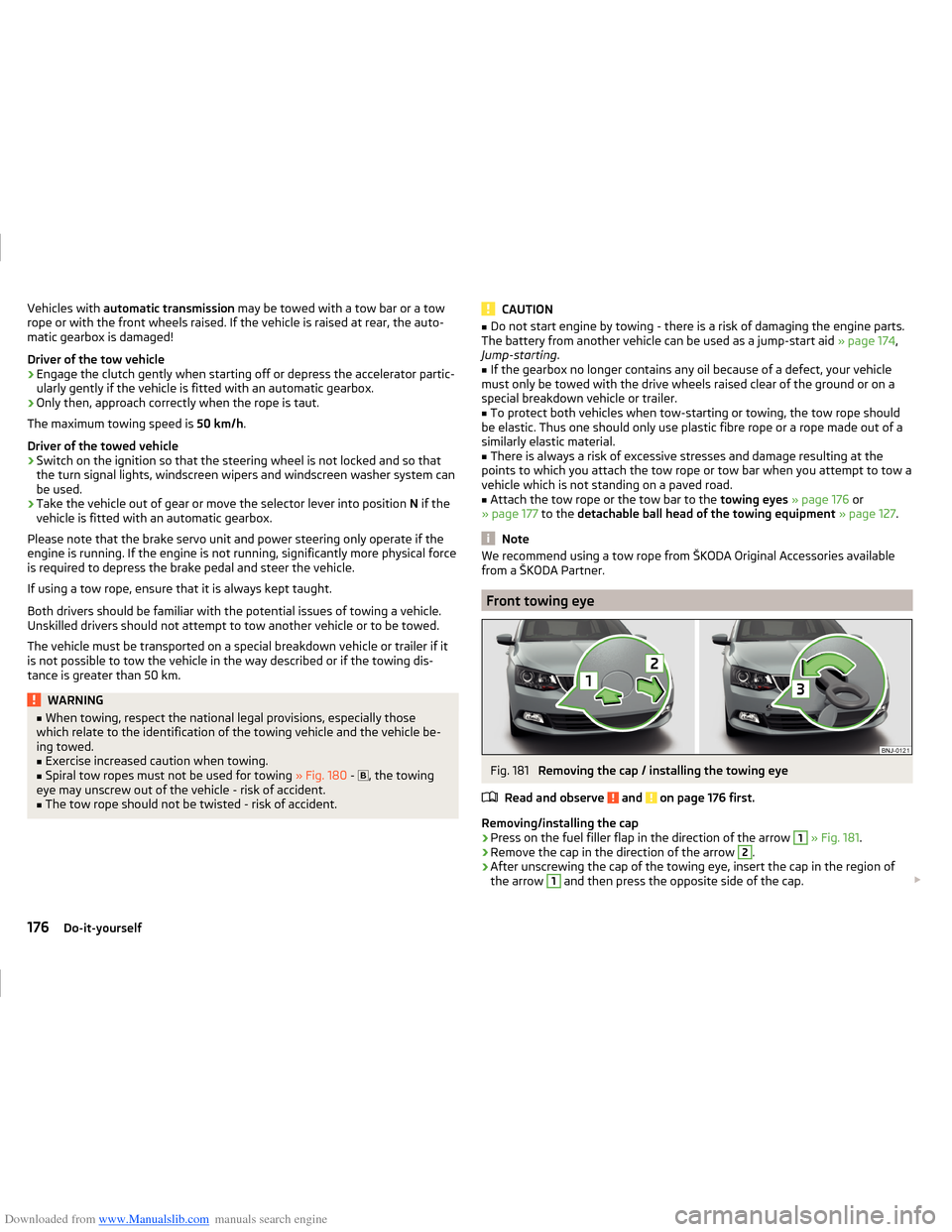
Removing the cap / installing the towing eye
Read and observe
and on page 176 first.
Removing/installing the cap
›
Press on the fuel filler flap in the direction of the arrow
1
» Fig. 181 .
›
Remove the cap in the direction of the arrow
2
.
›
After unscrewing the cap of the towing eye, insert the cap in the region of
the arrow
1
and then press the opposite side of the cap.
176Do-it-yourself