stop start SKODA FABIA 2014 3.G / NJ Operating Instruction Manual
[x] Cancel search | Manufacturer: SKODA, Model Year: 2014, Model line: FABIA, Model: SKODA FABIA 2014 3.G / NJPages: 216, PDF Size: 30.9 MB
Page 115 of 216
Downloaded from www.Manualslib.com manuals search engine Reducing idling
If the vehicle is fitted with the START - STOP system there is an automatic re-
duction of the idling. If the engine is stopped on vehicles without START-STOP
system, such as when waiting in a traffic jam, the fuel economy is already
greater after 30 - 40 s than the fuel quantity which is required for engine re-
start.
Avoid short distances
When driving a short distance of less than about 4 km, the engine cannot
reach its operating temperature. As long as the engine has not reached oper-
ating temperature, the fuel consumption is significantly higher than with the
engine hot.
Pay attention to the correct tyre inflation pressure being maintained
Further information » page 161.
Avoid unnecessary ballast
Per 100 kg of weight, consumption increases by about 0.3 l/100 km. At a speed of 100 - 120 km/h, a vehicle fitted with a roof rack cross member without a load
will use about 10 % more fuel than normal due to the increased aerodynamic
drag.
Saving electricity
Electrical consumers (e.g. seat heating, air conditioning and the like) should
only be turned on for as long as necessary.
Use the cooling system economically
The air conditioning system compressor uses power from the engine when in
cooling mode, which will affect the fuel consumption.
It recommended to open the windows or the doors of a vehicle for which the
interior has been strongly heated through the effect of direct sunlight in order
to allow the heated air to escape.
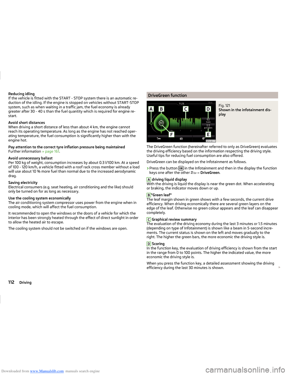
The cooling system should not be switched on if the windows are open.DriveGreen functionFig. 121
Shown in the infotainment dis-
play
The DriveGreen function (hereinafter referred to only as DriveGreen) evaluates
the driving efficiency based on the information respecting the driving style.
Useful tips for reducing fuel consumption are also offered.
DriveGreen can be displayed on the Infotainment as follows.
›
Press the button in the Infotainment and then in the display the function
keys one after the other →
DriveGreen .
A
driving liquid display
With the driving is liquid the display is near the green dot. When accelerating
or braking, the indicator moves down or up.
B
“Green leaf”
The leaf margin shown in green shows with a few seconds, the current drive
efficiency. When driving economically there are several green layers on the
edge of the leaf. Otherwise no green colour appears and the leaf can disappear
completely.
C
Graphical review summary
The evaluation of the driving economy during the last 3 minutes or 1.5 minutes
(depending on type of Infotainment) is shown like a beam in 5-second incre-
ments. The current status is shown on the left and moves gradually to the
right. The higher the green bars, the more economic the driving style is.
D
Scoring
In the function key, the evaluation of driving efficiency is shown from the start
in the range from 0 to 100 points. The higher the indicated value, the more
economic the driving style is.
When you press the function key, a detailed assessment showing the driving
efficiency during the last 30 minutes is shown.
112Driving
Page 117 of 216
Downloaded from www.Manualslib.com manuals search engine ›Therefore, always determine the depth of the water before driving through
water.
The water level must not reach above the web of the lower sill » Fig. 122.›
Do not drive any faster than at a walking speed.
At a higher speed, a water wave can form in front of the vehicle, which can
cause water to penetrate into the engine's air intake system or other parts of
the vehicle.
›
Never stop in the water, do not reverse and do not switch the engine off.
CAUTION
■ Should water penetrate into the intake system of the engine, there is a risk
of serious damage to the engine parts!■
When driving through water, some vehicle parts such as chassis, electrics or
transmissions may be severely damaged.
■
Oncoming vehicles can generate water waves which can exceed the permis-
sible water level for your vehicle.
■
Potholes, mud or rocks can be hidden under the water, making it difficult or
impossible to drive through water.
■
Do not drive through salt water, as the salt can cause corrosion. A vehicle
coming into contact with salt water is to be thoroughly rinsed with fresh wa-
ter.
Assist systems
Braking and stabilisation systems
Introduction
This chapter contains information on the following subjects:
Stability Control (ESC)
114
Anti-lock braking system (ABS)
115
Traction control (TCS)
115
Electronic differential lock (EDL and XDS)
115
Brake Assist (HBA)
115
Hill Start Assist (HHC)
116
Multi collision brake (MCB)
116
This chapter describes the functions of the brake and stabilization systems.
The error display is in Chapter » page 31, Warning lights .
The brake and stabilization systems are automatically activated each time the
ignition is switched on, unless otherwise indicated.
WARNING■ A lack of fuel can cause irregular engine running or cause the engine to
shut down. The brake assist systems could then fail to function – risk of ac-
cident!■
The increased safety provided by the brake assist systems must not
tempt you to take safety risks – risk of accident!
■
Adjust the speed and driving style to the current visibility, weather, road
and traffic conditions.
Stability Control (ESC)
Read and observe
on page 114 first.
The ESC improves vehicle stability in dynamic driving situations, such as whenthe vehicle starts to skid.
The ESC monitors whether the desired direction of the current vehicle motion
is occurring. In case of any deviation (e.g. oversteer), the ESC automatically
brakes individual wheels to maintain the desired direction.
114Driving
Page 127 of 216
Downloaded from www.Manualslib.com manuals search engine Automatic Braking
If the driver fails to respond to the acute warning, the system starts to apply
the brakes automatically with increasing stopping power in several stages.
Brake assist
If the driver brakes inadequate with an impending collision, the system auto-
matically increases braking force.
The braking assistance only occurs as long as the brake pedal is being firmly
pressed down.
Note
■ If an automatic brake intervention is triggered by the system, the pressure in
the brake system increases and the brake pedal cannot be operated with the
normal pedal stroke.■
The automatic braking interventions can be cancelled by pressing the accel-
erator pedal or by steering intervention.
Disable / enable
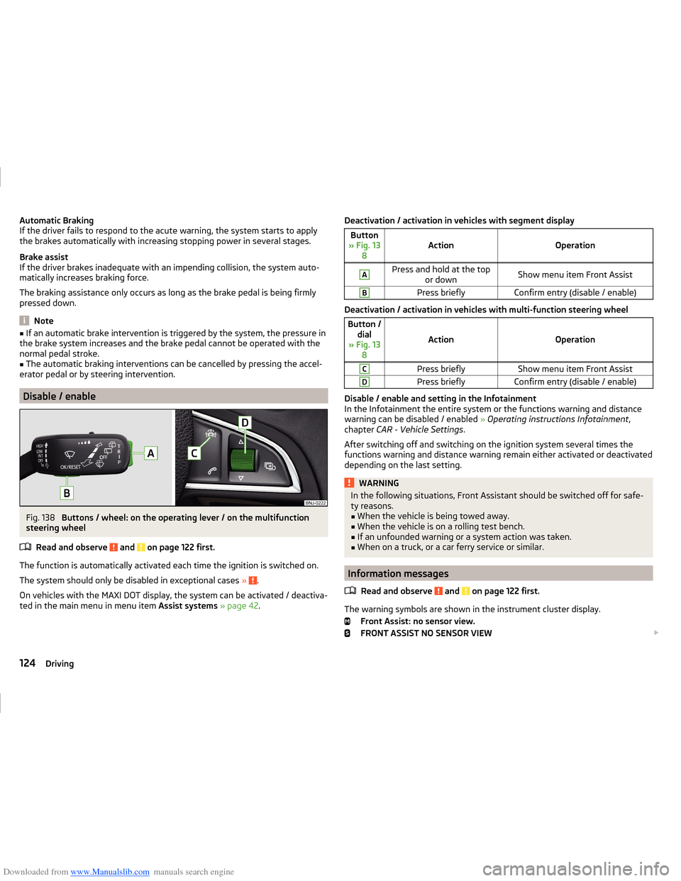
Fig. 138
Buttons / wheel: on the operating lever / on the multifunction
steering wheel
Read and observe
and on page 122 first.
The function is automatically activated each time the ignition is switched on.
The system should only be disabled in exceptional cases »
.
On vehicles with the MAXI DOT display, the system can be activated / deactiva-
ted in the main menu in menu item Assist systems » page 42 .
Deactivation / activation in vehicles with segment displayButton
» Fig. 13 8ActionOperation
APress and hold at the top or downShow menu item Front AssistBPress brieflyConfirm entry (disable / enable)
Deactivation / activation in vehicles with multi-function steering wheel
Button /dial
» Fig. 13 8
ActionOperation
CPress brieflyShow menu item Front AssistDPress brieflyConfirm entry (disable / enable)
Disable / enable and setting in the Infotainment
In the Infotainment the entire system or the functions warning and distance warning can be disabled / enabled » Operating instructions Infotainment ,
chapter CAR - Vehicle Settings .
After switching off and switching on the ignition system several times the
functions warning and distance warning remain either activated or deactivated
depending on the last setting.
WARNINGIn the following situations, Front Assistant should be switched off for safe-
ty reasons.■
When the vehicle is being towed away.
■
When the vehicle is on a rolling test bench.
■
If an unfounded warning or a system action was taken.
■
When on a truck, or a car ferry service or similar.
Information messages
Read and observe
and on page 122 first.
The warning symbols are shown in the instrument cluster display. Front Assist: no sensor view.
FRONT ASSIST NO SENSOR VIEW
124Driving
Page 128 of 216
Downloaded from www.Manualslib.com manuals search engine The sensor is soiled or covered.
Stop the car, switch off the engine and clean the sensor or eliminate the dis-
turbance causing the lack of visibility » Fig. 135 on page 122 .
If after engine start the message persists, then the help of a professional or-
ganisation is required.
Front Assist not available.
FRONT ASSIST NOT AVAILABLE
The system is not available for an unknown reason.
Stop the vehicle, switch off the engine and then start it again.
If after engine start the message persists, then the help of a professional or- ganisation is required.
Fatigue detection
Introduction
This chapter contains information on the following subjects:
Function
125
Information messages
125
The fatigue detection system (hereinafter referred to only as system) recom-
mends the driver taking a break from driving when, because of the driver's
steering behaviour, driver fatigue can be detected.
WARNING■ For the driving ability is always the driver's responsibility. Never drive if
you feel tired.■
The system may not detect all cases where a break is needed.
■
Therefore, take regular, sufficient breaks during long trips.
■
There will be no system warning during the so-called micro-sleep.
Note
■ In some situations, the system may evaluate the driving incorrectly and thus
mistakenly recommend a break (e.g. sporty driving, adverse weather condi-
tions or poor road conditions).■
The system is designed primarily for use on motorways.
Function
Read and observe
on page 125 first.
From the start of the journey, the system evaluates steering behaviour. If,
while driving, there have been changes in the steering behaviours that are
evaluated by the system as indicating possible fatigue, a break recommenda-
tion is issued.
The system evaluates steering behaviour and recommends a break at speeds
of 65 - 200 km/h.
The system detects a break from driving when one of the following condi-
tions is met.
› The vehicle is stopped and the ignition switched off.
› The vehicle is stopped, the seat belt removed and the driver's door opened.
› The vehicle is stopped for more than 15 minutes.
If none of these conditions are met or if the driving style is not changed, the
system recommends a driving break again after 15 minutes.
The system can be activated or deactivated in the Infotainment » Operating
instructions Infotainment , chapter CAR - vehicle settings .
Information messages
Read and observe
on page 125 first.
The icon appears and the following message for a few seconds in the display
of the instrument cluster and the following message.
Driver alert. Take a break!
DRIVER ALERT TAKE A BREAK
An audible signal is also emitted.
Tyre pressure monitoring
Introduction
This chapter contains information on the following subjects:
Save tyre pressure values
126
Save tyre pressure values and infotainment display
126
Save tyre pressure values by pressing a button
127
125Assist systems
Page 153 of 216
Downloaded from www.Manualslib.com manuals search engine WARNINGWhen working in the engine compartment, injuries, scalding, accident or
fire hazards may arise. For this reason, it is essential to comply with the
warning instructions stated below and with the generally applicable rules
of safety. The engine compartment of your car is a hazardous area.WARNINGInstructions before beginning work in the engine compartment■Turn off the engine and remove the ignition key.■
Firmly apply the handbrake.
■
For vehicles with manual transmission the lever into the neutral position.
■
On vehicles with automatic transmission, shift the selector lever into the
P position.
■
Allow the engine to cool.
■
Never open the bonnet if you can see steam or coolant flowing out of the
engine compartment – there is a risk of scalding. Wait until the steam or
coolant has stopped escaping.
WARNINGInformation for working in the engine room■Keep all people, especially children, away from the engine compartment.■
Never touch the radiator fan while the engine is still warm. The fan might
suddenly start running!
■
Do not touch any hot engine parts – there is a risk of burns.
WARNINGInformation for working in the engine compartment with the engine run-
ning■
Pay particular attention to moving engine parts, e.g. V-ribbed belt, gener-
ator, radiator fan - danger to life!
■
Never touch the electric wiring on the ignition system.
■
Avoid short circuits in the electrical system, particularly on the vehicle's
battery.
■
Always make sure that no jewellery, loose clothing or long hair can get
caught in rotating engine parts – there is a risk of death. Always remove
any jewellery, tie back long hair and wear tight fitting clothing before com-
pleting any work.
WARNINGInformation for working on the fuel system or the electrical system■Always disconnect the vehicle battery from the electrical system.■
Do not smoke.
■
Never work near open flames.
■
Always have a functioning fire extinguisher nearby.
WARNING■ Read the information and warning instructions on the fluid containers.■Keep the working fluids in sealed original containers and safe from peo-
ple who are not completely independent, e.g. children.■
Never spill operating fluids over the hot engine - risk of fire.
■
If you wish to work under the vehicle, you must secure the vehicle against
rolling away and support it with suitable axle stands: the car jack is not suf-
ficient for this – there is a risk of injury.
CAUTION
Always top up using the correct specification of fluids. This may result in major
operating problems and also vehicle damage!
For the sake of the environment
In view of the requirements for the environmentally friendly disposal of fluids and the special tools and knowledge required for such work, we recommend
that fluids be changed by a specialist garage.
Note
■ If there is anything you are not sure about concerning fluids, please consult a
specialist garage.■
Fluids with the proper specifications can be purchased from the ŠKODA Origi-
nal Accessories or from the ŠKODA Genuine Parts ranges.
150General Maintenance
Page 161 of 216
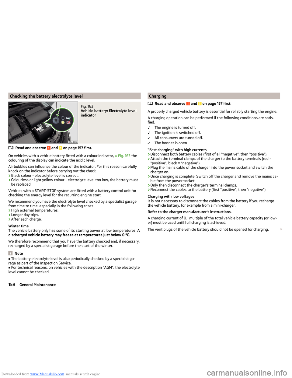
Downloaded from www.Manualslib.com manuals search engine Checking the battery electrolyte levelFig. 163
Vehicle battery: Electrolyte level
indicator
Read and observe and on page 157 first.
On vehicles with a vehicle battery fitted with a colour indicator, » Fig. 163 the
colouring of the display can indicate the acidic level.
Air bubbles can influence the colour of the indicator. For this reason carefully knock on the indicator before carrying out the check.
› Black colour - electrolyte level is correct.
› Colourless or light yellow colour - electrolyte level too low, the battery must
be replaced.
Vehicles with a START-STOP system are fitted with a battery control unit for
checking the energy level for the recurring engine start.
We recommend you have the electrolyte level checked by a specialist garage from time to time, especially in the following cases.
› High external temperatures.
› Longer day trips.
› After each charge.
Winter time
The vehicle battery only has some of its starting power at low temperatures. A
discharged vehicle battery may freeze at temperatures just below 0 °C .
We therefore recommend that you have the battery checked and, if necessary,
recharged by a specialist garage before the start of the winter.
Note
■ The battery electrolyte level is also periodically checked by a specialist ga-
rage as part of the Inspection Service.■
For technical reasons, on vehicles with the description “AGM”, the electrolyte
level cannot be checked.
Charging
Read and observe
and on page 157 first.
A properly charged vehicle battery is essential for reliably starting the engine.A charging operation can be performed if the following conditions are satis-
fied.
The engine is turned off.
The ignition is switched off.
All consumers are turned off.
The bonnet is open.
“Fast charging” with high currents
›
Disconnect both battery cables (first of all “negative”, then “positive”).
›
Attach the terminal clamps of the charger to the battery terminals (red =
“positive”, black = “negative”).
›
Plug the mains cable of the charger into the power socket and switch the
charger on.
›
Once charging is complete: Switch off the charger and remove the mains ca-
ble from the power socket.
›
Only then disconnect the charger's terminal clamps.
›
Reconnect the cables to the battery (first “positive”, then “negative”).
Charging with low voltages
It is not necessary to disconnect the cables from the battery if you recharge
the vehicle battery, for example from a mini-charger.
Refer to the charger manufacturer's instructions .
A charging current of 0.1 multiple of the total vehicle battery capacity (or low-
er) must be used until full charging is achieved.
The vent plugs of the vehicle battery should not be opened for charging.
158General Maintenance
Page 162 of 216
Downloaded from www.Manualslib.com manuals search engine WARNING■When you charge a battery, hydrogen is released, and a highly explosive
gas mixture is also produced. An explosion can be caused through sparkling
over during unclamping or loosening of the cable plug while the ignition is
on.■
Creating a bridge between the poles on the battery (e.g. with metal ob-
jects - cables) creates a short circuit - risk of damage to the battery, explo-
sion and burning of the battery, jets of acid spurting out.
■
Avoid creating sparks when working with cables and electrical devices.
Strong sparking represents a risk of injury.
■
Before carrying out any work on the electrical system, switch off the en-
gine, the ignition and all electrical consumers and disconnect the negative
terminal
.
■
“Quick-charging” the vehicle battery is dangerous and requires a special
charger and specialist knowledge.
■
We therefore recommend that vehicle batteries be “rapidly charged” by a
specialist garage.
CAUTION
On vehicles with the START/STOP system or additional heating (auxiliary heat-
ing), the pole terminal of the charger must not be connected directly to the
negative terminal of the vehicle battery, but only to the engine earth
» page 174 .
Replacing
Read and observe
and on page 157 first.
The new vehicle battery must have the same capacity, voltage, current and thesame size as the original battery. Suitable vehicle battery types can be pur-
chased from a specialist garage.
We recommend that the battery is replaced by a specialist garage, where the
new vehicle battery will be installed properly and the original battery will be
disposed of in accordance with national regulations.
Disconnecting or reconnecting
Read and observe
and on page 157 first.
Disconnecting
›
Switch off the ignition.
›First, disconnect the negative terminal
first, then the positive terminal
of the battery.
Connecting›
First, connect the positive
first, then the negative
battery terminal.
After disconnecting and re-connecting the vehicle battery, the following func-
tions or devices are partially or completely inoperative.
Function / deviceOperating measureElectric windows» page 59RadioEnter code » operating instruc-
tions for the Infotainment dis-
play radioTime settings» page 31
CAUTION
■ Disconnect the vehicle battery only with the ignition turned off - there is a
risk of damaging the electrical system of the vehicle.■
Under no circumstances must the battery cables be connected incorrectly –
risk of a cable fire.
Note
■ After disconnecting and re-connecting the vehicle battery, we recommend
having the vehicle checked by a specialist to ensure that the full functionality
of all electrical systems is guaranteed.■
The data of the multi-function display will be reset.
Automatic load deactivation
Read and observe
and on page 157 first.
The vehicle voltage control unit automatically prevents the battery from dis-
charging when the battery is subjected to heavy loads. This may be noticed
from the following.
› The idling speed is raised to allow the generator to deliver more electricity to
the electrical system.
› Where appropriate large convenience consumers, e.g. seat heaters, rear win-
dow heaters, have their power limited or shut off completely if necessary.
159Inspecting and replenishing
Page 178 of 216
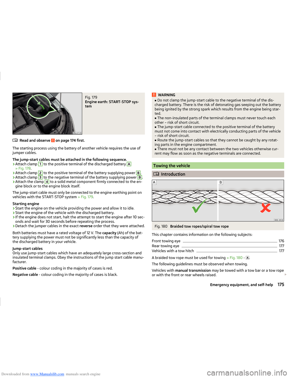
Downloaded from www.Manualslib.com manuals search engine Fig. 179
Engine earth: START-STOP sys-
tem
Read and observe on page 174 first.
The starting process using the battery of another vehicle requires the use of
jumper cables.
The jump-start cables must be attached in the following sequence.
›
Attach clamp
1
to the positive terminal of the discharged battery
A
» Fig. 178 .
›
Attach clamp
2
to the positive terminal of the battery supplying power
B
.
›
Attach clamp
3
to the negative terminal of the battery supplying power
B
.
›
Attach the clamp
4
to a solid metal component firmly connected to the en-
gine block or to the engine block itself.
The jump-start cable must only be connected to the engine earthing point on
vehicles with the START-STOP system » Fig. 179.
Starting engine
›
Start the engine on the vehicle providing the power and allow it to idle.
›
Start the engine of the vehicle with the discharged battery.
›
If the engine does not start, halt the attempt to start the engine after 10 sec-
onds and wait for 30 seconds before repeating the process.
›
Detach the jumper cables in the exact reverse order that they were attached.
Both batteries must have a rated voltage of 12 V. The capacity (Ah) of the bat-
tery supplying the power must not be significantly less than the capacity of
the discharged battery in your vehicle.
Jump-start cables
Only use jump-start cables which have an adequately large cross-section and
insulated terminal clamps. Obey the instructions of the jump start cable manu-
facturer.
Positive cable - colour coding in the majority of cases is red.
Negative cable - colour coding in the majority of cases is black.
WARNING■
Do not clamp the jump-start cable to the negative terminal of the dis-
charged battery. There is the risk of detonating gas seeping out the battery
being ignited by the strong spark which results from the engine being star-
ted.■
The non-insulated parts of the terminal clamps must never touch each
other – risk of short circuit.
■
The jump-start cable connected to the positive terminal of the battery
must not come into contact with electrically conducting parts of the vehicle
– risk of short circuit.
■
Route the jump-start cables so that they cannot be caught by any rotat-
ing parts in the engine compartment.
■
There must not be any contact between the two vehicles otherwise cur-
rent may flow as soon as the negative terminals are connected.
Towing the vehicle
Introduction
Fig. 180
Braided tow ropes/spiral tow rope
This chapter contains information on the following subjects:
Front towing eye
176
Rear towing eye
177
Vehicles with a tow hitch
177
A braided tow rope must be used for towing » Fig. 180 -
.
The following guidelines must be observed when towing.
Vehicles with manual transmission may be towed with a tow bar or a tow rope
or with the front or rear wheels raised.
175Emergency equipment, and self-help
Page 207 of 216
Downloaded from www.Manualslib.com manuals search engine Heating94
Control elements96
Exterior mirrors69
Seats71
HHC116
Hill Start Assist (HHC)116
Hitch127
Drawback load127
Hooks85
Horn26
I
Ice scrapers
142
Ignition lock101
Immobilizer100
Individual settings Locking
52
Unlocking52
Inertia reel13
Information system39
Compass point display45
Door warning39
Gear recommendation39
MAXI DOT display42
Multifunction display40
operation40
Service interval display46
Information system operation40
Infotainment4
Instrument cluster27
Auto-check control39
Counter for distance driven30
Display29
Fuel gauge30
Overview28
Revolution counter28
Temperature gauge29
Warning lights31
Interior care144
Natural leather145
interior light Front
64
Interior monitor55
ISOFIX22
J
Jack
167
Maintenance143
Jacking points Raise vehicle
170
Jump-starting174
K
KESSY Locking
51
Unlocking51
Key Locking
50
Start the engine101
Stopping the engine101
Switch off the ignition101
Switch on the ignition101
Unlocking50
L
Lamp failure Warning light
37
Lamps Warning light
37
Leather Natural leather care
145
LEAVING HOME63
Lever Main beam
61
Turn signal61
Levers Windscreen wipers
67
LightCockpit64
COMING HOME / LEAVING HOME63
Fog lights with CORNER function62
Lighting Luggage compartment
83
Lights59
Automatic driving lamp control61
Daylight running60
Fog lights62
Hazard warning light system63
Headlight flasher61
Headlight range adjustment60
Low beam60
Main beam61
parking lights60
Parking lights63
Rear fog light62
Replacing bulbs184
Switching on and off60
Turn signal61
Warning lights31
Locking Individual settings
52
KESSY51
Key50
Remote control50
Locking and unlocking the vehicle from the in- side
53
Locking the door without a locking cylinder Emergency
179
Low beam60
Luggage compartment83
Cover86
Fastening elements84
Fixing nets84
Flexible storage compartment88
Lighting83
Storage compartments under the floor87
unlock manually179
204Index
Page 210 of 216
Downloaded from www.Manualslib.com manuals search engine Rear seat73
Seat backrests72
Seats and headrest70
Secure variable loading floor
90
see Instrument cluster see Instrument cluster
27
Selector lever Refer to Selector lever
109
Selector lever lock Indicator light
35
Service137
Service interval display46
Warning light38
setting Lower position of the variable loading floor
89
Setting31
Seat belt height12
seats and headrests70
Upper position of the variable loading floor89
Settings Interior mirror
68
Setting the31
Side airbag17
SmartGate Connection via the search for a Wi-Fi network
47
Setting48
Wi-Fi direct48
SmartLink see Infotainment
4
Snow chains165
Sockets 12 V
78
Spare change
168
spare wheel change
168
Spare wheel163
Speed control system118
Speed limiter120
Indicator light35
Operation120
Operation description121
Speed symbol see Wheels
164
Spoiler138
Stabilisation system114
Stability Control (ESC)114
Staring engine Jump-starting
174
START-STOP104
Jump-starting174
Manually deactivating/activating the system105
operation104
Warning light38
START-STOP system104
Starter button Problems with the engine start
104
Steering column lock locking102
Steering column lock unlocking102
Switching off the engine103
Switch off the ignition103
Switch on the ignition103
Starting and stopping the engine at the push of the button
102
Starting and stopping the engine using the key 100
Starting engine Jump-starting
174
Starting the engine Starter button
103
START STOP Information messages
105
Start the engine Key
101
Steering column lock locking Starter button
102
Steering column lock unlocking Starter button
102
Steering lock lockingKey100
Steering lock unlocking Key
100
Steering lock (engine start push-button) Warning light
32
Steering wheel correct posture
9
setting9
Stop see Parking
107
Stopping the engine Key
101
Storage74
compartment beneath the front seat81
storage compartment Glasses compartment
80
Storage compartment in the doors
75
in the front arm rest79
in the front centre console76
in the rear centre console82
on the dash panel76
on the front passenger side80
on the side of the front seat75
Storage compartments74
Storage pockets on the front seats81
sun visors66
Sun visors66
Switching lights on and off60
Switching off the engine Starter button
103
Switch off the ignition Key
101
Starter button103
Switch on the ignition Key
101
Starter button103
207Index