reset SKODA FABIA 2014 3.G / NJ Operating Instruction Manual
[x] Cancel search | Manufacturer: SKODA, Model Year: 2014, Model line: FABIA, Model: SKODA FABIA 2014 3.G / NJPages: 216, PDF Size: 30.9 MB
Page 31 of 216
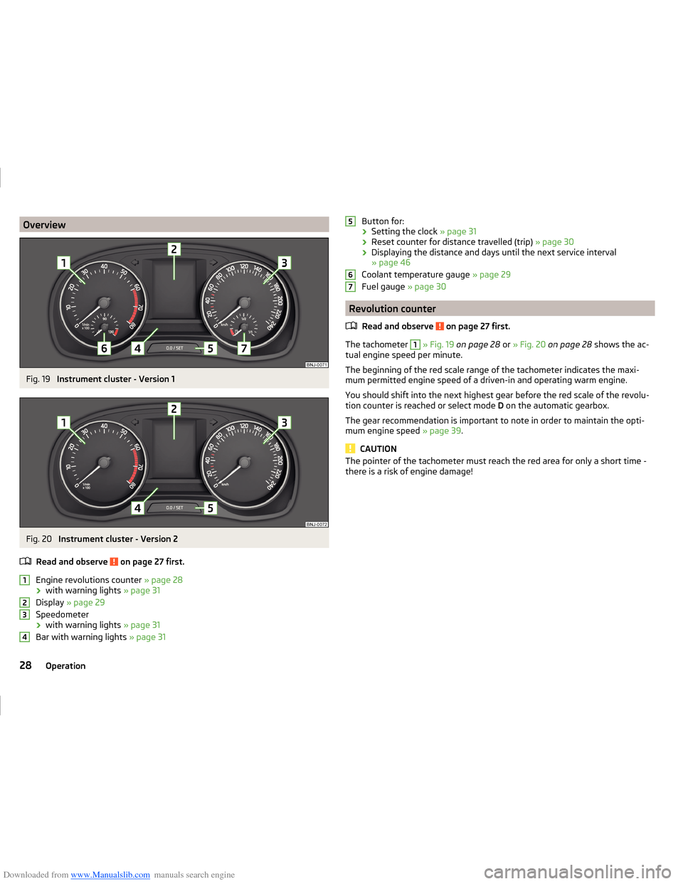
Downloaded from www.Manualslib.com manuals search engine OverviewFig. 19
Instrument cluster - Version 1
Fig. 20
Instrument cluster - Version 2
Read and observe
on page 27 first.
Engine revolutions counter » page 28
› with warning lights
» page 31
Display » page 29
Speedometer › with warning lights
» page 31
Bar with warning lights » page 31
1234Button for:
› Setting the clock
» page 31
› Reset counter for distance travelled (trip)
» page 30
› Displaying the distance and days until the next service interval
» page 46
Coolant temperature gauge » page 29
Fuel gauge » page 30
Revolution counter
Read and observe
on page 27 first.
The tachometer
1
» Fig. 19 on page 28 or » Fig. 20 on page 28 shows the ac-
tual engine speed per minute.
The beginning of the red scale range of the tachometer indicates the maxi-
mum permitted engine speed of a driven-in and operating warm engine.
You should shift into the next highest gear before the red scale of the revolu- tion counter is reached or select mode D on the automatic gearbox.
The gear recommendation is important to note in order to maintain the opti-
mum engine speed » page 39.
CAUTION
The pointer of the tachometer must reach the red area for only a short time -
there is a risk of engine damage!56728Operation
Page 33 of 216
Downloaded from www.Manualslib.com manuals search engine NoteOn vehicles with the multifunction display, the coolant temperature can be
shown on the display by the corresponding driving data entry being selected
» page 40 , Information overview .
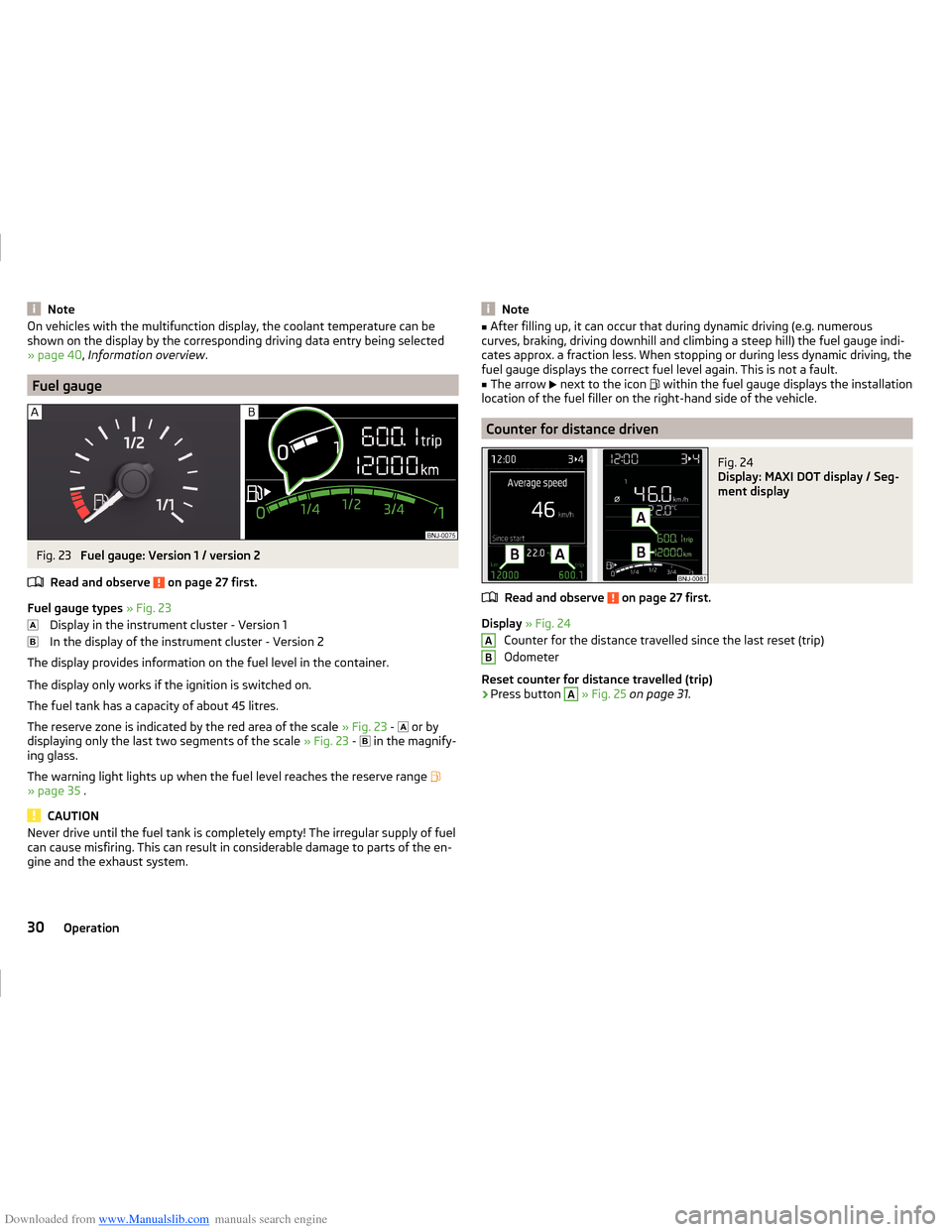
Fuel gauge
Fig. 23
Fuel gauge: Version 1 / version 2
Read and observe
on page 27 first.
Fuel gauge types » Fig. 23
Display in the instrument cluster - Version 1
In the display of the instrument cluster - Version 2
The display provides information on the fuel level in the container.
The display only works if the ignition is switched on.
The fuel tank has a capacity of about 45 litres.
The reserve zone is indicated by the red area of the scale » Fig. 23 -
or by
displaying only the last two segments of the scale » Fig. 23 -
in the magnify-
ing glass.
The warning light lights up when the fuel level reaches the reserve range
» page 35 .
CAUTION
Never drive until the fuel tank is completely empty! The irregular supply of fuel
can cause misfiring. This can result in considerable damage to parts of the en-
gine and the exhaust system.Note■ After filling up, it can occur that during dynamic driving (e.g. numerous
curves, braking, driving downhill and climbing a steep hill) the fuel gauge indi-
cates approx. a fraction less. When stopping or during less dynamic driving, the
fuel gauge displays the correct fuel level again. This is not a fault.■
The arrow
next to the icon
within the fuel gauge displays the installation
location of the fuel filler on the right-hand side of the vehicle.
Counter for distance driven
Fig. 24
Display: MAXI DOT display / Seg-
ment display
Read and observe on page 27 first.
Display » Fig. 24
Counter for the distance travelled since the last reset (trip) Odometer
Reset counter for distance travelled (trip)
›
Press button
A
» Fig. 25 on page 31 .
AB30Operation
Page 45 of 216
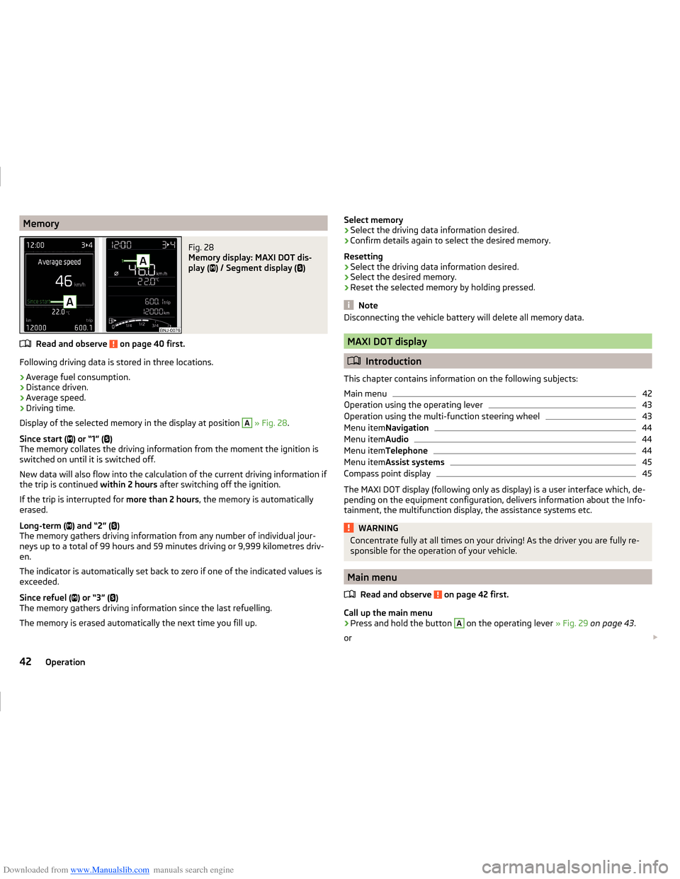
Downloaded from www.Manualslib.com manuals search engine MemoryFig. 28
Memory display: MAXI DOT dis-
play (
) / Segment display (
)
Read and observe on page 40 first.
Following driving data is stored in three locations.
› Average fuel consumption.
› Distance driven.
› Average speed.
› Driving time.
Display of the selected memory in the display at position
A
» Fig. 28 .
Since start ( ) or “1” (
)
The memory collates the driving information from the moment the ignition is
switched on until it is switched off.
New data will also flow into the calculation of the current driving information if
the trip is continued within 2 hours after switching off the ignition.
If the trip is interrupted for more than 2 hours, the memory is automatically
erased.
Long-term ( ) and “2” (
)
The memory gathers driving information from any number of individual jour-
neys up to a total of 99 hours and 59 minutes driving or 9,999 kilometres driv-
en.
The indicator is automatically set back to zero if one of the indicated values is
exceeded.
Since refuel ( ) or “3” (
)
The memory gathers driving information since the last refuelling.
The memory is erased automatically the next time you fill up.
Select memory
› Select the driving data information desired.
› Confirm details again to select the desired memory.
Resetting
› Select the driving data information desired.
› Select the desired memory.
› Reset the selected memory by holding pressed.
Note
Disconnecting the vehicle battery will delete all memory data.
MAXI DOT display
Introduction
This chapter contains information on the following subjects:
Main menu
42
Operation using the operating lever
43
Operation using the multi-function steering wheel
43
Menu item Navigation
44
Menu itemAudio
44
Menu itemTelephone
44
Menu itemAssist systems
45
Compass point display
45
The MAXI DOT display (following only as display) is a user interface which, de-
pending on the equipment configuration, delivers information about the Info-
tainment, the multifunction display, the assistance systems etc.
WARNINGConcentrate fully at all times on your driving! As the driver you are fully re-
sponsible for the operation of your vehicle.
Main menu
Read and observe
on page 42 first.
Call up the main menu
›
Press and hold the button
A
on the operating lever » Fig. 29 on page 43 .
or
42Operation
Page 49 of 216
Downloaded from www.Manualslib.com manuals search engine Service interval display
Introduction
This chapter contains information on the following subjects:
Displaying the distance and days until the next service interval
46
Service messages
46
Resetting the service interval display
46
The service interval display shows the time and mileage to the next service
event.
The information regarding the service intervals can be found in the service
schedule.
Displaying the distance and days until the next service interval
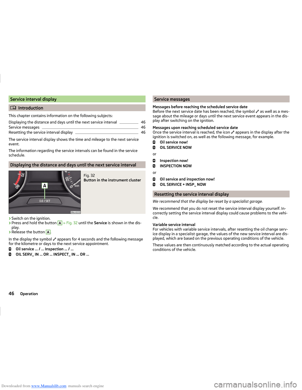
Fig. 32
Button in the instrument cluster
›
Switch on the ignition.
›
Press and hold the button
A
» Fig. 32 until the Service is shown in the dis-
play.
›
Release the button
A
.
In the display the symbol appears for 4 seconds and the following message
for the kilometre or days to the next service appointment.
Oil service … / … Inspection … / …
OIL SERV_ IN … OR … INSPECT_ IN … OR …
Service messages
Messages before reaching the scheduled service date
Before the next service date has been reached, the symbol
as well as a mes-
sage about the mileage or days until the next service event appears in the dis-
play after switching on the ignition.
Messages upon reaching scheduled service date
Once the service interval is reached, the icon
appears in the display after the
ignition is switched on, as well as the following message, for example.
Oil service now!
OIL SERVICE NOW
or Inspection now!
INSPECTION NOW
or Oil service and inspection now!
OIL SERVICE + INSP_ NOW
Resetting the service interval display
We recommend that the display be reset by a specialist garage.
We recommend that you do not reset the service interval display yourself. In-
correctly setting the service interval display could cause problems to the vehi-
cle.
Variable service interval
For vehicles with variable service intervals, after resetting the oil change serv-
ice display in a specialist garage, the values of the new service interval are dis-
played, which are based on the previous operating conditions of the vehicle.
These values are then continuously matched according to the actual operating
conditions of the vehicle.
46Operation
Page 50 of 216
Downloaded from www.Manualslib.com manuals search engine SmartGate
Introduction
This chapter contains information on the following subjects:
Connection to SmartGate using Wi-Fi
47
Connection using Wi-Fi direct to SmartGate
48
SmartGate web interface
48
SmartGate constitutes a system, which transmit certain driving data (such as
fuel consumption, speed or similar) via Wi-Fi and Wi-Fi Direct.
The ŠKODA compatible communications device (e.g. phone, tablet, notebook)
offer the possibility to further transmit the received data.
More information on available applications, a list of compatible communication
devices and on SmartGate, can be found on the ŠKODA Internet pages.
Use the Service App application to update the SmartGate software. You can
fine information on this application on the ŠKODA Internet pages.
WARNING■ The national legal regulations for using mobile communication devices in
a vehicle must be observed.■
Do not fit the equipment or mounts to be connected onto airbag covers
or within the immediate deployment range of the airbags.
■
Never leave a connected device in the deployment area of an airbag, on a
seat, on the dash panel or any another area, from which it can be thrown
during a sudden braking manoeuvre, an accident or a collision - there is a
risk of injury.
CAUTION
ŠKODA accepts no responsibility for any problems caused by incompatibility or
improper functioning of the communication equipment and the applications.Note■ The ŠKODA applications, support communications devices with the Android
operating system version 4.x.x and later and iOS 7.x.x and higher.■
With SmartGate, a device can be connected to two ongoing ŠKODA applica-
tions, possibly two devices, each with a respective current ŠKODA application.
■
If you have forgotten your password for the connection to SmartGate, Smart-
Gate must be reset to factory settings in a specialised workshop.
Connection to SmartGate using Wi-Fi
Read and observe
and on page 47 first.
For a successful connection the following conditions must be met. Wi-Fi is turned on in the device to be connected.
The ignition is switched on.
Connection set-up
›
Can enable the connected device to search for available Wi-Fi networks (see
operating instructions for the connected device).
›
In the menu of the detected networks select “SmartGate_...” 1)
or “DIRECT
SmartGate_...” 1)
.
›
Enter the password (the password is preset at the factory to the complete
Vehicle Identification Number - enter capital letters).
Disconnection
The connection can be switched off in one of the following ways.
› By disconnecting the connected device from SmartGate.
› By turning off the Wi-Fi in the connected device.
› By switching off the ignition for more than 5 s (for vehicles with starter but-
ton - by turning off the engine and opening the driver's door).
Automatic connection
If the communication device once had a connection with SmartGate, then the
connection is automatically restored under the following conditions.
Wi-Fi is turned on in the device to be connected.
The ignition is switched on.
The device to be connected stores the password required for the connec-
tion check.
1)
The last six symbols of the VIN vehicle identification number of your vehicle are displayed at position ....
47Information system
Page 116 of 216
Downloaded from www.Manualslib.com manuals search engine If the trip from the start, takes less than 30 minutes, then the assessment
takes in information from the previous trip (the bars are shown in dark green).E
Average fuel consumption
In the function key, the average fuel consumption from the start is displayed.
When you press the function key a detailed overview of the average fuel con-
sumption during the last 30 minutes is shown.
If the trip from the start, takes less than 30 minutes, then the average fuel
consumption takes in information from the previous trip (the bars are shown in
dark green).
F
Symbols in the display
The display may show the following four symbols, which give information on
the current driving style.
Ecological trip
The current speed has a negative effect on fuel consumption. The driving is not liquid, drive with anticipation.
Recommended gear.
Tips for reducing fuel consumption
When tapping the “Page” the display shows useful tips on how to reduce fuel consumption. These tips can to be helpful to drive more economically.
Note
■ Resetting the single-trip memory “from start” also resets the average con-
sumption E and the driving assessment D.■
With some Infotainment types changing the units for the fuel consumption
indicator causes the resetting of the average fuel consumption values
E
.
Avoiding damage to your vehicle
Introduction
This chapter contains information on the following subjects:
Driving Tips
113
Driving through water
113
This section of the manual contains important information on preventing dam-
age to the vehicle while driving.
Driving Tips
Only drive on such roads and in such terrain, which match the vehicle parame-
ters » page 192 , Technical data as well as your driving skills.
The driver is always responsible for deciding whether the vehicle can handle
travelling in the given terrain.WARNING■ Always adjust your driving to the current terrain and weather conditions.
Excessive speed or incorrect driving manoeuvres can cause damage to the
vehicle and lead to serious injuries.■
Combustible objects such as dry leaves or twigs caught under the base of
the vehicle could ignite on hot vehicle parts - risk of fire!
CAUTION
■ Pay attention to the ground clearance of the vehicle! When driving over ob-
jects which are larger than the ground clearance, the vehicle can get damaged.■
Any objects that get trapped under the vehicle floor must be removed as
soon as possible. These objects can damage the fuel lines, the brake system,
seals and other parts of the vehicle.
■
Drive slowly in unknown terrain and watch out for unexpected obstacles,
such as potholes, rocks, stumps, etc.
■
Check up on confusing sections of unpaved roads before travelling on them
and consider whether such travelling is possible without risk.
Driving through water
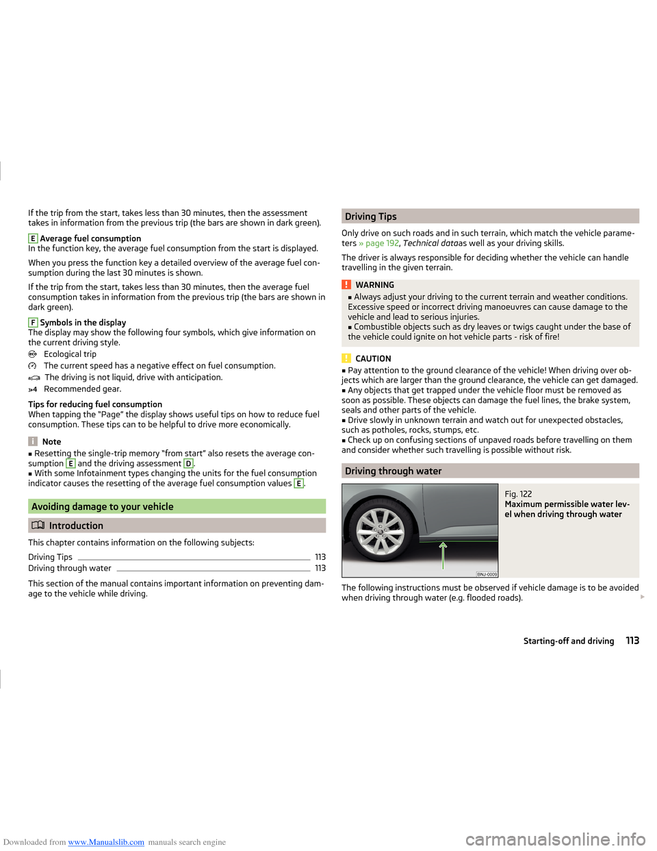
Fig. 122
Maximum permissible water lev-
el when driving through water
The following instructions must be observed if vehicle damage is to be avoided
when driving through water (e.g. flooded roads).
113Starting-off and driving
Page 162 of 216
Downloaded from www.Manualslib.com manuals search engine WARNING■When you charge a battery, hydrogen is released, and a highly explosive
gas mixture is also produced. An explosion can be caused through sparkling
over during unclamping or loosening of the cable plug while the ignition is
on.■
Creating a bridge between the poles on the battery (e.g. with metal ob-
jects - cables) creates a short circuit - risk of damage to the battery, explo-
sion and burning of the battery, jets of acid spurting out.
■
Avoid creating sparks when working with cables and electrical devices.
Strong sparking represents a risk of injury.
■
Before carrying out any work on the electrical system, switch off the en-
gine, the ignition and all electrical consumers and disconnect the negative
terminal
.
■
“Quick-charging” the vehicle battery is dangerous and requires a special
charger and specialist knowledge.
■
We therefore recommend that vehicle batteries be “rapidly charged” by a
specialist garage.
CAUTION
On vehicles with the START/STOP system or additional heating (auxiliary heat-
ing), the pole terminal of the charger must not be connected directly to the
negative terminal of the vehicle battery, but only to the engine earth
» page 174 .
Replacing
Read and observe
and on page 157 first.
The new vehicle battery must have the same capacity, voltage, current and thesame size as the original battery. Suitable vehicle battery types can be pur-
chased from a specialist garage.
We recommend that the battery is replaced by a specialist garage, where the
new vehicle battery will be installed properly and the original battery will be
disposed of in accordance with national regulations.
Disconnecting or reconnecting
Read and observe
and on page 157 first.
Disconnecting
›
Switch off the ignition.
›First, disconnect the negative terminal
first, then the positive terminal
of the battery.
Connecting›
First, connect the positive
first, then the negative
battery terminal.
After disconnecting and re-connecting the vehicle battery, the following func-
tions or devices are partially or completely inoperative.
Function / deviceOperating measureElectric windows» page 59RadioEnter code » operating instruc-
tions for the Infotainment dis-
play radioTime settings» page 31
CAUTION
■ Disconnect the vehicle battery only with the ignition turned off - there is a
risk of damaging the electrical system of the vehicle.■
Under no circumstances must the battery cables be connected incorrectly –
risk of a cable fire.
Note
■ After disconnecting and re-connecting the vehicle battery, we recommend
having the vehicle checked by a specialist to ensure that the full functionality
of all electrical systems is guaranteed.■
The data of the multi-function display will be reset.
Automatic load deactivation
Read and observe
and on page 157 first.
The vehicle voltage control unit automatically prevents the battery from dis-
charging when the battery is subjected to heavy loads. This may be noticed
from the following.
› The idling speed is raised to allow the generator to deliver more electricity to
the electrical system.
› Where appropriate large convenience consumers, e.g. seat heaters, rear win-
dow heaters, have their power limited or shut off completely if necessary.
159Inspecting and replenishing