fuel SKODA FABIA 2014 3.G / NJ Owner's Guide
[x] Cancel search | Manufacturer: SKODA, Model Year: 2014, Model line: FABIA, Model: SKODA FABIA 2014 3.G / NJPages: 216, PDF Size: 30.7 MB
Page 97 of 216
WARNING■The items being transported on the roof rack must be reliably attached –
risk of accident.■
Always secure the load with appropriate and undamaged lashing straps
or tensioning straps.
■
Distribute the load evenly over the roof rack system.
■
When transporting heavy objects or objects which take up a large area on
the roof rack system, handling of the car may change as a result of the dis-
placement of the centre of gravity. The style of driving and speed must
therefore be adapted to circumstances.
■
Avoid abrupt and sudden driving/braking manoeuvres.
■
The permissible roof load, permissible axle loads and gross permissible
weight of the vehicle must not be exceeded under any circumstances – risk
of accident.
CAUTION
■ Only roof racks from the ŠKODA Original Accessories range should be used.■The fitting instructions supplied with the roof luggage rack system must be
observed when handling roof racks.■
Ensure that the boot lid does not hit the roof load when opened.
■
The height of the vehicle changes after mounting a roof luggage rack system
and the load that is secured to it. Compare the vehicle height with available
clearances, such as underpasses and garage doors.
■
Always remove the roof luggage rack system before entering an automated
car wash.
■
Ensure the roof aerial is not impaired by the secured load.
For the sake of the environment
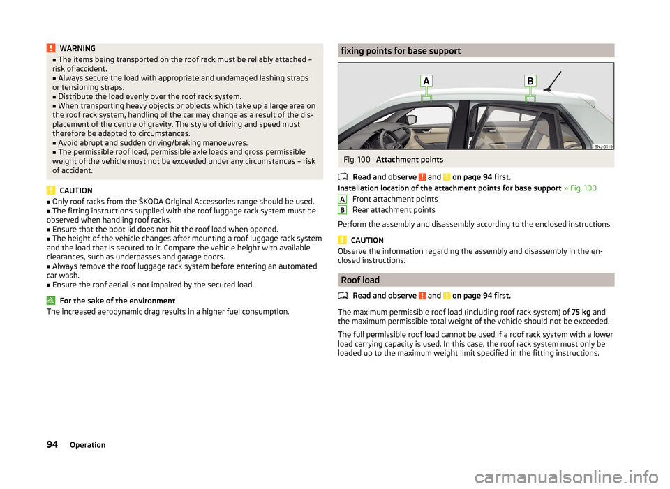
The increased aerodynamic drag results in a higher fuel consumption.fixing points for base supportFig. 100
Attachment points
Read and observe
and on page 94 first.
Installation location of the attachment points for base support » Fig. 100
Front attachment points
Rear attachment points
Perform the assembly and disassembly according to the enclosed instructions.
CAUTION
Observe the information regarding the assembly and disassembly in the en-
closed instructions.
Roof load
Read and observe
and on page 94 first.
The maximum permissible roof load (including roof rack system) of 75 kg and
the maximum permissible total weight of the vehicle should not be exceeded.
The full permissible roof load cannot be used if a roof rack system with a lower
load carrying capacity is used. In this case, the roof rack system must only be
loaded up to the maximum weight limit specified in the fitting instructions.
AB94Operation
Page 102 of 216
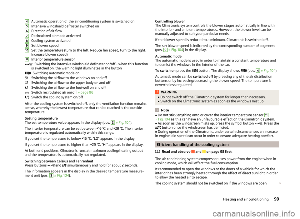
Automatic operation of the air conditioning system is switched on
Intensive windshield defroster switched on
Direction of air flow
Recirculated air mode activated
Cooling system activated
Set blower speed
Set the temperature (turn to the left: Reduce fan speed, turn to the right:
Increase blower speed)
Interior temperature sensor Switching the intensive windshield defroster on/off - when this function
is switched on, the warning light illuminates in the button
Switching automatic mode on
Switching the airflow to the windows on and off
Switching the airflow to the upper body on and off
Switching the airflow to the footwell on and off
Switch recirculated air on/off » page 96
Switch the cooling system on/off
After the cooling system is switched off, only the ventilation function remains active, whereby the lowest temperature that can be reached is the outside
temperature.
Setting temperature
The set temperature value appears in the display (pos. 2
» Fig. 104 ).
The interior temperature can be set between +16 ℃ and +29 ℃. The interior
temperature is regulated automatically within this range.
If you set the temperature to below +16 °C, “LO” appears in the display. If you set the temperature to higher than +29 ℃, “HI” appears in the display.
At both end positions, Climatronic runs at maximum cooling/heating output
and the temperature is automatically not regulated.
Switching between Celsius and Fahrenheit
Press buttons and
simultaneously and hold for about 2 seconds.
The information appears in the display in the desired temperature measure-
ment unit (pos.
3
» Fig. 104 ).
4567891011Controlling blower
The Climatronic system controls the blower stages automatically in line with
the interior- and ambient temperatures. However, the blower level can be
manually adjusted to suit your particular needs.
If the blower speed is reduced to a minimum, Climatronic is switched off.
The set blower speed is indicated by the corresponding number of segments
(pos. 9
» Fig. 104 ) in the display.
Automatic mode
The automatic mode is used in order to maintain a constant temperature and
to demist the windows in the interior of the car.
To switch on press the
button. The display shows
(pos.
4
» Fig. 104 ).
Automatic mode can be switched off by pressing any of the air distribution
buttons or by increasing/decreasing the blower speed. The temperature is
nevertheless regulated.
WARNING■ Do not switch off the Climatronic system for longer than necessary.■Switch on the Climatronic system as soon as the windows mist up.
Note
■Do not stick anything onto or cover the interior temperature sensor 11» Fig. 104 as this can have an unfavourable effect on the Climatronic system.■
As soon as the windscreen mists up, press the symbol button
. Press the
button once the windscreen has demisted.
■
During operation of the Climatronic, under certain circumstances an increase
in engine idle speed can occur in order to ensure adequate heating comfort.
Efficient handling of the cooling system
Read and observe
and on page 95 first.
The air conditioning system compressor uses power from the engine when incooling mode, which will affect the fuel consumption.
It recommended to open the windows or the doors of a vehicle for which the
interior has been strongly heated through the effect of direct sunlight in order
to allow the heated air to escape.
The cooling system should not be switched on if the windows are open.
99Heating and air conditioning
Page 103 of 216

For the sake of the environmentPollutant emissions are also lower when fuel is being saved » page 113.
Malfunctions
Read and observe
and on page 95 first.
If the cooling system does not operate at outside temperatures higher than +5°C, there is a problem in the system. The reasons for this may be that:
› One of the fuses has blown. Check the fuse and replace if necessary
» page 183 .
› The cooling system has switched off automatically for a short time because
the coolant temperature of the engine is too hot » page 31.
If you are not able to resolve the fault yourself, or if the cooling output has re-
duced, switch off the cooling system and obtain assistance from a specialist
garage.
Communication
SmartGate
Introduction
This chapter contains information on the following subjects:
Connection with SmartGate
101
Smart Gate website
101
Password Management
101
SmartGate is a system which transmits vehicle data via Wi-Fi.
The ŠKODA applications installed in a connected communications device (e.g.
phone, tablet, notebook) 1)
offer the possibility to further process the received
data.
Available applications and further information can be found on the ŠKODA
website..
WARNING■ The national legal regulations for using mobile communication devices in
a vehicle must be observed.■
Do not fit the equipment or mounts to be connected onto airbag covers
or within the immediate deployment range of the airbags.
■
Never leave a connected device in the deployment area of an airbag, on a
seat, on the dash panel or any another area, from which it can be thrown
during a sudden braking manoeuvre, an accident or a collision - there is a
risk of injury.
CAUTION
■ SmartGate provides the means of accessing the travel data for some soft-
ware applications installed in your phone/tablet. Correct communication within
the SmartGate system requires the proper functioning of your phone/tablet or
of the software applications installed in the phone/tablet.■
It should also be noted that not every phone/tablet is compatible with the
SmartGate system.
1)
The applications support communication devices with the Android operating system version 4.0.x and
later and iOS 7.xx and higher.
100Operation
Page 112 of 216

WARNINGPlease note that the handbrake must be fully released. A handbrake which
is only partially released can result in the rear brakes overheating. This can
have a negative effect on the operation of the brake system – risk of acci-
dent!
Parking
Read and observe
and on page 107 first.
When stopping and parking, look for a place with a suitable surface » .
Only carry out the activities while parking in the specified order.
›
Bring the vehicle to a stop and depress the brake pedal.
›
Firmly apply the handbrake.
›
On vehicles with Automatic transmission , place the selector lever in the P
position.
›
Switch off the engine.
›
For vehicles with manual transmission , engage the first gear or reverse gear.
›
Release the brake pedal.
WARNINGThe parts of the exhaust system can become very hot. Therefore, never
stop the vehicle at places where the underside of your vehicle can come in-
to contact with flammable materials such as dry grass, undergrowth,
leaves, spilled fuel or such like. - Risk of fire and serious injury can occur!
Manual gear shifting and pedals
Introduction
This chapter contains information on the following subjects:
Manual gear changing
109
Pedals
110Manual gear changingFig. 109
Shift pattern of the transmission Version 1/version 2
The individual gear positions are shown on the gear shift » Fig. 109.
The gearshift indicator must be observed when changing gear » page 44.
Always depress the clutch pedal all the way down. This prevents uneven wear
on the clutch.
Engage reverse gear - Version 1
›
Stop the vehicle.
›
The clutch pedal must be fully depressed.
›
Move the shift lever to the idle position, switch and press down.
›
Move the shift lever fully to the left and then forward into the Rposition
» Fig. 109 .
Engage reverse gear - Version 2
›
Stop the vehicle.
›
The clutch pedal must be fully depressed.
›
Move the shift lever to the idle position, switch and press down.
›
Move the shift lever fully to the right and then backwards to position R.
The reversing lights will come on once reverse gear is engaged, provided the
ignition is on.
WARNINGNever engage reverse gear when driving – risk of accident! 109Starting-off and driving
Page 116 of 216
The fuel consumption, degree of pollution and vehicle wear depend on driving
style, road condition, weather conditions and the like.
Driving in
Driving in the engine
The engine has to be run in during the first 1 500 kilometres. During this peri-
od, the driving style decides on the quality of the driving-in process.
During the first 1,000 km ,we recommend not driving faster than 3/4 of the
maximum permissible engine speed, not to drive at full throttle and not to use
a trailer.
In the range of 1,000 to 1,500 kilometres, the engine load can be increased up
to the maximum permitted engine speed.
New tyres
New tyres have to be “run in” since they do not offer optimal grip at first.
Drive especially carefully for the first 500 km or so.
New brake pads
New brake pads have to first “grind in” because these do not initially have the
best possible braking effect.
Drive especially carefully for the first 200 km or so.
Tips for economical driving
To achieve the lowest possible fuel consumption, the following instructions
must be observed.
Looking ahead when driving
Avoid unnecessary acceleration and braking.
Change gear in an energy saving and timely manner
Observe the recommended gear » page 44.
Avoid full throttle and high speeds
Fuel consumption will be halved if you drive at only three-quarters of the pos-
sible top speed of your vehicle.
Reducing idling
When the engine is switched off, such as when waiting in a traffic jam, the fuel
economy is already greater after 30 - 40 s than the fuel quantity which is re-
quired for engine re-start.
Avoid short distances
When driving a short distance of less than about 4 km, the engine cannot
reach its operating temperature. As long as the engine has not reached oper-
ating temperature, the fuel consumption is significantly higher than with the
engine hot.
Pay attention to the correct tyre inflation pressure being maintained
Further information » page 162.
Avoid unnecessary ballast
Per 100 kg of weight, consumption increases by about 1 l/100 km. At a speed of
100 - 120 km/h, a vehicle fitted with a roof rack cross member without a load
will use about 10 % more fuel than normal due to the increased aerodynamic
drag.
Saving electricity
Electrical consumers (e.g. seat heating, air conditioning and the like) should
only be turned on for as long as necessary.
Driving through water and driving off made-up roads
Introduction
This chapter contains information on the following subjects:
Driving through water
114
Driving off paved roads
114WARNINGImmediately after driving through water, mud, slush and the like, braking
effectiveness will be temporarily impaired » page 107, Information for brak-
ing . For this reason, sudden and violent braking manoeuvres are to be avoi-
ded - there is a risk of accident!113Starting-off and driving
Page 117 of 216

Driving through waterFig. 112
Maximum permissible water lev-
el when driving through water
Read and observe on page 113 first.
The following instructions must be observed if vehicle damage is to be avoided when driving through water (e.g. flooded roads).
›
Therefore, always determine the depth of the water before driving through
water.
The water level must not reach above the web of the lower sill » Fig. 112.
›
Do not drive any faster than at a walking speed.
At a higher speed, a water wave can form in front of the vehicle, which can
cause water to penetrate into the engine's air intake system or other parts of
the vehicle.
›
Never stop in the water, do not reverse and do not switch the engine off.
CAUTION
■ Should water penetrate into the intake system of the engine, there is a risk
of serious damage to the engine parts!■
When driving through water, some vehicle parts such as chassis, electrics or
transmissions may be severely damaged.
■
Oncoming vehicles can generate water waves which can exceed the permis-
sible water level for your vehicle.
■
Potholes, mud or rocks can be hidden under the water, making it difficult or
impossible to drive through water.
■
Do not drive through salt water, as the salt can cause corrosion. A vehicle
coming into contact with salt water is to be thoroughly rinsed with fresh wa-
ter.
Driving off paved roads
Read and observe
on page 113 first.
Only drive on such roads and in such terrain, which match the vehicle parame-ters » page 194 , Technical data as well as your driving skills.
The driver is always responsible for deciding whether the vehicle can handle
travelling in the given terrain.
WARNINGDrive particularly considerately and pro-actively when not on paved roads.■Always adjust your driving to the current terrain and weather conditions.
Excessive speed or incorrect driving manoeuvres can cause damage to the
vehicle and lead to serious injuries.■
Objects trapped under the base of the vehicle can damage the fuel lines,
the brake system, the seals and other parts of the chassis. Check the un-
derside of the vehicle and remove the trapped objects.
■
Combustible objects such as dry leaves or twigs caught under the base of
the vehicle could ignite on hot vehicle parts - risk of fire!
CAUTION
■ Pay attention to the ground clearance of the vehicle! When driving over ob-
jects which are larger than the ground clearance, the chassis and its compo-
nents can get damaged.■
Drive slowly in unknown terrain and watch out for unexpected obstacles,
such as potholes, rocks, stumps, etc.
■
Check up on confusing sections of unpaved roads before travelling on them
and consider whether such travelling is possible without risk.
114Driving
Page 118 of 216
Assist systems
Braking and stabilisation systems
Introduction
This chapter contains information on the following subjects:
Electronic Stability Control (ESC)
115
Anti-lock Braking System (ABS)
115
Traction Control System (TCS)
115
Electronic Differential Lock (EDL and XDS)
116
Hydraulic Brake Assist (HBA)
116
Hill Hold Control (HHC)
116
Multi-collision brake (MCB)
116
This chapter deals with the functions of the braking and stabilisation systems,
with the error indicator referred to in chapter » page 33, Warning lights .
The braking and stabilisation systems are automatically activated each time the ignition is switched on.
WARNING■ A lack of fuel can cause irregular engine running or cause the engine to
shut down. The brake assist systems would then fail to function – risk of
accident!■
The increased safety provided by the brake assist systems must not
tempt you to take safety risks – risk of accident!
■
Adjust the speed and driving style to the current visibility, weather, road
and traffic conditions.
Electronic Stability Control (ESC)
Read and observe
on page 115 first.
The ESC improves vehicle stability in dynamic driving situations, such as whenthe vehicle starts to skid.
The ESC monitors whether the desired direction of the current vehicle motion
is occurring. In case of any deviation (e.g. oversteer), the ESC automatically
brakes individual wheels to maintain the desired direction.
During an intervention of the system, the warning light flashes in the instru-
ment cluster.
Anti-lock Braking System (ABS)
Read and observe
on page 115 first.
ABS prevents the wheels locking when braking. Thereby, it helps the driver to
maintain control of the vehicle.
The intervention of the ABS is noticeable from the pulsating movements of
the brake pedal which is accompanied by noises.
When the ABS system is active, do not pump the brakes or lift off the brake
pedal.
Traction Control System (TCS)
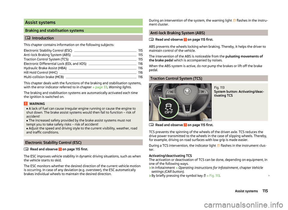
Fig. 113
System button: Activating/deac-
tivating TCS
Read and observe on page 115 first.
TCS prevents the spinning of the wheels of the driven axle. TCS reduces the drive power transmitted to the wheels in the case of slipping wheels. Thereby,
for example, driving on road surfaces with low grip is made easier.
During a TCS intervention, the indicator light flashes in the instrument clus-
ter.
Activating/deactivating TCS
The activation or deactivation of TCS can be done, depending on equipment, in
one of the following ways.
› In Infotainment
» Operating instructions for Infotainment , chapter Vehicle
settings (CAR button) .
› By briefly pressing the symbol key
» Fig. 113 .
115Assist systems
Page 127 of 216
WARNINGIn the following situations, Front Assistant should be switched off for safe-
ty reasons.■
When the vehicle is being towed away.
■
When the vehicle is on a rolling test bench.
■
If an unfounded warning or a system action was taken.
■
When on a truck, or a car ferry service or similar.
Information messages
Read and observe
and on page 122 first.
The warning symbols are shown in the instrument cluster display. Front Assist: No sensor view.
The sensor is soiled or covered.
Stop the car, switch off the engine and clean the sensor or eliminate the dis-
turbance causing the lack of visibility » Fig. 123 on page 122 .
If the message appears again after starting the engine, the system should be disabled » page 123 . Seek help from a specialist garage.
Front Assist not available.
The system is not available for an unknown reason.
Stop the vehicle, switch off the engine and then start it again.
If the message appears again after starting the engine, the system should be disabled » page 123 . Seek help from a specialist garage.
START-STOP
Introduction
This chapter contains information on the following subjects:
Operating conditions for the system
124
Operation in vehicles with manual gearbox
125
Operation in vehicles with automatic gearbox
125
System conditioned automatic start-up
126
Manually deactivating/activating
126
Information messages
126The START-STOP system (hereinafter referred to just as the system) reduces
fuel consumption and polluting emissions and CO 2 emissions by turning the
engine off, e.g. when stopping at traffic lights, and starting the engine again
when moving off.WARNING■ Never let the vehicle roll with the engine switched off.■The brake servo unit and power steering only operate if the engine is run-
ning.
Operating conditions for the system
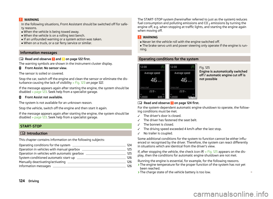
Fig. 125
Engine is automatically switched
off / automatic engine cut off is
not possible
Read and observe on page 124 first.
For the system-dependent automatic engine shutdown to operate, the follow-
ing conditions must be met.
The driver's door is closed.
The driver has fastened the seat belt.
The bonnet is closed.
The driving speed exceeded 4 km/h after the last stop.
No trailer is coupled.
Some additional conditions for the system to function cannot be either influ-
enced or recognised by the driver. Therefore, the system can react differently
in situations which are identical from the driver's view.
If, after stopping the vehicle, the check icon
» Fig. 125 appears on the dis-
play, then the conditions for automatic engine shutdown are not met.
Running the engine is essential, for example, for the following reasons.
› The engine temperature for the proper function of the system has not yet
been reached.
› The charge state of the vehicle battery is too low.
124Driving
Page 146 of 216
CAUTIONDo not use polish on plastic parts.
Rubber sealsRead and observe
and on page 142 first.
All door seals and window guides are factory-treated with a colourless matt
varnish layer against a freezing to painted body parts and against road noise.
CAUTION
■ Do not treat the door seals or window guides with any cleaning agent.■An additional treatment of the seals can attack their protective coating and
road noise may be generated.
Chrome parts
Read and observe
and on page 142 first.
First clean the chrome parts with a damp cloth and then polish them with a
soft, dry cloth.
If this method does not completely clean chrome parts, use a specific chrome
care product.
CAUTION
Do not polish the chrome parts in a dusty environment - there is a risk of
scratching the finish.
Decorative films
Read and observe
and on page 142 first.
Wash the films with a mild soap solution and clean, warm water.
The following instructions must be observed for the high-pressure washing
the vehicle.
› The minimum distance between the nozzle and the vehicle body should be
50 cm.
› Keep the jet perpendicular to the film surface.
› The maximum water temperature is 50 °C.
› The maximum water pressure is 80 bar.
CAUTION■
Never use aggressive cleaning agents or chemical solvents for the glued sur-
faces with films - there is a danger of film damage.■
No ice scrapers should be used in the winter months to remove ice and snow
from the areas to which films have been applied. Do not remove frozen snow
or ice using other objects - there is a risk of damage to the film.
Windows and external mirrors
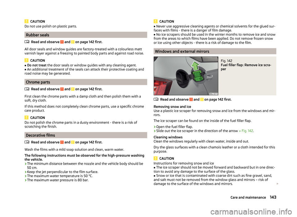
Fig. 142
Fuel filler flap: Remove ice scra-
per
Read and observe and on page 142 first.
Removing snow and ice
Use a plastic ice scraper for removing snow and ice from the windows and mir-
rors.
The ice scraper can be found on the inside of the fuel filler flap.
›
Open the fuel filler flap.
›
Slide out the ice scraper in the direction of the arrow » Fig. 142.
Cleaning windows
Clean the windows regularly with clean water, inside and out.
Dry the glass surfaces with a clean chamois leather or a cloth intended for this
purpose.
CAUTION
Instructions for removing snow and ice■The ice scraper should not be moved forward and backward but in one direc-
tion to avoid any damage to the surface of the glass.■
Snow or ice that is contaminated with coarse dirt such as fine gravel, sand,
and salt must not be removed from the window glass and mirrors – risk of
damage to the surface of the windows and mirrors.
143Care and maintenance
Page 151 of 216
Inspecting and replenishing
Fuel
Introduction
This chapter contains information on the following subjects:
Refuelling
148
Lead-free petrol
149
Diesel fuel
150
The correct fuel grades for your vehicle are specified on the inside of the fuel
filler flap » Fig. 143 on page 148 .
CAUTION
■
Never drive until the fuel tank is completely empty! The irregular supply of
fuel can cause misfiring, which can result in damage to parts of the engine and
the exhaust system.■
Immediately remove any fuel that has spilled onto the vehicle's paintwork –
there is a risk of paint damage.
■
If the vehicle was not purchased in the country in which it was intended to
be operated, you should check whether the fuel specified by the manufacturer
is offered in the country where the vehicle will be operated. You should also
perhaps check whether the manufacturer has recommended a different fuel
for operation of the vehicle in the country concerned. If no prescribed fuel is
available, then you must check whether it is permitted by the manufacturer to
operate the vehicle with another fuel type.
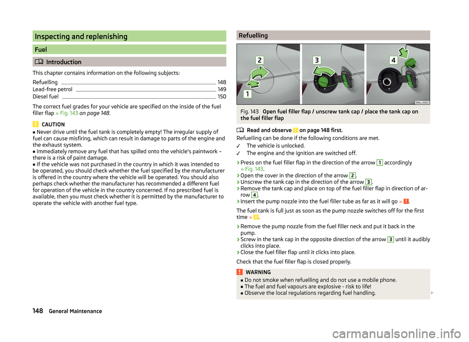
RefuellingFig. 143
Open fuel filler flap / unscrew tank cap / place the tank cap on
the fuel filler flap
Read and observe
on page 148 first.
Refuelling can be done if the following conditions are met. The vehicle is unlocked.
The engine and the ignition are switched off.
›
Press on the fuel filler flap in the direction of the arrow
1
accordingly
» Fig. 143 .
›
Open the cover in the direction of the arrow
2
.
›
Unscrew the tank cap in the direction of the arrow
3
.
›
Remove the tank cap and place on top of the fuel filler flap in direction of ar-
row
4
.
›
Insert the pump nozzle into the fuel filler tube as far as it will go » .
The fuel tank is full just as soon as the pump nozzle switches off for the first
time »
.
›
Remove the pump nozzle from the fuel filler neck and put it back in the
pump.
›
Screw in the tank cap in the opposite direction of the arrow
3
until it audibly
clicks into place.
›
Close the fuel filler flap until it clicks into place.
Check that the fuel filler flap is closed properly.
WARNING■ Do not smoke when refuelling and do not use a mobile phone.■The fuel and fuel vapours are explosive - risk to life!■
Observe the local regulations regarding fuel handling.
148General Maintenance