battery SKODA FABIA 2014 3.G / NJ Owner's Guide
[x] Cancel search | Manufacturer: SKODA, Model Year: 2014, Model line: FABIA, Model: SKODA FABIA 2014 3.G / NJPages: 216, PDF Size: 30.7 MB
Page 162 of 216
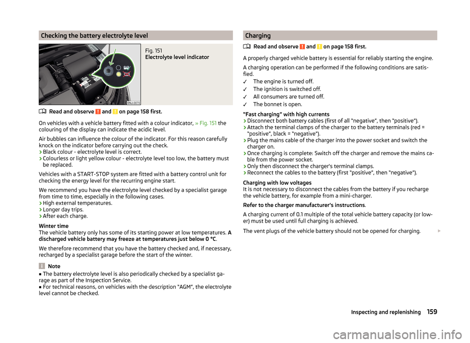
Checking the battery electrolyte levelFig. 151
Electrolyte level indicator
Read and observe and on page 158 first.
On vehicles with a vehicle battery fitted with a colour indicator, » Fig. 151 the
colouring of the display can indicate the acidic level.
Air bubbles can influence the colour of the indicator. For this reason carefully knock on the indicator before carrying out the check.
› Black colour - electrolyte level is correct.
› Colourless or light yellow colour - electrolyte level too low, the battery must
be replaced.
Vehicles with a START-STOP system are fitted with a battery control unit for
checking the energy level for the recurring engine start.
We recommend you have the electrolyte level checked by a specialist garage from time to time, especially in the following cases.
› High external temperatures.
› Longer day trips.
› After each charge.
Winter time
The vehicle battery only has some of its starting power at low temperatures. A
discharged vehicle battery may freeze at temperatures just below 0 °C .
We therefore recommend that you have the battery checked and, if necessary,
recharged by a specialist garage before the start of the winter.
Note
■ The battery electrolyte level is also periodically checked by a specialist ga-
rage as part of the Inspection Service.■
For technical reasons, on vehicles with the description “AGM”, the electrolyte
level cannot be checked.
Charging
Read and observe
and on page 158 first.
A properly charged vehicle battery is essential for reliably starting the engine.
A charging operation can be performed if the following conditions are satis-
fied.
The engine is turned off.
The ignition is switched off.
All consumers are turned off.
The bonnet is open.
“Fast charging” with high currents
›
Disconnect both battery cables (first of all “negative”, then “positive”).
›
Attach the terminal clamps of the charger to the battery terminals (red =
“positive”, black = “negative”).
›
Plug the mains cable of the charger into the power socket and switch the
charger on.
›
Once charging is complete: Switch off the charger and remove the mains ca-
ble from the power socket.
›
Only then disconnect the charger's terminal clamps.
›
Reconnect the cables to the battery (first “positive”, then “negative”).
Charging with low voltages
It is not necessary to disconnect the cables from the battery if you recharge
the vehicle battery, for example from a mini-charger.
Refer to the charger manufacturer's instructions .
A charging current of 0.1 multiple of the total vehicle battery capacity (or low-
er) must be used until full charging is achieved.
The vent plugs of the vehicle battery should not be opened for charging.
159Inspecting and replenishing
Page 163 of 216
WARNING■When you charge a battery, hydrogen is released, and a highly explosive
gas mixture is also produced. An explosion can be caused through sparkling
over during unclamping or loosening of the cable plug while the ignition is
on.■
Creating a bridge between the poles on the battery (e.g. with metal ob-
jects - cables) creates a short circuit - risk of damage to the battery, explo-
sion and burning of the battery, jets of acid spurting out.
■
Avoid creating sparks when working with cables and electrical devices.
Strong sparking represents a risk of injury.
■
Before carrying out any work on the electrical system, switch off the en-
gine, the ignition and all electrical consumers and disconnect the negative
terminal
.
■
“Quick-charging” the vehicle battery is dangerous and requires a special
charger and specialist knowledge.
■
We therefore recommend that vehicle batteries be “rapidly charged” by a
specialist garage.
CAUTION
On vehicles with the START/STOP system or additional heating (auxiliary heat-
ing), the pole terminal of the charger must not be connected directly to the
negative terminal of the vehicle battery, but only to the engine earth
» page 176 .
Replacing
Read and observe
and on page 158 first.
The new vehicle battery must have the same capacity, voltage, current and the
same size as the original battery. Suitable vehicle battery types can be pur-
chased from a specialist garage.
We recommend that the battery is replaced by a specialist garage, where the
new vehicle battery will be installed properly and the original battery will be
disposed of in accordance with national regulations.
Disconnecting or reconnecting
Read and observe
and on page 158 first.
Disconnecting
›
Switch off the ignition.
›First, disconnect the negative terminal
first, then the positive terminal
of the battery.
Connecting›
First, connect the positive
first, then the negative
battery terminal.
After disconnecting and re-connecting the vehicle battery, the following func-
tions or devices are partially or completely inoperative.
Function / deviceOperating measureElectric window levers» page 58RadioEnter code » operating instruc-
tions for the Infotainment dis-
play radioTime settings» page 33
CAUTION
■ Disconnect the vehicle battery only with the ignition turned off - there is a
risk of damaging the electrical system of the vehicle.■
Under no circumstances must the battery cables be connected incorrectly –
risk of a cable fire.
Note
■ After disconnecting and re-connecting the vehicle battery, we recommend
having the vehicle checked by a specialist to ensure that the full functionality
of all electrical systems is guaranteed.■
The data of the multi-function display will be reset.
Automatic load deactivation
Read and observe
and on page 158 first.
The vehicle voltage control unit automatically prevents the battery from dis-
charging when the battery is subjected to heavy loads. This may be noticed
from the following.
› The idling speed is raised to allow the generator to deliver more electricity to
the electrical system.
› Where appropriate large convenience consumers, e.g. seat heaters, rear win-
dow heaters, have their power limited or shut off completely if necessary.
160General Maintenance
Page 164 of 216
CAUTION■Despite such intervention by the vehicle electric system management, the
vehicle battery may be drained. For example, when the ignition is switched on
a long time with the engine turned off or the side or parking lights are turned
on during longer parking.■
Consumers which are supplied via a 12 V socket can cause the vehicle battery
to discharge when the ignition is switched off.
Note
Driving comfort is not disrupted by any shutting off of consumers. Often the
driver is not aware of it having taken place.Wheels
Tyres and rims
Introduction
This chapter contains information on the following subjects:
Notes on using wheels
161
Tyre pressure
162
Tyre wear
162
Tyre wear indicator and wheels exchange
163
Tyre damage
163
Unidirectional tyres
164
Only use those tyres or wheel rims which have been approved by ŠKODA for
your model of vehicle.
WARNINGNational legal requirements must be observed for the use of tyres.WARNINGFor safety reasons, do no replace tyres individually.
For the sake of the environment
Old and unserviceable tyres are a polluting hazardous waste. These must be disposed of in accordance with national legislation.
Note
■ We recommend that any work on the wheels or tyres is carried out by a spe-
cialist garage.■
We recommend that you use wheel rims, tyres, full wheel trims and snow
chains from ŠKODA Original Accessories.
Notes on using wheels
Read and observe
on page 161 first.
During the first 500 km, new tyres do not offer optimum grip and appropriate
care should therefore be taken when driving.
Always fit the tyres with the deeper tread depth to the front wheels.
161Wheels
Page 179 of 216

›Continue driving carefully to the nearest specialist garage at a maximum
speed of 80 km/h (50 mph).WARNING■ A tyre filled with sealant has the same driving characteristics as a stand-
ard tyre.■
Do not drive faster than 80 km/h (50 mph).
■
Avoid accelerating at full throttle, sharp braking and fast cornering.
Jump-starting
Introduction
This chapter contains information on the following subjects:
Jump-starting using the battery from another vehicle
176
The battery of another vehicle can be used to jump-start your vehicle if the en-
gine will not start because the battery is flat.
WARNING■ Pay attention to the warning instructions relating to working in the en-
gine compartment » page 150.■
A discharged vehicle battery can freeze at temperatures just below 0 °C.
If the battery is frozen, do not jump start with the battery of another vehi-
cle – risk of explosion.
■
Keep any sources of ignition (naked flame, smouldering cigarettes, etc.)
away from the battery – risk of explosion!
■
Never jump-start vehicle batteries with an electrolyte level that is too low
– risk of explosion and caustic burns.
■
The vent screws of the battery cells must be tightened firmly.
Note
We recommend you buy jump-start cables from a car battery specialist.Jump-starting using the battery from another vehicleFig. 166
Jump-starting: A – flat battery, B
– battery providing current
Fig. 167
Engine earth: START-STOP sys-
tem
Read and observe on page 176 first.
The starting process using the battery of another vehicle requires the use of
jumper cables.
The jump-start cables must be attached in the following sequence.
›
Attach clamp
1
to the positive terminal of the discharged battery
A
» Fig. 166 .
›
Attach clamp
2
to the positive terminal of the battery supplying power
B
.
›
Attach clamp
3
to the negative terminal of the battery supplying power
B
.
›
Attach the clamp
4
to a solid metal component firmly connected to the en-
gine block or to the engine block itself.
The jump-start cable must only be connected to the engine earthing point on
vehicles with the START-STOP system » Fig. 167.
Starting engine
›
Start the engine on the vehicle providing the power and allow it to idle.
›
Start the engine of the vehicle with the discharged battery.
176Do-it-yourself
Page 180 of 216

›If the engine does not start, halt the attempt to start the engine after 10 sec-
onds and wait for 30 seconds before repeating the process.›
Detach the jumper cables in the exact reverse order that they were attached.
Both batteries must have a rated voltage of 12 V. The capacity (Ah) of the bat-
tery supplying the power must not be significantly less than the capacity of
the discharged battery in your vehicle.
Jump-start cables
Only use jump-start cables which have an adequately large cross-section and
insulated terminal clamps. Obey the instructions of the jump start cable manu-
facturer.
Positive cable - colour coding in the majority of cases is red.
Negative cable - colour coding in the majority of cases is black.
WARNING■
Do not clamp the jump-start cable to the negative terminal of the dis-
charged battery. There is the risk of detonating gas seeping out the battery
being ignited by the strong spark which results from the engine being star-
ted.■
The non-insulated parts of the terminal clamps must never touch each
other – risk of short circuit.
■
The jump-start cable connected to the positive terminal of the battery
must not come into contact with electrically conducting parts of the vehicle
– risk of short circuit.
■
Route the jump-start cables so that they cannot be caught by any rotat-
ing parts in the engine compartment.
■
There must not be any contact between the two vehicles otherwise cur-
rent may flow as soon as the negative terminals are connected.
Towing the vehicle
Introduction
Fig. 168
Braided tow ropes/spiral tow rope
This chapter contains information on the following subjects:
Front towing eye
178
Rear towing eye
179
Vehicles with a tow hitch
179
A braided tow rope must be used for towing » Fig. 168 -
.
The following guidelines must be observed when towing.
Vehicles with manual transmission may be towed with a tow bar or a tow rope
or with the front or rear wheels raised.
Vehicles with automatic transmission may be towed with a tow bar or a tow
rope or with the front wheels raised. If the vehicle is raised at rear, the auto-
matic gearbox is damaged!
Driver of the tow vehicle
›
Engage the clutch gently when starting off or depress the accelerator partic-
ularly gently if the vehicle is fitted with an automatic gearbox.
›
Only then, approach correctly when the rope is taut.
The maximum towing speed is 50 km/h.
Driver of the towed vehicle
›
Switch on the ignition so that the steering wheel is not locked and so that
the turn signal lights, windscreen wipers and windscreen washer system can
be used.
177Emergency equipment, and self-help
Page 181 of 216

›Take the vehicle out of gear or move the selector lever into position
N if the
vehicle is fitted with an automatic gearbox.
Please note that the brake servo unit and power steering only operate if the
engine is running. If the engine is not running, significantly more physical force
is required to depress the brake pedal and steer the vehicle.
If using a tow rope, ensure that it is always kept taught.
Both drivers should be familiar with the potential issues of towing a vehicle.
Unskilled drivers should not attempt to tow another vehicle or to be towed.
The vehicle must be transported on a special breakdown vehicle or trailer if it
is not possible to tow the vehicle in the way described or if the towing dis-
tance is greater than 50 km.WARNING■ When towing, respect the national legal provisions, especially those
which relate to the identification of the towing vehicle and the vehicle be-
ing towed.■
Exercise increased caution when towing.
■
Spiral tow ropes must not be used for towing » Fig. 168 -
, the towing
eye may unscrew out of the vehicle - risk of accident.
■
The tow rope should not be twisted - risk of accident.
CAUTION
■ Do not tow-start the engine – risk of damaging the engine and the catalytic
converter. The battery from another vehicle can be used as a jump-start aid
» page 176 , Jump-starting .■
If the gearbox no longer contains any oil because of a defect, your vehicle
must only be towed with the drive wheels raised clear of the ground or on a
special breakdown vehicle or trailer.
■
To protect both vehicles when tow-starting or towing, the tow rope should
be elastic. Thus one should only use plastic fibre rope or a rope made out of a
similarly elastic material.
■
There is always a risk of excessive stresses and damage resulting at the
points to which you attach the tow rope or tow bar when you attempt to tow a
vehicle which is not standing on a paved road.
■
Attach the tow rope or the tow bar to the towing eyes » page 178 or
» page 179 to the detachable ball head of the towing equipment » page 129 .
NoteWe recommend using a tow rope from ŠKODA Original Accessories available
from a ŠKODA Partner.
Front towing eye
Fig. 169
Removing the cap / installing the towing eye
Read and observe
and on page 178 first.
Removing/installing the cap
›
Press on the fuel filler flap in the direction of the arrow
1
» Fig. 169 .
›
Remove the cap in the direction of the arrow
2
.
›
After unscrewing the cap of the towing eye, insert the cap in the region of
the arrow
1
and then press the opposite side of the cap.
The cap must engage firmly.
Removing/installing the towing eye
›
Manually screw the towing eye as far as it will go in the direction of the ar-
row
3
» Fig. 169 » .
For tightening purposes, we recommend, for example, using the wheel
wrench, towing eye from another vehicle or a similar object that can be pushed through the eye.
›
Unscrew the towing eye against the direction of the arrow
3
.
WARNINGThe towing eye must always be screwed in fully and firmly tightened, oth-
erwise the towing eye can tear when towing in or tow-starting.178Do-it-yourself
Page 182 of 216

Rear towing eyeFig. 170
Rear towing eye
Read and observe and on page 178 first.
The rear towing eye is located below the rear bumper on the right » Fig. 170.
Vehicles with a tow hitch
Read and observe
and on page 178 first.
The removable towing ball may be fitted and used for towing on vehicles witha factory fitted tow hitch » page 129, Hitch .
Towing the vehicle using the towing device is a viable alternative solution to
using the towing eye.
CAUTION
The detachable ball rod and/or the vehicle can be damaged if an unsuitable
tow bar is used.
Remote control
Introduction
This chapter contains information on the following subjects:
Replacing the battery in the remote control key
179
Synchronising the remote control
180CAUTION■ The replacement battery must have the same specification as the original
battery.■
We recommend having faulty rechargeable batteries replaced by a ŠKODA
service partner.
■
Pay attention to the correct polarity when changing the battery.
For the sake of the environment
Dispose of the used battery in accordance with national legal provisions.
Replacing the battery in the remote control key
Fig. 171
Remove cover/take out battery
Read and observe
on page 179 first.
The battery change is carried out as follows.
›
Flip out the key.
›
Press off the battery cover
A
» Fig. 171 with your thumb or by using a flat
screwdriver in region
B
.
›
Open the battery in the direction of the arrow
1
.
›
Remove the discharged battery in the direction of arrow
2.›
Insert the new battery.
›
Insert the battery cover
A
and press it down until it clicks audibly into place.
The key has to be synchronised if the vehicle cannot be unlocked or locked
with the remote control key after replacing the battery » page 180.
Note
Replacing the battery in the key a glued decorative cover requires the cover to
be destroyed. A replacement cover can be purchased from a ŠKODA Partner.179Emergency equipment, and self-help
Page 183 of 216

Synchronising the remote controlRead and observe
on page 179 first.
If the vehicle does not unlock when the remote control is pressed, the key maynot be synchronised. This can occur when the buttons on the remote control
key are actuated a number of times outside of the operative range of the
equipment or the battery in the remote control key has been replaced.
Synchronise the key as follows.
›
Press any button on the remote control key.
›
Unlock the door with the key in the lock cylinder within 1 minute of pressing the button.
Emergency unlocking/locking
Introduction
This chapter contains information on the following subjects:
Unlocking/locking the driver's door
180
Locking the door without a locking cylinder
180
Unlocking the tailgate
181
Selector lever-emergency unlocking
181
Unlocking/locking the driver's door
Fig. 172
Handle on the driver's door: covered locking cylinder / locking
cylinder with key
The driver's door can be unlocked or locked in an emergency.
›
Pull on the door handle and hold it pulled.
› Insert the vehicle key into the slot on the bottom of the cover
» Fig. 172.›Open the cover in the direction of the arrow.›
Release the door handle.
›
For vehicles with LHD insert the remote control key with the buttons facing
up into the lock cylinder and unlock or lock the vehicle.
›
For vehicles with RHD insert the remote control key directed with buttons
down into the lock cylinder and unlock or lock the vehicle.
›
Pull on the door handle and hold it pulled.
›
Replace the cap in its original position.
CAUTION
Make sure you do not damage the paint when performing an emergency lock-
ing/unlocking.
Locking the door without a locking cylinder
Fig. 173
Emergency locking: Left/right rear door
An emergency locking mechanism is located on the face side of the doors
which have no locking cylinder. It is only visible after opening the door.
›
Remove the cover
A
» Fig. 173 .
›
Insert the vehicle key into the slot and turn in the direction of the arrow
(sprung position).
›
Replace the cover
A
.
180Do-it-yourself
Page 204 of 216
Index
Numbers and Symbols
12-volt power outlet
79
A
abroad lead-free petrol
149
Abroad Headlights
65
ABS Function
115
warning light36
Acceptance and recycling of used vehicles140
Accessories137
Adjusting Belt height
15
Exterior mirrors70
headrests72
Interior mirror70
Seat72
Steering wheel10
Adjusting the seats9
Adjustment Headlight beam
60
Adjustments and technical changes Spoiler
139
Adjustments and technical modifications Airbags
139
Advance warning/emergency braking Warning symbol
42
Air-conditioning system Air outlet vents
96
Airbag16
Adjustments and impairment of the airbag sys- tem
139
Deactivating20
Deployment16
Front airbag17
Head airbag19
Indicator light36
Side airbag18
Switching off the front passenger airbag21
Airbag system16
Air conditioning95
Climatronic98
manual air conditioning98
Recirculated air mode96
Air outlet vents96
Alarm Switching off
54
Triggering54
Alcantara cleaning
146
Anti-lock Braking System115
Anti-theft alarm system Activating/deactivating
55
Trailer136
Anti-theft wheel bolts 173
Armrest74
artificial leather146
Ashtray79
ASR Indicator light
35
Assembling the bar ball, Step 1
131
bar ball, Step 2131
Assistance systems ASR
35
ESC35
Front Assistant121
MCB116
Parking aid117
Speed Limiter120
Assist system ABS
115
Assist systems115
ABS36
Cruise control system118
EDL116
ESC115
HBA116
HHC116
START-STOP124
TCS115
XDS116
Audio see Infotainment
4
Auto-check control44
Automatic driving lamp control62
Automatic gearbox Selector lever-emergency unlocking
181
Selector lever lock111
Starting-off and driving112
Tiptronic112
Using the selector lever111
Automatic gearbox modes111
Automatic load deactivation160
automatic transmission selector lever lock defect
111
Automatic transmission110
Kickdown112
malfunctions39
Selector lever lock111
Warning icon39
Warning messages39
B
Ball head Check fitting
132
Ready position130
Battery In the remote control key
179
Belts12
Belt tensioners15
Bicycle carrier91
Bonnet Closing
152
Opening152
201Index
Page 205 of 216
BootClass N1 vehicles89
Hooks86
See Boot lid56
Boot lid automatic locking
56
Closing56
Opening56
Brake booster108
brake fluid specification
157
Brake fluid156
Checking157
Information messages34
Brake pedal (automatic transmission) Indicator light
38
brakes Driving in
113
Brakes Brake booster
108
Brake fluid157
Braking and stabilisation systems115
Handbrake108
Information messages34
Warning light34
Brakes and parking107
Braking Information for braking
107
Breakdown kit173
Break recommendation See Fatigue detection
126
Bulbs Replacing
186
Button CAR see Infotainment
4
C
Car care Jack
144
Car computersee multifunction display45
Care and maintenance137
Car park109
Car park ticket holder76
Carrier Roof rack
93
Cavity protection144
Central locking49
Problems54
Central locking button53
Central warning light Indicator light
34
Change Bulb for daytime running lights (halogen spot-light)
189
Bulb for indicator (halogen headlight)188
Engine oil153
Light bulb in tail light192
Changing Fuses
182
Fuses in the dash panel183
Fuses in the engine compartment185
Licence plate light bulb191
Wheels170
Changing a wheel Preparation
170
Removing and fitting a wheel171
Subsequent steps171
Charging a vehicle battery159
Check Fit ball head properly
132
Checking Battery electrolyte level
159
Brake fluid157
Coolant level156
Engine oil154
Oil level154
Windscreen washer fluid153
Checks Statutory checks137
Children and safety22
Child safety Side airbag
24
Child safety lock54
Child safety seat Use of child safety seats
24
child seat Use of ISOFIX child seats
25
Child seat Classification
24
ISOFIX25
on the front passenger seat23
TOP TETHER26
Chrome parts see vehicle care
143
Cigarette lighter78
cleaning chrome parts
143
Cleaning Alcantara
146
and maintaining belts147
artificial leather146
headlight glasses144
materials146
natural leather146
plastic parts142
seats covers of the electrically heated seats147
wheels144
Cleaning safety belt
147
Cleaning seat covers
147
Cleaning the interior artificial leather
146
Seat covers147
Cleaning the outside of the vehicle Decorative films
143
202Index