ECU SKODA KODIAQ 2016 1.G User Guide
[x] Cancel search | Manufacturer: SKODA, Model Year: 2016, Model line: KODIAQ, Model: SKODA KODIAQ 2016 1.GPages: 344, PDF Size: 58.96 MB
Page 87 of 344
Seat heating and ventilation
Introduction
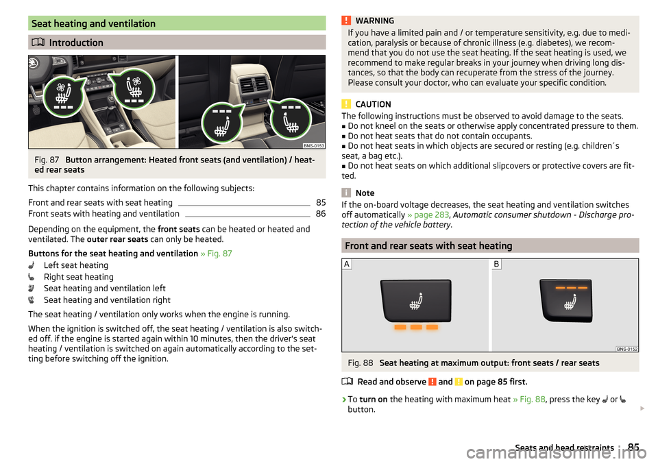
Fig. 87
Button arrangement: Heated front seats (and ventilation) / heat-
ed rear seats
This chapter contains information on the following subjects:
Front and rear seats with seat heating
85
Front seats with heating and ventilation
86
Depending on the equipment, the front seats can be heated or heated and
ventilated. The outer rear seats can only be heated.
Buttons for the seat heating and ventilation » Fig. 87
Left seat heating
Right seat heating
Seat heating and ventilation left
Seat heating and ventilation right
The seat heating / ventilation only works when the engine is running. When the ignition is switched off, the seat heating / ventilation is also switch-ed off. if the engine is started again within 10 minutes, then the driver's seat
heating / ventilation is switched on again automatically according to the set-
ting before switching off the ignition.
WARNINGIf you have a limited pain and / or temperature sensitivity, e.g. due to medi-
cation, paralysis or because of chronic illness (e.g. diabetes), we recom-
mend that you do not use the seat heating. If the seat heating is used, we
recommend to make regular breaks in your journey when driving long dis-
tances, so that the body can recuperate from the stress of the journey.
Please consult your doctor, who can evaluate your specific condition.
CAUTION
The following instructions must be observed to avoid damage to the seats.■Do not kneel on the seats or otherwise apply concentrated pressure to them.■
Do not heat seats that do not contain occupants.
■
Do not heat seats in which objects are secured or resting (e.g. children´s
seat, a bag etc.).
■
Do not heat seats on which additional slipcovers or protective covers are fit-
ted.
Note
If the on-board voltage decreases, the seat heating and ventilation switches
off automatically » page 283, Automatic consumer shutdown - Discharge pro-
tection of the vehicle battery .
Front and rear seats with seat heating
Fig. 88
Seat heating at maximum output: front seats / rear seats
Read and observe
and on page 85 first.
›
To turn on the heating with maximum heat » Fig. 88, press the key
or
button.
85Seats and head restraints
Page 97 of 344
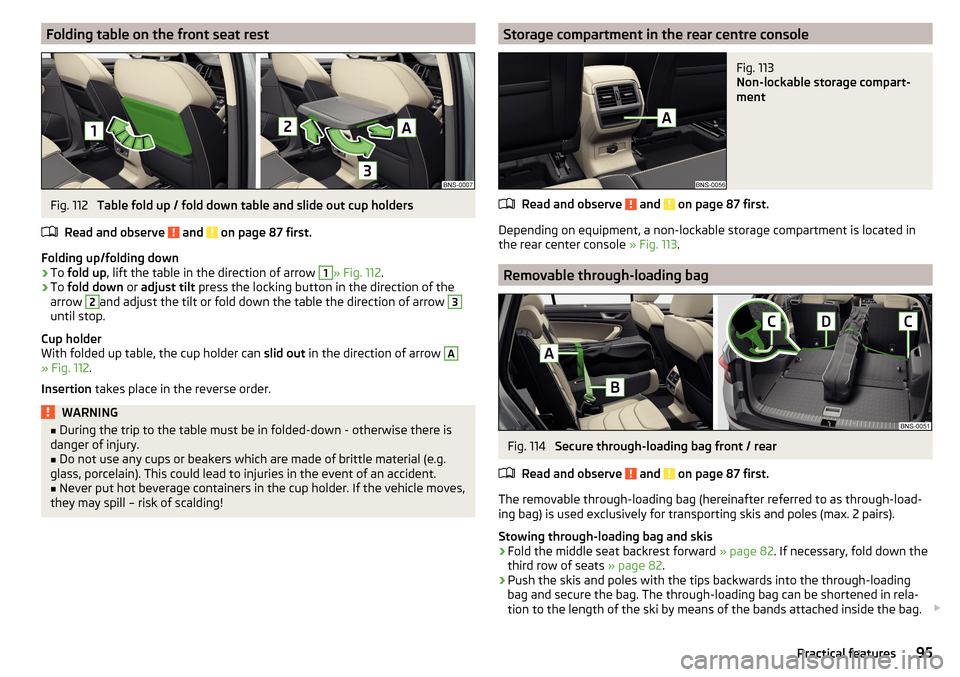
Folding table on the front seat restFig. 112
Table fold up / fold down table and slide out cup holders
Read and observe
and on page 87 first.
Folding up/folding down
›
To fold up , lift the table in the direction of arrow
1
» Fig. 112 .
›
To fold down or adjust tilt press the locking button in the direction of the
arrow
2
and adjust the tilt or fold down the table the direction of arrow
3
until stop.
Cup holder
With folded up table, the cup holder can slid out in the direction of arrow
A
» Fig. 112 .
Insertion takes place in the reverse order.
WARNING■
During the trip to the table must be in folded-down - otherwise there is
danger of injury.■
Do not use any cups or beakers which are made of brittle material (e.g.
glass, porcelain). This could lead to injuries in the event of an accident.
■
Never put hot beverage containers in the cup holder. If the vehicle moves,
they may spill – risk of scalding!
Storage compartment in the rear centre consoleFig. 113
Non-lockable storage compart-
ment
Read and observe and on page 87 first.
Depending on equipment, a non-lockable storage compartment is located in
the rear center console » Fig. 113.
Removable through-loading bag
Fig. 114
Secure through-loading bag front / rear
Read and observe
and on page 87 first.
The removable through-loading bag (hereinafter referred to as through-load-
ing bag) is used exclusively for transporting skis and poles (max. 2 pairs).
Stowing through-loading bag and skis
›
Fold the middle seat backrest forward » page 82. If necessary, fold down the
third row of seats » page 82.
›
Push the skis and poles with the tips backwards into the through-loading
bag and secure the bag. The through-loading bag can be shortened in rela-
tion to the length of the ski by means of the bands attached inside the bag.
95Practical features
Page 98 of 344
›Place the empty through-loading bag in the opening in such a way that the
end of the bag with the zip is in the luggage compartment.
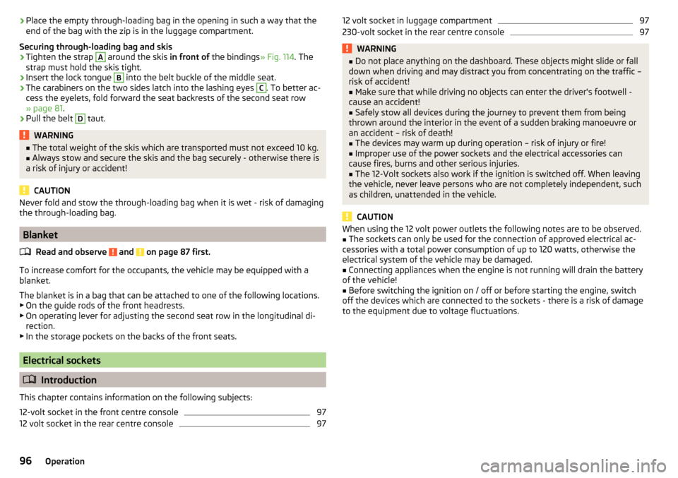
Securing through-loading bag and skis›
Tighten the strap
A
around the skis in front of the bindings » Fig. 114. The
strap must hold the skis tight.
›
Insert the lock tongue
B
into the belt buckle of the middle seat.
›
The carabiners on the two sides latch into the lashing eyes
C
. To better ac-
cess the eyelets, fold forward the seat backrests of the second seat row
» page 81 .
›
Pull the belt
D
taut.
WARNING■
The total weight of the skis which are transported must not exceed 10 kg.■Always stow and secure the skis and the bag securely - otherwise there is
a risk of injury or accident!
CAUTION
Never fold and stow the through-loading bag when it is wet - risk of damaging
the through-loading bag.
Blanket
Read and observe
and on page 87 first.
To increase comfort for the occupants, the vehicle may be equipped with a
blanket.
The blanket is in a bag that can be attached to one of the following locations.
▶ On the guide rods of the front headrests.
▶ On operating lever for adjusting the second seat row in the longitudinal di-
rection.
▶ In the storage pockets on the backs of the front seats.
Electrical sockets
Introduction
This chapter contains information on the following subjects:
12-volt socket in the front centre console
97
12 volt socket in the rear centre console
9712 volt socket in luggage compartment97230-volt socket in the rear centre console97WARNING■ Do not place anything on the dashboard. These objects might slide or fall
down when driving and may distract you from concentrating on the traffic –
risk of accident!■
Make sure that while driving no objects can enter the driver's footwell -
cause an accident!
■
Safely stow all devices during the journey to prevent them from being
thrown around the interior in the event of a sudden braking manoeuvre or
an accident – risk of death!
■
The devices may warm up during operation – risk of injury or fire!
■
Improper use of the power sockets and the electrical accessories can
cause fires, burns and other serious injuries.
■
The 12-Volt sockets also work if the ignition is switched off. When leaving
the vehicle, never leave persons who are not completely independent, such
as children, unattended in the vehicle.
CAUTION
When using the 12 volt power outlets the following notes are to be observed.■The sockets can only be used for the connection of approved electrical ac-
cessories with a total power consumption of up to 120 watts, otherwise the
electrical system of the vehicle may be damaged.■
Connecting appliances when the engine is not running will drain the battery
of the vehicle!
■
Before switching the ignition on / off or before starting the engine, switch
off the devices which are connected to the sockets - there is a risk of damage
to the equipment due to voltage fluctuations.
96Operation
Page 101 of 344
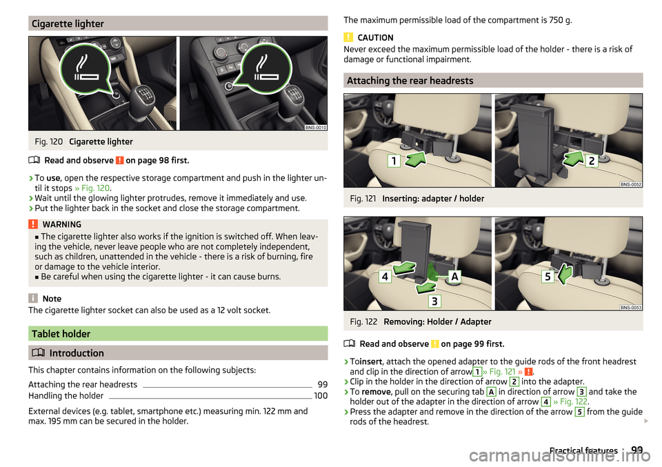
Cigarette lighterFig. 120
Cigarette lighter
Read and observe
on page 98 first.
›
To use , open the respective storage compartment and push in the lighter un-
til it stops » Fig. 120.
›
Wait until the glowing lighter protrudes, remove it immediately and use.
›
Put the lighter back in the socket and close the storage compartment.
WARNING■
The cigarette lighter also works if the ignition is switched off. When leav-
ing the vehicle, never leave people who are not completely independent,
such as children, unattended in the vehicle - there is a risk of burning, fire
or damage to the vehicle interior.■
Be careful when using the cigarette lighter - it can cause burns.
Note
The cigarette lighter socket can also be used as a 12 volt socket.
Tablet holder
Introduction
This chapter contains information on the following subjects:
Attaching the rear headrests
99
Handling the holder
100
External devices (e.g. tablet, smartphone etc.) measuring min. 122 mm and
max. 195 mm can be secured in the holder.
The maximum permissible load of the compartment is 750 g.
CAUTION
Never exceed the maximum permissible load of the holder - there is a risk of
damage or functional impairment.
Attaching the rear headrests
Fig. 121
Inserting: adapter / holder
Fig. 122
Removing: Holder / Adapter
Read and observe
on page 99 first.
›
To insert , attach the opened adapter to the guide rods of the front headrest
and clip in the direction of arrow
1
» Fig. 121 » .
›
Clip in the holder in the direction of arrow
2
into the adapter.
›
To remove , pull on the securing tab
A
in direction of arrow
3
and take the
holder out of the adapter in the direction of arrow
4
» Fig. 122 .
›
Press the adapter and remove in the direction of the arrow
5
from the guide
rods of the headrest.
99Practical features
Page 102 of 344
WARNINGBe careful with the adapter- otherwise there is a risk of finger injury.
Handling the holder
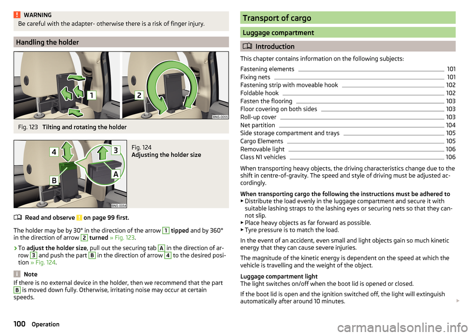
Fig. 123
Tilting and rotating the holder
Fig. 124
Adjusting the holder size
Read and observe on page 99 first.
The holder may be by 30° in the direction of the arrow
1
tipped and by 360°
in the direction of arrow
2
turned » Fig. 123 .
›
To adjust the holder size , pull out the securing tab
A
in the direction of ar-
row
3
and push the part
B
in the direction of arrow
4
to the desired posi-
tion » Fig. 124 .
Note
If there is no external device in the holder, then we recommend that the partB is moved down fully. Otherwise, irritating noise may occur at certain
speeds.Transport of cargo
Luggage compartment
Introduction
This chapter contains information on the following subjects:
Fastening elements
101
Fixing nets
101
Fastening strip with moveable hook
102
Foldable hook
102
Fasten the flooring
103
Floor covering on both sides
103
Roll-up cover
103
Net partition
104
Side storage compartment and trays
105
Cargo Elements
105
Removable light
106
Class N1 vehicles
106
When transporting heavy objects, the driving characteristics change due to the
shift in centre-of-gravity. The speed and style of driving must be adjusted ac-
cordingly.
When transporting cargo the following the instructions must be adhered to
▶ Distribute the load evenly in the luggage compartment and secure it with
suitable lashing straps to the lashing eyes or securing nets so that they can-
not slip.
▶ Place heavy objects as far forward as possible.
▶ Tyre pressure is to match the load.
In the event of an accident, even small and light objects gain so much kinetic
energy that they can cause severe injuries.
The magnitude of the kinetic energy is dependent on the speed at which the
vehicle is travelling and the weight of the object.
Luggage compartment light
The light switches on/off when the boot lid is opened or closed.
If the boot lid is open and the ignition switched off, the light will extinguish
automatically after around 10 minutes.
100Operation
Page 103 of 344
WARNING■Never exceed the maximum permissible load of the respective fasteners,
nets, hooks etc. Heavy objects were not secured sufficiently – risk of injury!■
Do not exceed the permissible axle loads and permissible gross weight of
the vehicle – risk of accident!
■
An unfixed or improperly fixed load can slip during a sudden manoeuvre
or an accident - danger of injury!
■
Loose cargo could hit a deployed airbag and injure occupants – danger of
death!
■
When transporting loads in the luggage compartment that has been en-
larged by folding the rear seats forward, ensure the safety of the passen-
gers transported on the other rear seats .
CAUTION
■ Never exceed the maximum permissible load of the respective fasteners,
nets, hooks etc. - these could be damaged.■
Make sure that the heating elements of the rear window heater, the ele-
ments of the integrated aerial in the rear window or in the rear side windows
are not damaged by abrasive items.
■
Do not place sharp objects in the nets and storage compartments in the lug-
gage compartment - there is a risk of damage to the net as well as the com-
partments.
■
Put the items in the storage compartments carefully and not load these
punctiform - there is a risk of damage to the compartments.
Fastening elements
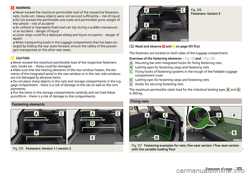
Fig. 125
Fasteners: Version 1 / version 2
Fig. 126
Fasteners: Variant 3
Read and observe and on page 101 first.
The fasteners are located on both sides of the luggage compartment.
Overview of the fastening elements » Fig. 125 and » Fig. 126
Mounting bar with integrated hooks for fixing fastening nets.
Lashing eyes for fastening cargo and fastening nets
Fixing hooks of fastening systems in the trough of the foldable luggage
compartment cover
Lashing eyes for fastening cargo and fastening nets
Hooks for securing fastening nets
The maximum permissible static load for the individual lashing eyes
B
and
D
is 350 kg.
Fixing nets
Fig. 127
Fastening examples for nets: five-seat version / five-seat version
with the variable loading floor
ABCDE101Transport of cargo
Page 104 of 344

Fig. 128
Fastening examples for nets: seven-seat vervsion
Read and observe
and on page 101 first.
Fastening examples for nets » Fig. 127 and » Fig. 128
Horizontal pocket
Floor net
Vertical pocket
Longitudinal net
Variable net
The maximum permissible load of each of the nets is 1.5 kg.
If also equipped with the variable loading floor and the spare or emergency
wheel five-seat version, the lashing eyes
D
can be used for securing the lon-
gitudinal pocket » Fig. 125 on page 101 .
Fastening strip with moveable hook
Fig. 129
Sliding hook onto the mounting bar / removing hook
ABCDERead and observe and on page 101 first.
A fastening bar is located on both sides of the luggage compartment with two
moveable hooks each, in order to attach small items of luggage, such as bags,
etc.
The maximum permissible load of each of the hooks is 7.5 kg.
Moving the hook
›
Hold hook upward in direction of arrow
1
and move to the desired position
in the direction of arrow
2
» Fig. 129 .
›
Fold down the hook until it stops in the arrow direction
3
.
Removing hooks
The hook can be removed only in the front area of the attachment bar.
›
Fold the hook upwards in direction of arrow
4
» Fig. 129 until it disengages,
and remove in the direction of arrow
5
.
Inserting hook
The hook can be removed only in the front region of the attachment bar.
›
Position the hook on the fastening strip in a vertical position in direction of
arrow
5
and lightly press on it » Fig. 129.
›
Fold down the hook until it stops against the direction of arrow
4
.
Foldable hook
Fig. 130
Fold down hook
Read and observe and on page 101 first.
One foldable hook for attaching small items of luggage, such as bags etc., is
provided on each side of the luggage compartment.
›
To use , fold down the hook in the direction of arrow » Fig. 130.
The maximum permissible load of the hook is 7.5 kg.
102Operation
Page 107 of 344
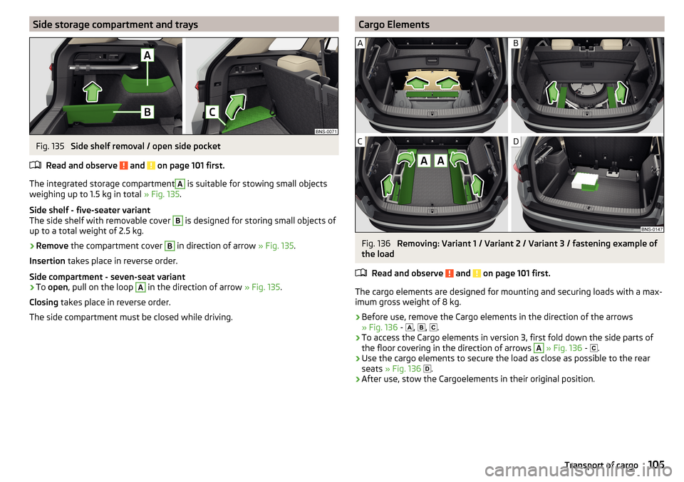
Side storage compartment and traysFig. 135
Side shelf removal / open side pocket
Read and observe
and on page 101 first.
The integrated storage compartment
A
is suitable for stowing small objects
weighing up to 1.5 kg in total » Fig. 135.
Side shelf - five-seater variant
The side shelf with removable cover
B
is designed for storing small objects of
up to a total weight of 2.5 kg.
›
Remove the compartment cover
B
in direction of arrow » Fig. 135.
Insertion takes place in reverse order.
Side compartment - seven-seat variant
›
To open , pull on the loop
A
in the direction of arrow » Fig. 135.
Closing takes place in reverse order.
The side compartment must be closed while driving.
Cargo ElementsFig. 136
Removing: Variant 1 / Variant 2 / Variant 3 / fastening example of
the load
Read and observe
and on page 101 first.
The cargo elements are designed for mounting and securing loads with a max-imum gross weight of 8 kg.
›
Before use, remove the Cargo elements in the direction of the arrows
» Fig. 136 -
,
,
.
›
To access the Cargo elements in version 3, first fold down the side parts of
the floor covering in the direction of arrows
A
» Fig. 136 -
.
›
Use the cargo elements to secure the load as close as possible to the rear
seats » Fig. 136
.
›
After use, stow the Cargoelements in their original position.
105Transport of cargo
Page 110 of 344

Dividing the luggage compartmentFig. 141
Dividing the luggage compartment
›
To subdivide the luggage compartment, lift the rear panel of the variable
loading floor by the handle
A
in direction of arrow
1
and insert into the
grooves behind the guide tabs
B
in direction of arrow
2
» Fig. 141 .
In the grooves, the variable loading floor is secured against movement.
Fold up/fold down the variable loading floor
Fig. 142
Fold front panel forward
›
To fold up the front panel, lift this using handle
A
in direction of arrow
1
.
The panel is inserted into the grooves behind the guide tabs
B
» Fig. 142 .
›
To fold down the panel, slide up the panel so that it releases from the
groove. Then fold down the panel.
Variable loading floor on both sidesFig. 143
Reversible variable loading floor
The rear panel of the variable loading floor is reversible. One side is made of
fabric, the other side is washable (suitable for transporting wet or dirty items ).
Removable partition
Fig. 144
Remove partition: five-seat variant / seven-seat variant
The luggage compartment contains a partition that prevents cargo from shift-
ing into the passenger compartment.
The partition can be removed in the direction of the arrow » Fig. 144.
Transportation on the roof rack
Roof load
The maximum permitted weight of the load incl. carriers is 75 kg.
108Operation
Page 111 of 344

WARNINGFor road safety when transporting cargo on the roof rack, observe the fol-
lowing instructions.■
Always distribute the load on the roof rack evenly and secure properly us-
ing suitable lashing straps or tensioning straps.
■
When transporting heavy objects or objects which take up a large area on
the roof rack system, the handling of the car may change as a result of the
displacement of the centre of gravity. The style of driving and speed must
therefore be adapted to the current circumstances.
■
The permissible roof load, permissible axle loads and permissible total ve-
hicle weight must not be exceeded under any circumstances – risk of acci-
dent!
CAUTION
■ Make sure that the sliding / tilting roof or the boot lid does not collide with
the roof load when opened.■
Ensure the roof aerial is not impaired by the load being transported.
Note
We recommend that you use a roof rack from ŠKODA Original Accessories.Heating and ventilation
Heating, manual air conditioning system, Climatronic
Introduction
This chapter contains information on the following subjects:
Heating and manual air conditioning
110
Climatronic (automatic air conditioning)
110
Operate Climatronic in Infotainment
112
Climatronic - automatic operation
112
Air distribution control
113
Air outlet vents
113
The heating heats and ventilates the vehicle interior. The air conditioning sys-
tem also cools and dehumidifies the vehicle interior.
The heating effect is dependent upon the coolant temperature, thus full heat
output only occurs when the engine has reached its operating temperature.
The cooling system works under the following conditions. The cooling system is switched on.
The engine is running.
The outside temperature is below 2 ° C.
The blower is switched on.
Fogging is prevented when the cooling system is switched on.
To increase the efficiency of the cooling system, recirculation mode can be
swtiched on briefly » page 113.
Health protection
To reduce health risks (e.g. common colds), the following instructions for the
use of the cooling system are to be observed. ▶ The difference between the indoor temperature and the outdoor air temper-
ature should not be greater than about 5 ° C.
▶ The cooling system should be turned off about 10 minutes before the end of
the journey.
▶ Once a year, the air conditioning should be disinfected by a specialist garage.
109Heating and ventilation