ECU SKODA KODIAQ 2016 1.G Service Manual
[x] Cancel search | Manufacturer: SKODA, Model Year: 2016, Model line: KODIAQ, Model: SKODA KODIAQ 2016 1.GPages: 344, PDF Size: 58.96 MB
Page 300 of 344
WARNING (Continued)■A discharged vehicle battery may already freeze at temperatures just be-
low 0 °C. If the battery is frozen, do not carry out a jump start with the bat-
tery of another vehicle – risk of explosion!■
Never jump-start vehicle batteries with an acid level that is too low – risk
of explosion and caustic burns!
Jump-starting using the battery from another vehicle
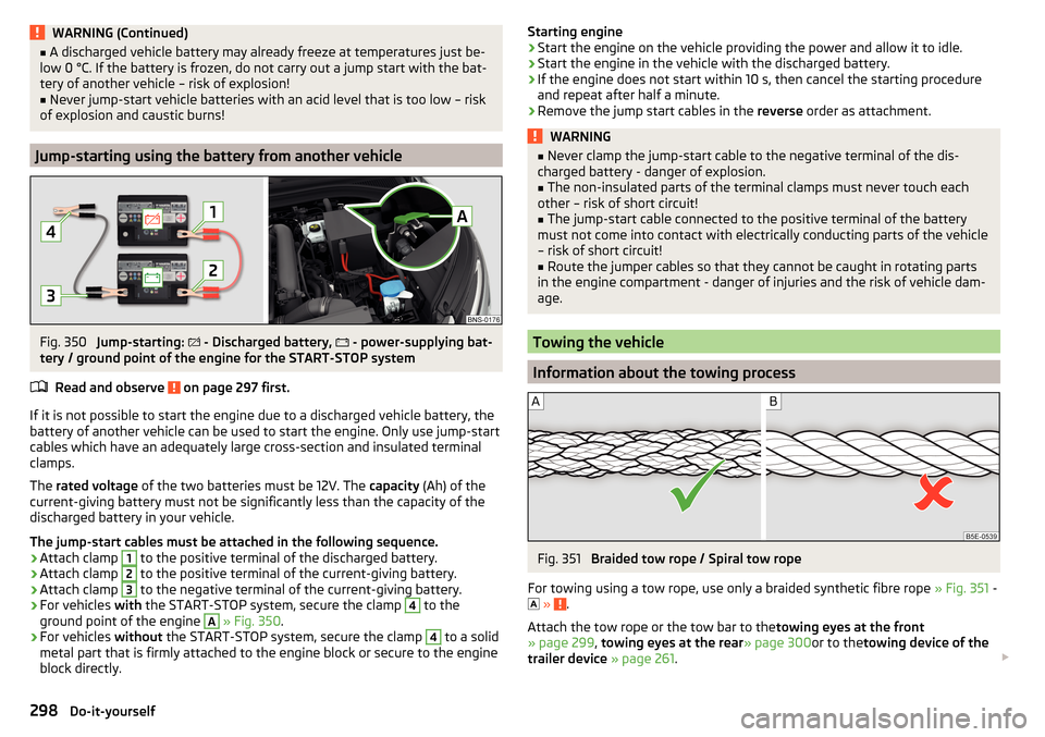
Fig. 350
Jump-starting: - Discharged battery,
- power-supplying bat-
tery / ground point of the engine for the START-STOP system
Read and observe
on page 297 first.
If it is not possible to start the engine due to a discharged vehicle battery, the
battery of another vehicle can be used to start the engine. Only use jump-start
cables which have an adequately large cross-section and insulated terminal
clamps.
The rated voltage of the two batteries must be 12V. The capacity (Ah) of the
current-giving battery must not be significantly less than the capacity of the
discharged battery in your vehicle.
The jump-start cables must be attached in the following sequence.
›
Attach clamp
1
to the positive terminal of the discharged battery.
›
Attach clamp
2
to the positive terminal of the current-giving battery.
›
Attach clamp
3
to the negative terminal of the current-giving battery.
›
For vehicles with the START-STOP system, secure the clamp
4
to the
ground point of the engine
A
» Fig. 350 .
›
For vehicles without the START-STOP system, secure the clamp
4
to a solid
metal part that is firmly attached to the engine block or secure to the engine
block directly.
Starting engine›Start the engine on the vehicle providing the power and allow it to idle.›
Start the engine in the vehicle with the discharged battery.
›
If the engine does not start within 10 s, then cancel the starting procedure
and repeat after half a minute.
›
Remove the jump start cables in the reverse order as attachment.
WARNING■
Never clamp the jump-start cable to the negative terminal of the dis-
charged battery - danger of explosion.■
The non-insulated parts of the terminal clamps must never touch each
other – risk of short circuit!
■
The jump-start cable connected to the positive terminal of the battery
must not come into contact with electrically conducting parts of the vehicle
– risk of short circuit!
■
Route the jumper cables so that they cannot be caught in rotating parts
in the engine compartment - danger of injuries and the risk of vehicle dam-
age.
Towing the vehicle
Information about the towing process
Fig. 351
Braided tow rope / Spiral tow rope
For towing using a tow rope, use only a braided synthetic fibre rope » Fig. 351 -
»
.
Attach the tow rope or the tow bar to the towing eyes at the front
» page 299 , towing eyes at the rear » page 300or to thetowing device of the
trailer device » page 261 .
298Do-it-yourself
Page 313 of 344
Replace bulb for fog lights (halogen headlight)Fig. 378
Remove plastic cover
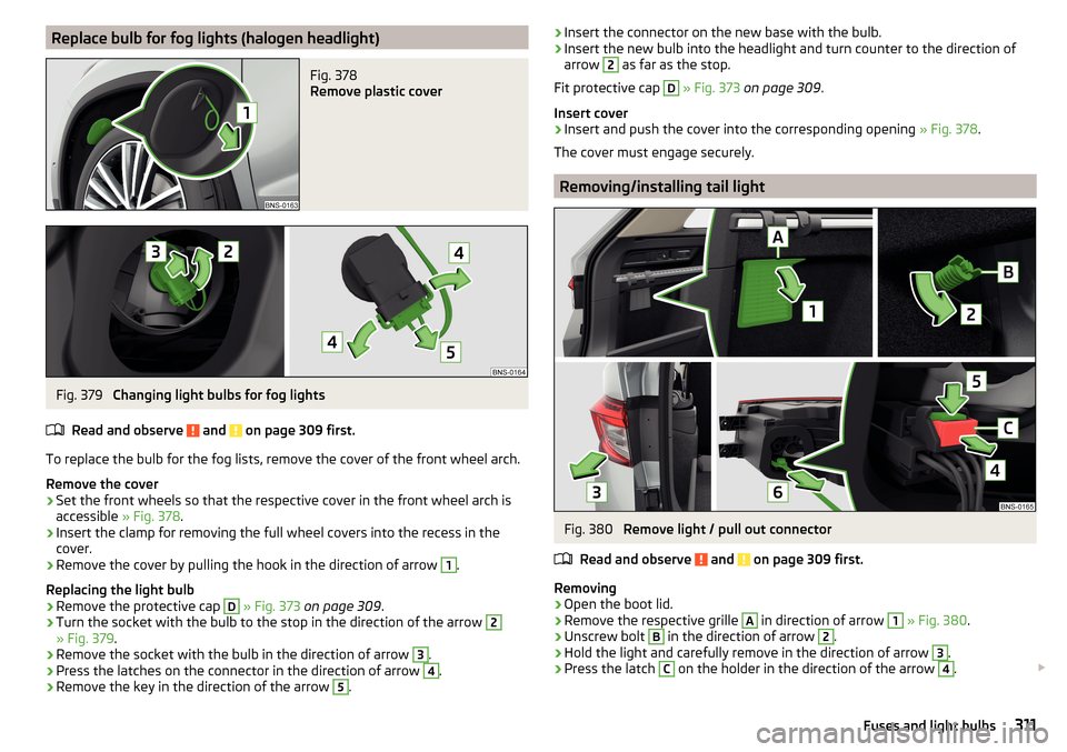
Fig. 379
Changing light bulbs for fog lights
Read and observe
and on page 309 first.
To replace the bulb for the fog lists, remove the cover of the front wheel arch.
Remove the cover
›
Set the front wheels so that the respective cover in the front wheel arch is
accessible » Fig. 378.
›
Insert the clamp for removing the full wheel covers into the recess in the
cover.
›
Remove the cover by pulling the hook in the direction of arrow
1
.
Replacing the light bulb
›
Remove the protective cap
D
» Fig. 373 on page 309 .
›
Turn the socket with the bulb to the stop in the direction of the arrow
2
» Fig. 379.
›
Remove the socket with the bulb in the direction of arrow
3
.
›
Press the latches on the connector in the direction of arrow
4
.
›
Remove the key in the direction of the arrow
5
.
›Insert the connector on the new base with the bulb.›Insert the new bulb into the headlight and turn counter to the direction of
arrow 2
as far as the stop.
Fit protective cap
D
» Fig. 373 on page 309 .
Insert cover
›
Insert and push the cover into the corresponding opening » Fig. 378.
The cover must engage securely.
Removing/installing tail light
Fig. 380
Remove light / pull out connector
Read and observe
and on page 309 first.
Removing
›
Open the boot lid.
›
Remove the respective grille
A
in direction of arrow
1
» Fig. 380 .
›
Unscrew bolt
B
in the direction of arrow
2
.
›
Hold the light and carefully remove in the direction of arrow
3
.
›
Press the latch
C
on the holder in the direction of the arrow
4
.
311Fuses and light bulbs
Page 314 of 344
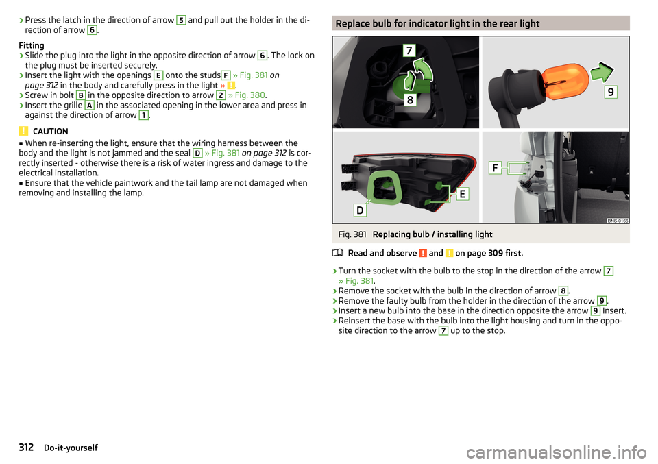
›Press the latch in the direction of arrow 5 and pull out the holder in the di-
rection of arrow 6.
Fitting›
Slide the plug into the light in the opposite direction of arrow
6
. The lock on
the plug must be inserted securely.
›
Insert the light with the openings
E
onto the studs
F
» Fig. 381 on
page 312 in the body and carefully press in the light » .
›
Screw in bolt
B
in the opposite direction to arrow
2
» Fig. 380 .
›
Insert the grille
A
in the associated opening in the lower area and press in
against the direction of arrow
1
.
CAUTION
■ When re-inserting the light, ensure that the wiring harness between the
body and the light is not jammed and the seal D » Fig. 381 on page 312 is cor-
rectly inserted - otherwise there is a risk of water ingress and damage to the
electrical installation.■
Ensure that the vehicle paintwork and the tail lamp are not damaged when
removing and installing the lamp.
Replace bulb for indicator light in the rear lightFig. 381
Replacing bulb / installing light
Read and observe
and on page 309 first.
›
Turn the socket with the bulb to the stop in the direction of the arrow
7
» Fig. 381 .
›
Remove the socket with the bulb in the direction of arrow
8
.
›
Remove the faulty bulb from the holder in the direction of the arrow
9
.
›
Insert a new bulb into the base in the direction opposite the arrow
9
Insert.
›
Reinsert the base with the bulb into the light housing and turn in the oppo-
site direction to the arrow
7
up to the stop.
312Do-it-yourself