check oil SKODA KODIAQ 2016 1.G Owner's Manual
[x] Cancel search | Manufacturer: SKODA, Model Year: 2016, Model line: KODIAQ, Model: SKODA KODIAQ 2016 1.GPages: 344, PDF Size: 58.96 MB
Page 8 of 344
It is the customer's responsibility to prove that it was not the cause.
This ŠKODA warranty does not affect the purchaser's statutory rights from ma-
terials defect liability from the vehicle vendor and other potential claims from
product liability laws.
Mobility warranty
The mobility warranty provides a sense of security when travelling in your ve-
hicle.
If your vehicle breaks down on the road due to an unexpected defect, services
can be rendered under you mobility warranty to ensure that you remain mo-
bile. These services include: breakdown call at breakdown location and towing
away to ŠKODA service partner, technical assistance on the phone or starting-
up at the location of breakdown.
If your vehicle is not repaired on the same day, the ŠKODA Service Partner may
provide further services as required, such as replacement transportation (bus,
train etc.) or a courtesy vehicle etc.
More information regarding terms and conditions for the provision of a mobility
warranty for your vehicle can be obtained from your ŠKODA Partner. They will
also provide you with detailed terms and conditions for the mobility warranty
with respect to your vehicle. In the event that there is no mobility warranty
coverage available for your vehicle, you should check with any ŠKODA Service
Partner about the possibility of a subsequent agreement.
Optional ŠKODA extended warranty
If you opted for a ŠKODA extended warranty when purchasing your new car,
the two-year ŠKODA warranty with regards to all free warranty repairs is ex-
tended by the period you chose or until the chosen mileage limit has been
reached, whichever occurs first.
The previously mentioned paint warranty and the warranty against rust perfo-
ration are unaffected by the ŠKODA extended warranty.
The ŠKODA extended warranty does not apply to external and internal foils.
The information on the detailed conditions of the ŠKODA extended warranty is
provided by your ŠKODA partner.
Note
The ŠKODA extended warranty is only available in some countries.6Liability for defects and ŠKODA warranty for new cars
Page 12 of 344
Structure of the Owner´s Manual and further
information
Structure of the manual
The Owner's Manual is hierarchically divided into the following areas.
■ Paragraph (e.g. Operating instructions) - the title of the paragraph is always
indicated on the lower left-hand side ■ Main chapter (e.g. Checking and refilling) - the title of the main chapter is
always indicated on the lower right-hand side ■ Chapter (e.g. Engine oil)
■ Introductory information
- Module overview within the chapter, in-
troductory information about the chapter content and, where appropri-
ate, information relevant to the whole chapter
■ Module (e.g. Checking and refilling)
Information search
When searching for information in the Owner´s Manual, we recommend using
the Index at the end of the Owner's Manual.
Direction indications
All direction indications such as “left”, “right”, “front”, “rear” relate to the for- ward direction of travel of the vehicle.
Units
The volume, weight, speed and length data are given in metric units, unless
otherwise indicated.
Display
In this Owner's Manual, the MAXI DOT display is used as the display in the in-
strument cluster unless otherwise stated.
Emergency assistance
In the case of a breakdown, the required breakdown service contact informa- tion can be found in the following locations.
▶ Contact information from ŠKODA Partner (e.g. window sticker)
▶ Infotainment (Phone - breakdown service / information service menu)
▶ Mobile application ŠKODA
▶ ŠKODA websites10Structure of the Owner´s Manual and further information
Page 14 of 344
Safety
Passive Safety
General information
Introduction
This chapter contains information on the following subjects:
Before setting off
12
Driving safety
12
This section of the manual includes important information on the subject of
passive safety. We have combined everything here which you should be famili-
ar with, for example, regarding seat belts, airbags, safety of children and any-
thing similar.
Other important safety information can also be found in the following chapters
of this Owner´s Manual. The Owner´s Manual should therefore always be in
the vehicle.
Before setting off
For your own safety and the safety of the people travelling with you, please
pay attention to the following points before setting off.
▶ Check the function of the lighting and turn signal systems.
▶ Check the function of the wipers and check the wiper blades for wear. Check
the windscreen washer fluid level.
▶ Ensure that all of the windows offer good visibility to the outside.
▶ Adjust the rear-view mirror so that vision to the rear is guaranteed. Ensure
that the mirrors are not covered.
▶ Check the tyre inflation pressure.
▶ Check the engine oil, brake fluid and coolant level.
▶ Secure all items of luggage.
▶ Do not exceed the permissible axle loads and permissible gross weight of the
vehicle.
▶ Close all doors as well as the bonnet and boot lid.
▶ Ensure that no objects can obstruct the pedals.
▶
Protect children by using a suitable child seat » page 23, Transporting chil-
dren safely .
▶ Adopt the correct seated position. Instruct your passengers to assume the
correct seated position » page 12, Correct and safe seated position .
Driving safety
In the interests of traffic safety, the following information must be observed. ▶ Do not become distracted from concentrating on the traffic situation, (e.g. by
your passengers or mobile phone calls).
▶ Never drive when your driving ability is impaired, (e.g. due to medication, al-
cohol or drugs).
▶ Keep to the traffic regulations and the permissible speed limit.
▶ Always adjust the driving speed to the road, traffic and weather conditions.
▶ Take regular breaks on long journeys (at least every two hours).
Correct and safe seated position
Introduction
This chapter contains information on the following subjects:
Driver’s correct seated position
13
Adjusting the steering wheel position
13
Passenger’s correct seating position
14
Passengers’ correct seating position on the rear seats
14
Always assume the correct seated position before setting off and do not
change this position while driving. Also advise your passengers to adopt the
correct seated position and not to change this position while the car is moving.
The following list contains instructions for the Passenger which, if not ob-
served, may cause serious injuries or death. ▶ Do not lean against the dash panel.
▶ Do not put your feet on the dash panel.
The following list contains instructions for all Passengers which, if not ob-
served, may cause serious injuries or death.
▶ Do not sit only on the front part of the seat.
▶ Do not sit facing to the side.
▶ Do not lean out of the window.
▶ Do not put your limbs out of the window.
▶ Do not put your feet on the seat cushion.
12Safety
Page 18 of 344
WARNING (Continued)■No two persons (also not children) should ever use a single seat belt to-
gether.■
The lock tongue should only be inserted into the lock which is the correct
one for your seat. Wrong use of the safety belt will reduce its capacity to
protect and the risk of injury increases.
■
Many layers of clothing and loose clothing (e. g. a winter coat over a jack-
et) do not allow you to be correctly seated and impairs proper operation of
the seat belts.
■
Do not use clamps or other objects to adjust seat belts (e.g. for shorten-
ing the belts for smaller persons).
■
The seat belts for second and third row of seats can only fulfil their func-
tion reliably if the rear seat backrests are correctly locked into position
» page 80 .
WARNINGInformation on the care and maintenance of safety belts■The belt webbing must always be kept clean. Soiled belt webbing may im-
pair the proper operation of the inertia reel » page 273.■
The seat belts must not be removed or changed in any way. Do not at-
tempt to repair the seat belts yourself.
■
Check the condition of all the seat belts on a regular basis. If parts of the
belt system become damaged (e.g. the belt webbing, the belt connections,
the inertia reel, the locking part etc.), the respective seat belt must be re-
placed by a specialist garage immediately.
■
Seat belts which have been subjected to stress in an accident must be re-
placed by a specialist garage. The anchorage points for the belts should al-
so be checked.
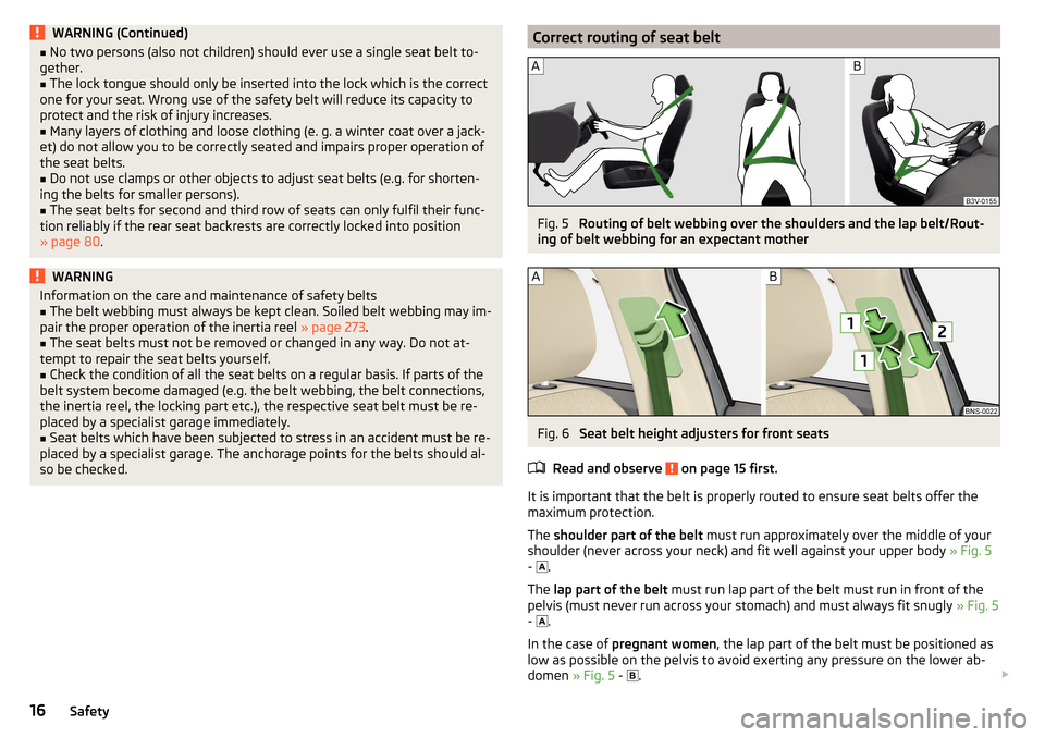
Correct routing of seat beltFig. 5
Routing of belt webbing over the shoulders and the lap belt/Rout-
ing of belt webbing for an expectant mother
Fig. 6
Seat belt height adjusters for front seats
Read and observe
on page 15 first.
It is important that the belt is properly routed to ensure seat belts offer the
maximum protection.
The shoulder part of the belt must run approximately over the middle of your
shoulder (never across your neck) and fit well against your upper body » Fig. 5
-
.
The lap part of the belt must run lap part of the belt must run in front of the
pelvis (must never run across your stomach) and must always fit snugly » Fig. 5
-
.
In the case of pregnant women , the lap part of the belt must be positioned as
low as possible on the pelvis to avoid exerting any pressure on the lower ab-
domen » Fig. 5 -
.
16Safety
Page 42 of 344
Coolant temperature too high Illumi-
nates
Engine overheat. Stop! Log book!ENGINE OVERHEAT STOP
▶ Stop the vehicle, switch off the engine and let it cool.
▶ Continue your journey only after the warning light
has disappeared.
Engine oil pressure
Read and observe
on page 34 first.
flashes – the engine oil pressure is too low.
▶ Stop the vehicle, switch off the engine, and check the engine oil level.
▶ If the warning light flashes,
stop driving , even if the oil level is OK! Also do
not leave the engine running at an idling speed.
▶ Seek help from a specialist garage.
CAUTION
If it is not possible to top up with engine oil under the given conditions, stop
driving - there is a risk of engine damage! Switch off the engine and seek as-
sistance from a specialist garage.
Engine oil level
Read and observe
on page 34 first.
Engine oil level too low
Illumi-
nates
Oil level: add oil!ADD OIL
▶ Stop the vehicle, switch off the engine, and check the engine oil level, top up
if necessary.
The warning light will go out if the bonnet is left open for more than 30 sec-
onds. If the engine oil is not replenished, the warning light will come on again
after driving about 100 km.
Engine oil level too high
Illumi-
nates
Reduce oil level!OIL LEVEL TOO HIGH
▶ Stop the vehicle, switch off the engine, and check the engine oil level.
▶ If the oil level is too high, you can driven on, exercising appropriate caution.
Seek assistance from a specialist garage immediately.
Fault on the engine oil level sensor Illumi-
nates
Oil sensor: Workshop!OIL SENSOR WORKSHOP
▶ You can drive on, exercising appropriate caution. Seek assistance from a spe-
cialist garage immediately.
CAUTION
If it is not possible to top up with engine oil under the given conditions, stop
driving - there is a risk of engine damage! Switch off the engine and seek as-
sistance from a specialist garage.
AdBlue ®
(diesel engine)
Read and observe
on page 34 first.
AdBlue ®
level too low
Information on the amount of AdBlue ®
to be added is also shown. The values
"min" and "max" stand for the minimum and maximum AdBlue ®
replenishment
amounts.
Illuminates
AdBlue (DEF) refill! Range: ...REFILL ADBLUE (DEF)... RANGE_ ...
The range in the display indicates the distance that can be driven with the re-
maining AdBlue ®
left in the tank.
▶ Add AdBlue ®
» page 277 .
Illumi-
nates
AdBlue (DEF) refill! No start in ...REFILL ADBLUE (DEF)_...NO START IN …
The value in the display indicates the distance that can still be travelled, after
which no engine restart is possible unless AdBlue ®
is added.
▶ Add AdBlue ®
» page 277 .
Illumi-
nates
AdBlue (DEF) refill! Engine start no longer possible.REFILL ADBLUE (DEF)... NO RESTART
It is no longer possible to start the engine.
▶ Add AdBlue ®
» page 277 .
AdBlue ®
fault
Illumi-
nates
Error: AdBlue (DEF). No engine start in ...ADBLUE (DEF) ERROR NO START IN …
40Operation
Page 48 of 344
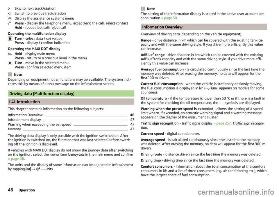
Skip to next track/station
Switch to previous track/station
Display the assistance systems menu
Press - display the telephone menu; accept/end the call; select contact
Hold - repeat last call; reject call
Operating the multifunction display Turn - select data / set values
Press - display / confirm indication
Operating the MAXI DOT display Hold - display main menu
Press - return to a previous level in the menu
Turn - move in the selected menu
Press - confirm selected menu item
Note
Depending on equipment not all functions may be available. The system indi-
cates this by means of a text message on the Infotainment screen.
Driving data (Multifunction display)
Introduction
This chapter contains information on the following subjects:
Information Overview
46
Infotainment display
47
Warning when exceeding the set speed
47
Memory
47
The driving data display is only possible with the ignition switched on. After
the ignition is switched on, the function that was last selected before switch-
ing off the ignition is displayed.
If vehicles with MAXI DOTdisplay do not show the journey data after switching
on the ignition, select the menu item
Journey data
in the main menu and confirm
» page 48 .
The units and the display of some information can be adjusted in Infotainment
by tapping
→
→
Units
.
BBNoteThe setting of the information display is stored in the active user account per-
sonalisation » page 50.
Information Overview
Overview of driving data (depending on the vehicle equipment).
Range - drive distance in km which can be covered with the existing tank ca-
pacity and with the same driving style. If you drive more efficiently this value
can increase.
AdBlue ®
range - drive distance in km which can be covered with the existing
AdBlue ®
tank capacity and with the same driving style. If you drive more effi-
ciently this value can increase.
Average fuel consumption - is calculated continuously since the last time the
memory was deleted. After erasing the memory, no data will appear for the
first 100 m driven.
Current fuel consumption - when the vehicle is stationary or slowly moving,
the fuel consumption is displayed in l/h (--,- km/l appears on models for some
countries).
Oil temperature - if the temperature is lower than 50 °C or if there is a fault in
the system for checking the oil temperature, the symbols are displayed.
Warning when the preset speed is exceeded - allows the setting of a speed
limit where, if exceeded, an acoustic warning signal and a warning message
appears on the display of the instrument cluster.
Traffic sign recognition - traffic signs display » page 257, Traffic sign recogni-
tion .
Current speed - digital speedometer.
Average speed - is calculated continuously since the last time the memory
was deleted. After erasing the memory, no data will appear for the first 300 m
driven.
Driving route - distance driven since the last time the memory was deleted.
Driving time - driving time since the last time the memory was deleted.
Comfort consumers - information about the total consumption of the comfort
consumers in l/h and a list of three consumers (e.g. air conditioning etc.), which
have the largest share of fuel consumption.
46Operation
Page 208 of 344
Brakes and Parking
Introduction
This chapter contains information on the following subjects:
Electric parking brake
206
Auto Hold function
207
Parking
208
The wear of the brake pads is dependent on the operating conditions and driv-
ing style. Under difficult conditions (e.g. urban, sporty driving style) the condi-
tion of the brakes should also be checked by a specialist garage between the
service intervals.
The performance of the brakes can be delayed if the brakes are damp, iced up
in winter or if covered in a layer of salt . The brakes are cleaned and dried by
applying the brakes several times »
.
Corrosion on the brake discs and dirt on the brake pads occur if the vehicle has
been parked for a long period and if you do not make much use of the braking
system. The brakes are cleaned by applying the brakes several times »
.
Before travelling a long distance with a steep gradient , reduce speed and
shift into the next lowest gear. As a result, the braking effect of the engine will
be used, reducing the load on the brakes. If you do have to brake, this should
be carried out at intervals.
Emergency braking display - when an emergency braking is performed, the
automatic flashing of the brake lights are used to alert the traffic behind.
New brake pads must first be “worn in” because these do not initially have the
best possible braking effect. Drive especially carefully for the first 200 km or
so.
A too low brake fluid level can cause faults in the braking system , the warn-
ing light illuminates in the instrument cluster
» page 35,
Brake system
. If
the warning light does not illuminate and an extended stopping distance is re-
quired, then driving should be adapted according to the unknown cause of
fault and restricted braking effect - seek the assistance of a specialist garage
immediately.
The brake booster increases the pressure generated with the brake pedal. The
brake booster only operates when the engine is running.
WARNING■ Greater physical effort is required for braking when the engine is switch-
ed off – risk of accident!■
During the braking procedure on a vehicle with manual transmission,
when the vehicle is in gear and at low revs, press the clutch pedal. Other-
wise, the functionality of the brake system may be impaired – risk of acci-
dent!
■
Do not press the brake pedal if braking is now required. This causes the
brakes to overheat and can also result in a longer braking distance and ex-
cessive wear - risk of accident!
■
Braking for the purpose of drying and cleaning the brake discs should be
carried out only if the traffic conditions permit. Do not place any other road
users in jeopardy.
■
Recommendations for new brake pads have to be observed.
■
When stopping and parking, the parking brake should always be on, oth-
erwise the vehicle could move off - there is the risk of an accident!
■
If a front spoiler, full wheel trim, etc. is mounted retrospectively, it must
be ensured that the air supply to the front wheel brakes is not reduced.
Otherwise, the functionality of the brake system may be impaired – risk of
accident!
Electric parking brake
Fig. 255
Parking brake button
206Driving
Page 217 of 344
Assist systems
General information
Introduction
This chapter contains information on the following subjects:
Radar sensor
215WARNING■ The assistance systems only serve to support the driver and do not re-
lieve the driver of the responsibility for driving the vehicle.■
The increased safety provision, as well as the increased occupant protec-
tion provided by the assistance systems must not tempt you to take risks -
risk of accident!
■
Adjust the speed and driving style to the current visibility, weather, road
and traffic conditions.
■
The assistance systems have physical and system-related limitations. For
this reason, the driver may experience some undesired or delayed system
responses in certain situations. You should therefore always be alert and
ready to intervene!
■
Only enable, disable or set the assistance systems when you have the car
fully under control, in every traffic situation - risk of accident!
Radar sensor
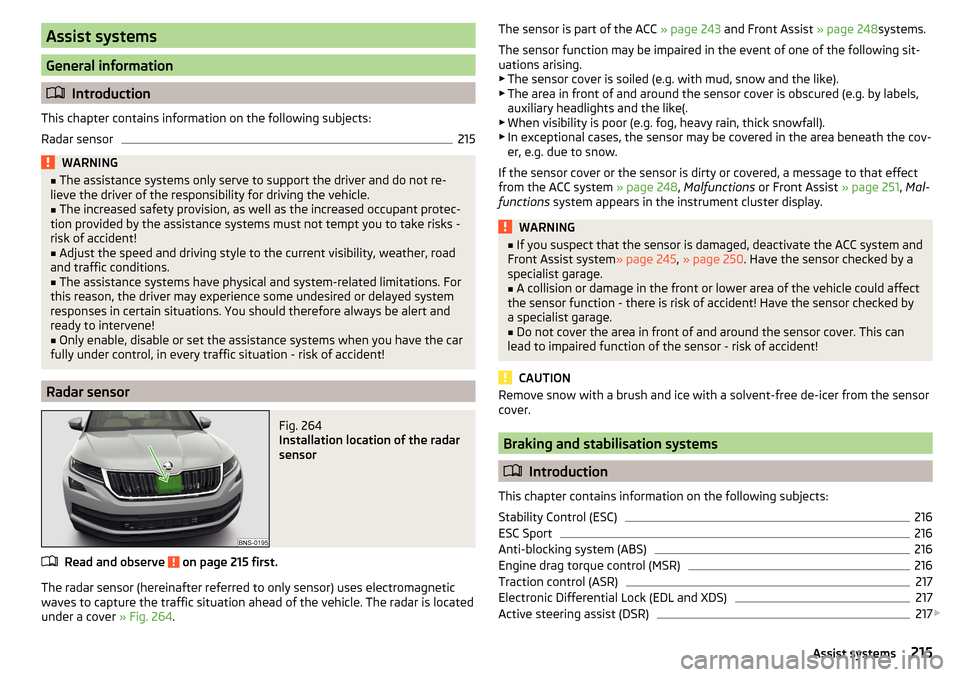
Fig. 264
Installation location of the radar
sensor
Read and observe on page 215 first.
The radar sensor (hereinafter referred to only sensor) uses electromagnetic
waves to capture the traffic situation ahead of the vehicle. The radar is located
under a cover » Fig. 264.
The sensor is part of the ACC » page 243 and Front Assist » page 248systems.
The sensor function may be impaired in the event of one of the following sit-
uations arising. ▶ The sensor cover is soiled (e.g. with mud, snow and the like).
▶ The area in front of and around the sensor cover is obscured (e.g. by labels,
auxiliary headlights and the like(.
▶ When visibility is poor (e.g. fog, heavy rain, thick snowfall).
▶ In exceptional cases, the sensor may be covered in the area beneath the cov-
er, e.g. due to snow.
If the sensor cover or the sensor is dirty or covered, a message to that effect
from the ACC system » page 248, Malfunctions or Front Assist » page 251, Mal-
functions system appears in the instrument cluster display.WARNING■
If you suspect that the sensor is damaged, deactivate the ACC system and
Front Assist system » page 245, » page 250 . Have the sensor checked by a
specialist garage.■
A collision or damage in the front or lower area of the vehicle could affect
the sensor function - there is risk of accident! Have the sensor checked by
a specialist garage.
■
Do not cover the area in front of and around the sensor cover. This can
lead to impaired function of the sensor - risk of accident!
CAUTION
Remove snow with a brush and ice with a solvent-free de-icer from the sensor
cover.
Braking and stabilisation systems
Introduction
This chapter contains information on the following subjects:
Stability Control (ESC)
216
ESC Sport
216
Anti-blocking system (ABS)
216
Engine drag torque control (MSR)
216
Traction control (ASR)
217
Electronic Differential Lock (EDL and XDS)
217
Active steering assist (DSR)
217
215Assist systems
Page 229 of 344
Rear View Camera
Introduction
This chapter contains information on the following subjects:
Operating principle
227
Activation/deactivation
228
Function surfaces
228
Orientation lines and lane
228
Mode - traverse parking
229
Mode - parallel parking
229
Mode - driving up to a trailer / distance monitoring
230
Mode - monitor the area behind the vehicle
230
The rear view camera (following as system) helps the driver when parking and
manoeuvring by displaying the area behind the vehicle on Infotainment screen
(hereinafter only known as screen).
There are four modes available for different situations during the park and ma-
noeuvring action. The mode change is carried out using the function surfaces
on the screen » page 228.
WARNING■
The general information relating to the use of assistance systems must
be observed » page 215, in section Introduction .■
The system detects obstacles. The display of the auxiliary boxes and lines
is independent of the actual vehicle environment. The driver must judge for
themselves whether the vehicle can park safely in the selected parking
space.
■
The camera may not be soiled or obscured, otherwise the system function
will be significantly affected - there is a risk of accident. For information on
cleaning » page 271 .
CAUTION■
The camera image is distorted by contrast with eyesight. For this reason, the
screen display is only of limited use for estimating distances to following vehi-
cles.■
Some items, such as thin posts, chain link fences, grilles or uneven road sur-
faces may not be properly displayed in terms of screen resolution.
■
In a crash or damage the vehicle's rear camera can possibly deviate from the
correct position. If this is the case, have the sensor checked by a specialist ga-
rage.
Note
The camera is equipped with a cleaning system » page 75. The spraying is car-
ried out automatically when the rear window is sprayed.
Operating principle
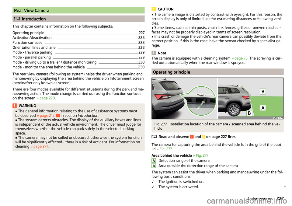
Fig. 277
Installation location of the camera / scanned area behind the ve-
hicle
Read and observe
and on page 227 first.
The camera for capturing the area behind the vehicle is in the grip of the bootlid » Fig. 277 .
Area behind the vehicle » Fig. 277
Detection range of the camera
Area outside the detection range of the camera
The system can assist the driver when parking and manoeuvring under the fol- lowing basic conditions.
The ignition is switched on.
The system is activated.
AB227Assist systems
Page 233 of 344
WARNING■The general information relating to the use of assistance systems must
be observed » page 215, General information .■
The system detects obstacles. The auxiliary boxes and lines are displayed
by the system, regardless of the area around the vehicle. The driver must
judge for themselves whether the vehicle can park safely in the selected
parking space.
■
The camera may not be soiled or obscured, otherwise the system function
will be significantly affected - there is a risk of an accident. For information
on cleaning » page 271.
CAUTION
■
The camera image is distorted by contrast with eyesight. For this reason, the
screen display is only of limited use for estimating distances to following vehi-
cles.■
Objects that are located directly beside the corners of the vehicle may be
outside the field of view of the cameras and may therefore not be displayed on
the screen.
■
Some items, such as thin posts, chain link fences, grilles or uneven road sur-
faces may not be properly displayed in terms of screen resolution.
■
In a vehicle damaged in the area of one of the cameras, the respective cam-
era can possibly deviate from the correct position. If this is the case, have the
sensor checked by a specialist garage.
CAUTION
The objects shown on the screen can be closer or even further away than they
appear. This is especially the case in the following situations.■
Protruding objects, such as the rear of a truck and the like.
■
When driving from a horizontal surface into a slope or a depression.
■
When driving from a slope or a depression onto a horizontal surface.
Operating principleFig. 284
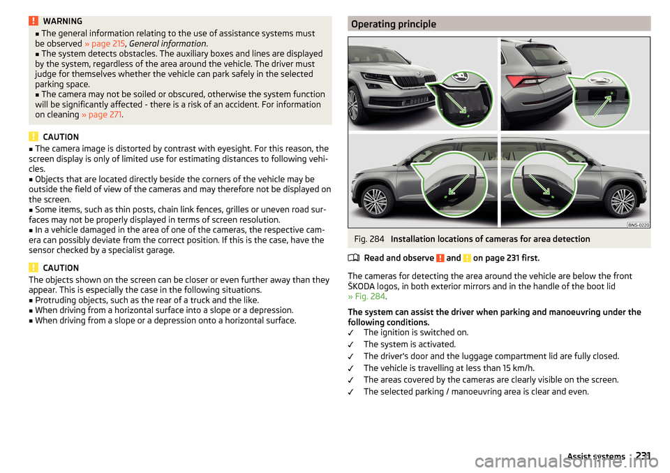
Installation locations of cameras for area detection
Read and observe
and on page 231 first.
The cameras for detecting the area around the vehicle are below the front
ŠKODA logos, in both exterior mirrors and in the handle of the boot lid
» Fig. 284 .
The system can assist the driver when parking and manoeuvring under the
following conditions. The ignition is switched on.
The system is activated.
The driver's door and the luggage compartment lid are fully closed.
The vehicle is travelling at less than 15 km/h.
The areas covered by the cameras are clearly visible on the screen.
The selected parking / manoeuvring area is clear and even.
231Assist systems