SKODA OCTAVIA 2006 Owner´s Manual
Manufacturer: SKODA, Model Year: 2006, Model line: OCTAVIA, Model: SKODA OCTAVIA 2006Pages: 218, PDF Size: 5.48 MB
Page 51 of 218
CAUTION
■ In cold temperatures and during the winter, check before the journey or before
switching on the ignition that the wiper blades are not frozen to the windscreen.
If the windscreen wipers are switched on when the blades are frozen to the
windscreen, this may damage both the blades and windscreen wiper motor!
■ If the ignition is switched off while the windscreen wipers are switched on, the
windscreen wipers will continue wiping in the same mode after the ignition is
turned back on. The windscreen wipers could freeze up in cold temperatures be-
tween the time the ignition was turned off and when it was turned back on again.
■ Carefully detach frozen wiper blades from the front or rear window.
■ Remove snow and ice from the windscreen wipers before driving.
■ If the windscreen wipers are handled carelessly, there is a risk of damage to the
windscreen.
■ Replace the windscreen wiper blades once or twice a year for safety reasons.
These can be purchased from a ŠKODA Service Partner.
■ The ignition must not be switched on if the front windscreen wiper arms are fol-
ded out. The wiper blades would move back into their rest position and while do-
ing so damage the paintwork of the bonnet. Note
■ If the slower 2
» Fig. 35 on page 49 or the faster 3
wiper setting is switched
on and the vehicle speed decreases to below 4 km/h, the lower wiper step is
switched on automatically. At a speed increase of more than 8 km/h the previous
wiper setting is established again.
■ If there is an obstacle on the windscreen, the wiper will try to push away the
obstacle. If the obstacle continues to block the wiper, the wiper stops automati-
cally after 5 attempts to eliminate the obstacle, in order to avoid a damage to the
wiper. Remove the the obstacle and switch the wiper on again. ■ The windscreen washer nozzles for the windscreen are heated when the en-
gine is running and the outside temperature is less than approx. +10
°C.
■ The content of the windscreen washer fluid reservoir is 3 litres. On vehicles fit-
ted with the headlight cleaning system, the volume is 5.5
litres. On vehicles fitted
with auxiliary heating, the content of the windscreen wiper reservoir is 4.5 litres.
■ The wiper blades should be cleaned on a regular basis with a windscreen clean-
er to avoid any smears. The wiper blades should be cleaned with a sponge or
cloth if they are heavily soiled by insect residues, for example. Ð Activating the windscreen wipers and washers
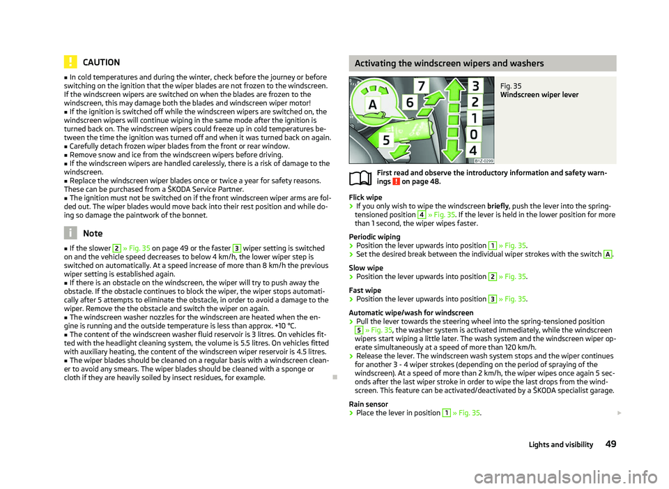
Fig. 35
Windscreen wiper lever
First read and observe the introductory information and safety warn-
ings on page 48.
Flick wipe
›
If you only wish to wipe the windscreen
briefly, push the lever into the spring-
tensioned position 4
» Fig. 35. If the lever is held in the lower position for more
than 1 second, the wiper wipes faster.
Periodic wiping
› Position the lever upwards into position 1
» Fig. 35.
› Set the desired break between the individual wiper strokes with the switch A
.
Slow wipe
› Position the lever upwards into position 2
» Fig. 35.
Fast wipe
› Position the lever upwards into position 3
» Fig. 35.
Automatic wipe/wash for windscreen
› Pull the lever towards the steering wheel into the spring-tensioned position 5
» Fig. 35, the washer system is activated immediately, while the windscreen
wipers start wiping a little later. The wash system and the windscreen wiper op-
erate simultaneously at a speed of more than 120
km/h.
› Release the lever. The windscreen wash system stops and the wiper continues
for another 3 - 4 wiper strokes (depending on the period of spraying of the
windscreen). At a speed of more than 2 km/h, the wiper wipes once again 5 sec-
onds after the last wiper stroke in order to wipe the last drops from the wind-
screen. This feature can be activated/deactivated by a
ŠKODA specialist garage.
Rain sensor
› Place the lever in position 1
» Fig. 35.
£
ä
49
Lights and visibility
Page 52 of 218
›
The sensitivity of the sensor can be set individually with the switch A
.
Wiping the rear window pane
› Push the lever away from the steering wheel into position 6
» Fig. 35 and the
windscreen wiper will operate every 6
seconds.
Automatic wipe/wash for the rear window
› Press the lever completely away from the steering wheel into the spring-ten-
sioned position 7
» Fig. 35, the washer system is activated immediately, while
the windscreen wiper starts wiping a little later. The wiper and washer system
will operate as long as the lever is held in this position.
› Release the lever. The washer system stops and the wiper continues for anoth-
er 2 to 3
wiper strokes (depending on the duration of the spraying process). The
lever will stay in position after releasing it 6
.
Switching windscreen wipers off
› Move the lever back into the home position 0
» Fig. 35.
Winter position
If the windscreen wipers are in rest position, they cannot be folded out from the
windscreen. For this reason we recommend adjusting the windscreen wipers in
winter so that they can be folded out from the windscreen easily.
This rest position is set as follows:
› Switch on the windscreen wipers.
› Switch off the ignition. The windscreen wipers remain in the position in which
they were when switching off the ignition.
The service position can also be used as a winter position » page 51.ÐAutomatic rear window wiper (Combi)
First read and observe the introductory information and safety warn-
ings on page 48.
If the windscreen wiper is in position 2
» Fig. 35 on page 49 or 3
the rear win-
dow is wiped every 30 or 10 seconds if the vehicle's speed exceeds 5
km/h.
When the rain sensor is active (the lever is in the position 1
) the function is only
active if the windscreen wipers operate in continuous mode (no break between
each wiping process). ä Activation/deactivation
The function of the automatic rear window wiper is activated/deactivated in the
information display in the menu:
■ Settings
■ Lights & Vision
■ Rear wiper Ð Headlight cleaning system
First read and observe the introductory information and safety warn-
ings on page 48.
The headlights are being cleaned after the windscreen has been sprayed for the
first time and fifth time, the low beam or main beam are switched on and the
windscreen wiper lever was held in the position 5
» Fig. 35 on page 49 for about
1 second.
The headlight washer nozzles are moved forward out of the bumper by the water
pressure for cleaning the headlights.
You should remove stubborn dirt (such as insect residues) from the headlight len-
ses at regular intervals, for example when refuelling. The following guidelines
must be observed » page 151, Headlight lenses.
To ensure the proper operation of the cleaning system during the winter, any
snow should be removed from the washer nozzle fixtures and ice should be
cleared with a de-icing spray. CAUTION
Never remove the nozzles from the headlight cleaning system by hand - risk of
damage! Ð
ä
50 Using the system
Page 53 of 218
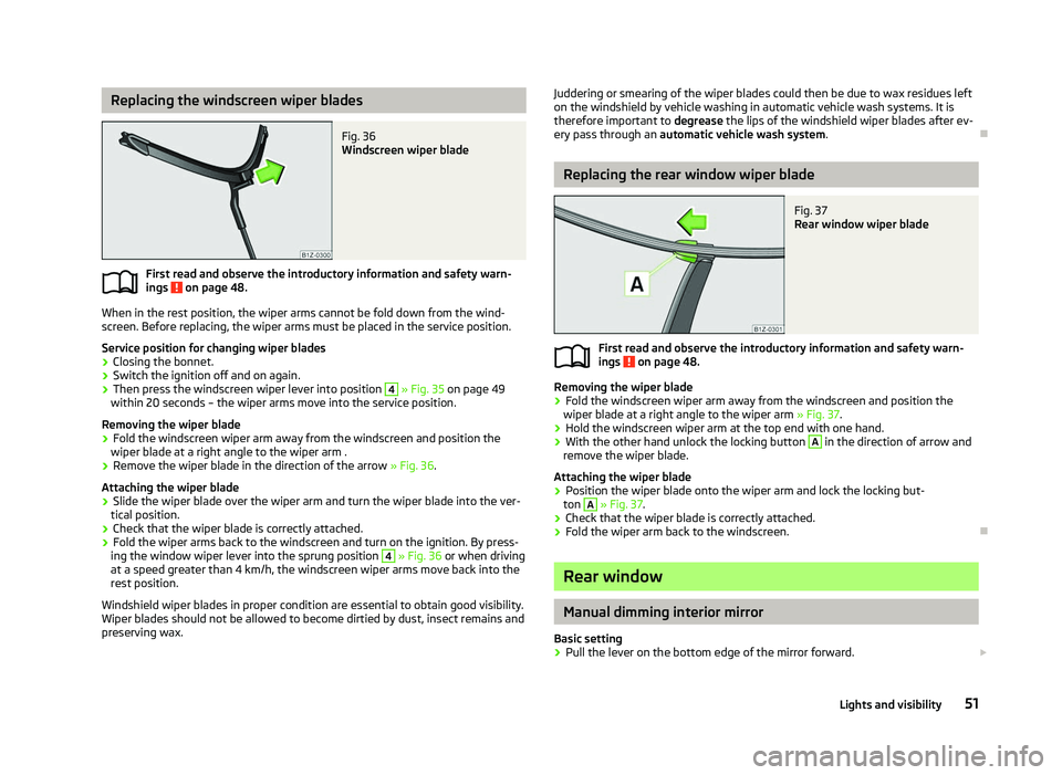
Replacing the windscreen wiper blades
Fig. 36
Windscreen wiper blade
First read and observe the introductory information and safety warn-
ings on page 48.
When in the rest position, the wiper arms cannot be fold down from the wind-
screen. Before replacing, the wiper arms must be placed in the service position.
Service position for changing wiper blades
› Closing the bonnet.
› Switch the ignition off and on again.
› Then press the windscreen wiper lever into position 4
» Fig. 35 on page
49
within 20 seconds – the wiper arms move into the service position.
Removing the wiper blade
› Fold the windscreen wiper arm away from the windscreen and position the
wiper blade at a right angle to the wiper arm .
› Remove the wiper blade in the direction of the arrow
» Fig. 36.
Attaching the wiper blade
› Slide the wiper blade over the wiper arm and turn the wiper blade into the ver-
tical position.
› Check that the wiper blade is correctly attached.
› Fold the wiper arms back to the windscreen and turn on the ignition. By press-
ing the window wiper lever into the sprung position 4
» Fig. 36 or when driving
at a speed greater than 4
km/h, the windscreen wiper arms move back into the
rest position.
Windshield wiper blades in proper condition are essential to obtain good visibility.
Wiper blades should not be allowed to become dirtied by dust, insect remains and
preserving wax.
ä
Juddering or smearing of the wiper blades could then be due to wax residues left
on the windshield by vehicle washing in automatic vehicle wash systems. It is
therefore important to degrease the lips of the windshield wiper blades after ev-
ery pass through an automatic vehicle wash system .Ð Replacing the rear window wiper blade
Fig. 37
Rear window wiper blade
First read and observe the introductory information and safety warn-
ings on page 48.
Removing the wiper blade
›
Fold the windscreen wiper arm away from the windscreen and position the
wiper blade at a right angle to the wiper arm » Fig. 37.
› Hold the windscreen wiper arm at the top end with one hand.
› With the other hand unlock the locking button A
in the direction of arrow and
remove the wiper blade.
Attaching the wiper blade
› Position the wiper blade onto the wiper arm and lock the locking but-
ton A
» Fig. 37
.
› Check that the wiper blade is correctly attached.
› Fold the wiper arm back to the windscreen. Ð Rear window
Manual dimming interior mirror
Basic setting
› Pull the lever on the bottom edge of the mirror forward.
£
ä
51
Lights and visibility
Page 54 of 218
Dimming mirror
›
Push the lever on the bottom edge of the mirror backwards. ÐAutomatic dimming interior mirror
Fig. 38
Automatic dimming interior mir-
ror
Switching on automatic dimming › Press the button B
» Fig. 38, the warning light A
lights up.
Switching off automatic dimming
› Press the button B
» Fig. 38 again, the warning light A
goes out.
If the automatic dimming is switched on, the mirror dims automatically depend-
ing on the light striking the mirror from the rear. The mirror has no lever on the
bottom edge of the mirror. After the reverse gear is engaged, the mirror always
moves back into the normal position. WARNING
The display lighting on the external navigation device may cause the automat-
ic dimming interior mirror to malfunction – risk of accident. For this reason, do
not fix any external navigation systems in the proximity of the automatic dim-
ming interior mirror. Note
■ Automatic mirror dimming operates only properly if the sun screen for the rear
window is not in use or the light striking the rear of the interior rear-view mirror is
not affected by other objects. ■ Do not affix any stickers in front of the light sensor, so that they do not impair
the automatic dimming function or put it out of operation. ■ If the automatic interior mirror dimming is switched off, the exterior mirror dim-
ming is also switched off. Ð Exterior mirror
Fig. 39
Inner part of door: Rotary knob
Adjust the rear mirror before commencing to drive so that there is a clear view to
the rear.
Heating of the external mirror
› Place the rotary knob into the position
» Fig. 39.
The exterior mirror heater only operates when the engine is running and up to an
outside temperature of +20 °C.
Adjusting left and right exterior mirrors simultaneously
› Place the rotary knob into the position
. The movement of the mirror surface is
identical to the movement of the rotary knob.
The adjustment of both mirrors simultaneously or each individual mirror is possi-
ble in the Information display » page 16 in the menu point Mirror adjust. .
Adjusting the right-hand exterior mirror
› Place the rotary knob into the position
. The movement of the mirror surface is
identical to the movement of the rotary knob. £
52 Using the system
Page 55 of 218
Switching off operating control
›
Place the rotary knob into the position
.
Folding-in both of the exterior mirrors with the rotary knob
› Place the rotary knob into the position
.
The mirrors are folded back into the driving position after the rotary knob is
turned from the position to a different one.
It is only possible to fold in both exterior mirrors when the ignition is switched on
and at a speed of up to 15
km/h.
Folding-in both of the exterior mirrors using the remote control key
› If all of the windows are closed, press and hold the lock button 3
» Fig. 13 on
page 30 on the radio remote control for approx. 2
seconds.
The exterior mirrors are folded back into the driving position after opening the
door or switching on the ignition.
Tilting surface of front passenger exterior mirror
On vehicles fitted with the memory function for the driver seat, the surface of the
mirror tilts down slightly when the reverse gear is engaged and the rotary knob is
in the position » Fig. 39. This provides an aid in seeing the kerb of the pavement
when parking the car.
The mirror returns into its initial position, after the rotary knob is moved out of
the position and put into another position or if the speed is more than 15 km/h.
Memory function for exterior mirrors
On vehicles fitted with a memory function for the driver seat, the relevant setting
for the exterior mirrors is also stored automatically when the seat position is stor-
ed » page 55. WARNING
■ Convex (curved outward) exterior mirrors increase the field of vision. They
do, however, make objects appear smaller in the mirror. These mirrors are
therefore only of limited use for estimating distances to the following vehi-
cles.
■ Whenever possible use the interior mirror for estimating the distances to
the following vehicles. CAUTION
Never mechanically fold in or fold back the exterior mirrors with the fold-in func-
tion by hand as this will damage the electric drive. Note
■ If the exterior mirrors were folded in using the rotary knob, they can only be fol-
ded back into the driving position using the rotary knob. ■ If the exterior mirrors were folded in using the remote control key and if the ro-
tary knob was in the fold-in position before the ignition was switched on, the mir-
rors will remain in the fold-in position the next time the ignition is switched on.
The mirrors are folded back into the driving position after the rotary knob is
turned from the position to a different one.
■ Do not touch the surface of the exterior mirrors if the exterior mirror heater is
switched on. ■ If the power setting function fails at any time, the exterior mirrors can be set by
hand by pressing on the edge of the mirror surface. ■ Contact your ŠKODA specialist garage if there is a fault with the power setting
of the exterior mirrors. Ð Automatic dimming exterior mirror on the driver's side
The exterior mirror on the driver's side is dimmed together with the interior mir-
ror. If the automatic dimming is switched on, the mirror dims automatically de-
pending on the light striking the mirror from the rear.
After the reverse gear is engaged, the mirror always moves back into the normal
(not dimmed) position. Note
■ Automatic mirror dimming operates only properly if the sun screen for the rear
window is not in use or the light striking the rear of the interior rear-view mirror is
not affected by other objects. ■ Do not affix any stickers in front of the light sensor, so that they do not impair
the automatic dimming function or put it out of operation. ■ If the automatic interior mirror dimming is switched off, the exterior mirror dim-
ming is also switched off. Ð 53
Lights and visibility
Page 56 of 218
Seats and Stowage
Front seats
ä
Introduction
This chapter contains information on the following subjects:
Manually adjusting the front seats 55
Adjusting front seats electrically 55
Storing setting 56
Assigning the remote control key to the memory button 56
Retrieving the seat and exterior mirror settings 56
The driver's seat should be adjusted in such a way that the pedals can be fully
pressed to the floor with slightly bent legs.
The seat backrest on the driver's seat should be adjusted in such a way that the
upper point of the steering wheel can be easily reached with slightly bent arms.
Correct adjustment of the seats is particularly important for:
› safely and quickly reaching the controls;
› a relaxed, fatigue-free body position;
› achieving the maximum protection offered by the seat belts and the airbag
system. WARNING
■ Only adjust the driver's seat when the vehicle is stationary - risk of accident!
■ Caution when adjusting the seat! You may suffer injuries or bruises as a re-
sult of adjusting the seat without paying proper attention. ■ As the electric front seats can also be adjusted when the ignition is switch-
ed off (even when the ignition key is withdrawn), never leave children unat-
tended in the car. ■ The seat backrests must not be angled too far back when driving otherwise
this will affect proper operation of the seat belts and of the airbag system -
risk of injury! ■ Never carry more people than the number of seats in the vehicle. WARNING (Continued)
■ Each occupant must correctly fasten the seat belt belonging to the seat.
Children must be fastened » page 135, Transporting children safely with a
suitable restraint system.
■ The front seats and the head restraints must always be adjusted to match
the body size of the seat occupant as well as the seat belts must always be
correctly fastened in order to provide an optimal protection for you and your
occupants.
■ Always keep your feet in the footwell when the car is being driven - never
place your feet on the instrument panel, out of the window or on the surfaces
of the seats. This is particularly important for the front seat passenger. You
will be exposed to increased risk of injury if it becomes necessary to apply the
brake or in the event of an accident. If an airbag is deployed, you may suffer
fatal injuries when adopting an incorrect seated position!
■ It is important for the driver and front passenger to maintain a distance of at
least 25 cm from the steering wheel or dash panel. Not maintaining this mini-
mum distance will mean that the airbag system will not be able to properly
protect you - hazard!
■ Ensure that there are no objects in the footwell as they may get caught be-
hind the pedals when driving or applying the braking. You would then no lon-
ger be able to operate the clutch, brake or accelerate.
■ Do not transport any objects on the front passenger seat except objects
(e.g. child safety seat) provided for this purpose - risk of accident! Note
After a certain time, play can develop within the adjustment mechanism of the
backrest angle. Ð
54 Using the system
Page 57 of 218
Manually adjusting the front seats
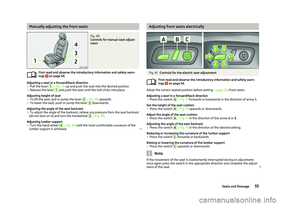
Fig. 40
Controls for manual seat adjust-
ment
First read and observe the introductory information and safety warn-
ings on page 54.
Adjusting a seat in a forward/back direction
›
Pull the lever 1
» Fig. 40 up and push the seat into the desired position.
› Release the lever 1
and push the seat until the lock clicks into place.
Adjusting height of seat
› To lift the seat, pull or pump the lever 2
» Fig. 40 upwards.
› To lower the seat, push or pump the lever 2
downwards.
Adjusting the angle of the seat backrest
› To adjust the angle of the backrest, relieve any pressure from the seat backrest
(do not lean on it) and turn the handwheel 3
» Fig. 40.
Adjusting lumbar support
› Turn the hand wheel 4
» Fig. 40
until the most comfortable curvature of the
lumbar support is achieved. Ð
ä Adjusting front seats electrically
Fig. 41
Controls for the electric seat adjustment
First read and observe the introductory information and safety warn-
ings on page 54.
Adopt the correct seated position before setting
» page 54, Front seats.
Adjusting a seat in a forward/back direction
› Press the switch A
» Fig. 41
forwards or backwards in the direction of arrow 1.
Set the height of the seat cushion
› Press the switch A
»
Fig. 41
upwards or downwards.
Adjust the angle of the seat cushion
› Press the switch A
»
Fig. 41
in the direction of the arrow 2 or 3.
Adjusting the angle of the seat backrest
› Press the switch B
»
Fig. 41
in the direction of the desired setting.
Reducing or increasing the curvature of the lumbar support
› Press the switch C
forwards or backwards.
Raising or lowering the curvature of the lumbar support
› Press the switch C
upwards or downwards.
Note
If the movement of the seat is inadvertently interrupted during an adjustment,
once again press the switch in the appropriate direction and complete the adjust-
ment of the seat. Ð
ä
55
Seats and Stowage
Page 58 of 218
Storing setting
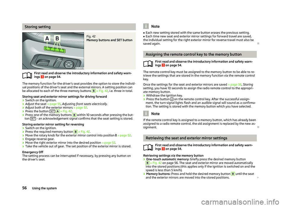
Fig. 42
Memory buttons and SET button
First read and observe the introductory information and safety warn-
ings on page 54.
The memory function for the driver's seat provides the option to store the individ-
ual positions of the driver's seat and the external mirrors. A setting position can
be allocated to each of the three memory buttons B
» Fig. 42, i.e. three in total.
Storing seat and exterior mirror settings for driving forward
› Switch on the ignition.
› Adjust the seat
» page 55, Adjusting front seats electrically .
› Adjust both of the exterior mirrors
» page 52.
› Press the button
SET A
» Fig. 42.
› Press one of the memory buttons B
within 10 seconds after pressing the but-
ton SET - an acknowledgement signal confirms that the seat setting is stored.
Storing exterior mirror setting for reversing › Switch on the ignition.
› Press the required memory button B
» Fig. 42.
› Move the rotary knob for the exterior mirror control into position
» page 52.
› Engage reverse gear.
› Move the right exterior mirror into the desired position
» page 52.
› Take the vehicle out of gear. The set position of the exterior mirror is stored.
Emergency Off
The setting process can be interrupted if necessary, by pressing any button on
the driver's seat.
ä Note
■ Each new setting stored with the same button erases the previous setting.
■ Each time new seat and exterior mirror settings for forward travel are saved,
the individual setting for the right exterior mirror for reverse travel must also be
saved again. Ð Assigning the remote control key to the memory button
First read and observe the introductory information and safety warn-
ings on page 54.
The remote control key must be assigned to the memory button to be able to re-
trieve the settings that are stored in the memory function via the remote control
key.
Once the settings for the seat and exterior mirrors are saved » page 56, Storing
setting, you have 10
seconds to assign the radio remote control to the appropri-
ate memory button.
› Withdraw the ignition key.
› Press the button
on the remote control key. After the successful assign-
ment, the turn signal lights flash and an audible signal will sound as a confirma-
tion. The setting is stored with the memory button which you have selected. Note
If the remote control key is assigned to a memory button, which has already been
assigned to a radio remote control, the old assignment is replaced by the new as-
signment. Ð Retrieving the seat and exterior mirror settings
First read and observe the introductory information and safety warn-
ings on page 54.
Retrieving settings via the memory button
›
One-touch automatic memory:
briefly press the desired memory button B
» Fig. 42 on page 56. The seat and exterior mirror are moved automatically
into the stored positions (this applies only if the ignition is switched on and the
speed is less than 5 km/h).
› Memory buttons:
Press and hold the desired memory button B
until the seat
and the exterior mirrors are moved into the stored positions. £
ä
ä
56 Using the system
Page 59 of 218
Retrieving settings via the remote control key
›
If the driver's door is closed and the ignition is switched off, briefly press the
button on the remote control key and open the driver's door.
The seat and exterior mirrors now move automatically into the stored positions.
Retrieving setting of exterior mirror for reversing
› Turn the rotary knob for the exterior mirror setting into the position
» page 52
before engaging the reverse gear.
› Engage reverse gear.
The mirror returns into its initial position, after the rotary knob is moved out of
the position and put into another position or if the speed is more than 15 km/h.
Emergency Off
The setting process for the seats and exterior mirrors can be interrupted if neces-
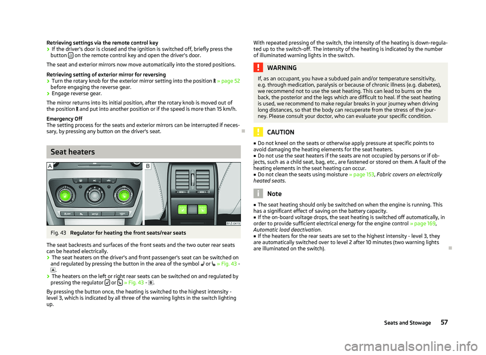
sary, by pressing any button on the driver's seat. ÐSeat heaters
Fig. 43
Regulator for heating the front seats/rear seats
The seat backrests and surfaces of the front seats and the two outer rear seats
can be heated electrically. › The seat heaters on the driver's and front passenger's seat can be switched on
and regulated by pressing the button in the area of the symbol or
»
Fig. 43 -
.
› The heaters on the left or right rear seats can be switched on and regulated by
pressing the regulator or
» Fig. 43 -
.
By pressing the button once, the heating is switched to the highest intensity -
level 3, which is indicated by all three of the warning lights in the switch lighting
up. With repeated pressing of the switch, the intensity of the heating is down-regula-
ted up to the switch-off. The intensity of the heating is indicated by the number
of illuminated warning lights in the switch. WARNING
If, as an occupant, you have a subdued pain and/or temperature sensitivity,
e.g. through medication, paralysis or because of chronic illness (e.g. diabetes),
we recommend not to use the seat heating. This can lead to burns on the
back, the posterior and the legs which are difficult to heal. If the seat heating
is used, we recommend to make regular breaks in your journey when driving
long distances, so that the body can recuperate from the stress of the jour-
ney. Please consult your doctor, who can evaluate your specific condition. CAUTION
■ Do not kneel on the seats or otherwise apply pressure at specific points to
avoid damaging the heating elements for the seat heaters.
■ Do not use the seat heaters if the seats are not occupied by persons or if ob-
jects, such as a child seat, bag, etc., are fastened or stored on them. A fault of the
heating elements in the seat heating can occur.
■ Do not clean the seats using moisture » page 153, Fabric covers on electrically
heated seats. Note
■ The seat heating should only be switched on when the engine is running. This
has a significant effect of saving on the battery capacity. ■ If the on-board voltage drops, the seat heating is switched off automatically, in
order to provide sufficient electrical energy for the engine control » page 169,
Automatic load deactivation .
■ If the heaters for the rear seats are set to the highest intensity - level 3, they
are automatically switched over to level
2 after 10 minutes (two warning lights
are illuminated on the switch). Ð
57
Seats and Stowage
Page 60 of 218
Head restraints
ä
Introduction
This chapter contains information on the following subjects:
Adjusting, removing and installing a head restraint 58
Middle rear head restraint 58
Best protection is achieved if the top edge of the head restraint is at the same
level as the upper part of your head.
The position of the front and rear outer head restraints is adjustable in height.
The middle rear head restraint is adjustable in two positions.
The head restraints must be adjusted to match the size of the seat occupant. Cor-
rectly adjusted head restraints together with the seat belts offer effective protec-
tion for the occupants » page 122, Correct seated position .WARNING
■ The head restraints must be correctly adjusted in order to offer effective
protection for the occupants in the event of an accident. ■ Never drive with the head restraints removed - risk of injury.
■ If the rear seats are occupied, the rear head restraint must not be in the
lower position. ÐAdjusting, removing and installing a head restraint
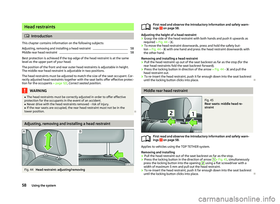
Fig. 44
Head restraint: adjusting/removing First read and observe the introductory information and safety warn-
ings on page 58.
Adjusting the height of a head restraint
› Grasp the side of the head restraint with both hands and push it upwards as
required » Fig. 44 - .
› To move the head restraint downwards, press and hold the safety but-
ton » Fig. 44 - with one hand and press the head restraint downwards with
the other hand.
Removing and installing a head restraint
› Pull the head restraint up out of the seat backrest as far as the stop (for the
rear head restraints fold the seat backrest forward).
› Press the locking button in direction of the arrow
» Fig. 44 - and pull the
head restraint out.
› To re-insert the head restraint, push it far enough down into the seat backrest
until the locking button clicks into place. Ð Middle rear head restraint
Fig. 45
Rear seats: middle head re-
straint
First read and observe the introductory information and safety warn-
ings on page 58.
Applies to vehicles using the TOP TETHER system.
Removing and installing
› Pull the head restraint out of the seat backrest as far as the stop.
› Press the locking button in the direction of arrow 1
» Fig. 45
, simultaneously
press the locking button into the opening 2
using a flat screwdriver with a
width of maximum 5 mm and pull out the head restraint.
› To re-insert the head restraint, push it far enough down into the seat backrest
until the locking button clicks into place. Ð
ä
ä
58 Using the system