technical data SKODA OCTAVIA 2007 1.G / (1U) Workshop Manual
[x] Cancel search | Manufacturer: SKODA, Model Year: 2007, Model line: OCTAVIA, Model: SKODA OCTAVIA 2007 1.G / (1U)Pages: 288, PDF Size: 15.19 MB
Page 108 of 288
Heating and air conditioning system107
Using the systemSafetyDriving TipsGeneral MaintenanceBreakdown assistanceTechnical Data
Air outlet vents
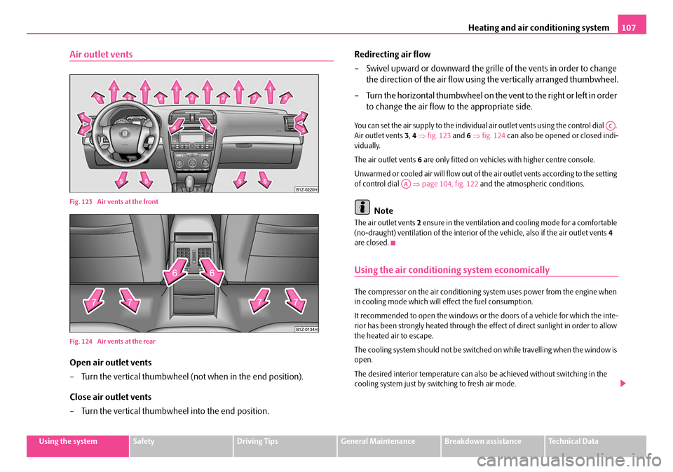
Fig. 123 Air vents at the front
Fig. 124 Air vents at the rear
Open air outlet vents
– Turn the vertical thumbwheel (not when in the end position).
Close air outlet vents
– Turn the vertical thumbwheel into the end position. Redirecting air flow
– Swivel upward or downward the grille of the vents in order to change
the direction of the air flow using the vertically arranged thumbwheel.
– Turn the horizontal thumbwheel on the vent to the right or left in order to change the air flow to the appropriate side.
You can set the air supply to the individual air outlet vents using the control dial .
Air outlet vents 3, 4 ⇒ fig. 123 and 6 ⇒ fig. 124 can also be opened or closed indi-
vidually.
The air outlet vents 6 are only fitted on vehicles with higher centre console.
Unwarmed or cooled air will flow out of the air outlet vents according to the setting
of control dial ⇒page 104, fig. 122 and the atmosphe ric conditions.
Note
The air outlet vents 2 ensure in the ventilation and cooling mode for a comfortable
(no-draught) ventilation of the interior of the vehicle, also if the air outlet vents 4
are closed.
Using the air conditioning system economically
The compressor on the air conditioning sy stem uses power from the engine when
in cooling mode which will effect the fuel consumption.
It recommended to open the windows or the doors of a vehicle for which the inte-
rior has been strongly heated through the effect of di rect sunlight in order to allow
the heated air to escape.
The cooling system should not be switched on while travelling when the window is
open.
The desired interior temperature can also be achieved without switching in the
cooling system just by sw itching to fresh air mode.
AC
AA
NKO A5 20 MR08.book Page 107 Wednesday, April 11, 2007 2:54 PM
Page 110 of 288
Heating and air conditioning system109
Using the systemSafetyDriving TipsGeneral MaintenanceBreakdown assistanceTechnical Data
•You should not leave recirculated air mode on over a longer period of
time, as “stale” air may result in fatigue in the driver and occupants, divert
your attention and also cause the windows to mist up. The risk of having an
accident increases. Switch recirculated air mode off as soon as the windows
begin misting up.
Note
•If the cooling system has not been switched on for a lengthy period, odours may
be produced at the evaporator because of deposits. Switch the cooling system on
at least once a month for approximately 5 minutes at the highest blower stage - also
during the cold season of the year - in order to remove such odours. Also open a
window for a short time.
•We recommend that you do not smoke in the vehicle when the recirculating air
mode is operating since the smoke which is drawn at the evaporator from the inte-
rior of the vehicle forms deposits in the evaporator of the air conditioning system.
This produces a permanent odour when the air conditioning system is operating
which can only be eliminated through co nsiderable effort and expense (replace-
ment of compressor).
•The used air streams out through the air removal openings in the luggage
compartment.
•The Information of the Climatronic is displayed on the display of the radio*. You
can also switch off this function - see operating instructions for radio
•Using the cooling economically ⇒page 107.
•Operational problems ⇒page 108.
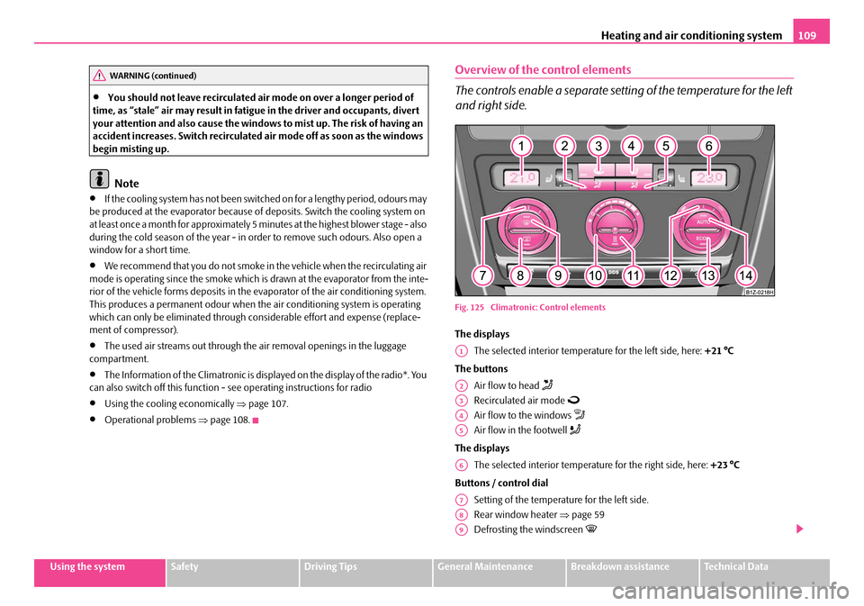
Overview of the control elements
The controls enable a separate sett ing of the temperature for the left
and right side.
Fig. 125 Climatroni c: Control elements
The displays
The selected interior temperature for the left side, here: +21 °C
The buttons Air flow to head
Recirculated air mode
Air flow to the windows
Air flow in the footwell
The displaysThe selected interior temperature for the right side, here: +23 °C
Buttons / control dial Setting of the temperature for the left side.
Rear window heater ⇒page 59
Defrosting the windscreen
WARNING (continued)
A1
A2
A3
A4
A5
A6
A7
A8
A9
NKO A5 20 MR08.book Page 109 Wednesday, April 11, 2007 2:54 PM
Page 112 of 288
Heating and air conditioning system111
Using the systemSafetyDriving TipsGeneral MaintenanceBreakdown assistanceTechnical Data
Defrosting windscreen - switching off
– Once again press the button or the button .
The temperature control is controlled automatically. More air flows out of the air
outlet vents 1 and 2.
Recirculated air mode
In recirculated air mode air is sucked out of the interior of the vehicle
and then fed back into the interior.
Recirculated air mode prevents polluted air outside the vehicle from
getting into the vehicle, for example when driving through a tunnel or
when standing in a traffic jam.
Switching recirculated air mode on
– Press the button - the warning light lights up in the button.
Switching recirculated air mode off
– Press again the button or the button - the warning light in
the button goes out.
WARNING
You should not leave recirculated air mode on over a longer period of time,
as “stale” air may result in fatigue in the driver and occupants, divert your
attention and also cause the windows to mist up. The risk of having an acci-
dent increases. Switch recirculated air mode off as soon as the windows
begin misting up.
Note
If the windscreen mists up, press the button ⇒page 109, fig. 125 . After the
windscreen has been demisted, press the button .
Setting temperature
You can separate the interior temperature for the left and right side sepa-
rately.
– You can set the temperature for both sides after switching on the igni- tion with the control dial .
– If you wish to set the temperature for the right side, turn the control dial .
If the temperature for the right side was set via the control dial , it can no longer
be set via the control dial - temperature fo r both sides. This is only possible if
you press the button for about 2 seconds.
You can set the interior temperature between +16 °C (60 °F) and +29,5 °C (85 °F).
The interior temperature is regulated automatically within this range. If you select
the temperature below +16 °C (60 °F), “LO” appears in the display. If you select the
temperature higher than +29,5 °C (85 °F), “HI” appears in the display. In both limit
positions the Climatronic operates at maximum cooling or heating capacity,
respectively. The temperature is not controlled in this case.
Lengthy and uneven distribution of the air flow out of the vents (in particular at the
leg area) and large differences in temperat ure, for example when getting out of the
vehicle, can result in chills in sensitive persons.
Controlling blower
There are a total of seven blower stages available.
The Climatronic system controls the bl ower stages automatically in line
with the interior temperature. You can also, however, adapt the blower
stages manually to suit your particular needs.
– Turn the control dial ⇒page 109, fig. 125 to the left (reduce
blower speed) or right (increase blower speed).
Switch off the blowers, the Climatronic is switched off and in the display shows OFF.
AUTO
AUTO
A9AUTO
A7
A11
A11A7AUTO
A10
NKO A5 20 MR08.book Page 111 Wednesday, April 11, 2007 2:54 PM
Page 114 of 288
Heating and air conditioning system113
Using the systemSafetyDriving TipsGeneral MaintenanceBreakdown assistanceTechnical Data
Note
The air outlet vents 2 ensure in the ventilation and cooling mode for a comfortable
(no-draught) ventilation of th e interior of the vehicle, also if the air outlet vents 4
are closed.
Auxiliary heating system (auxiliary heating and
ventilation)*
Description
The auxiliary heating (auxiliary heating and ventilation) heats or
supplies the interior of the vehicl e with fresh air independent of the
engine.
Auxiliary heating (auxiliary heating)
The auxiliary heating (auxiliary heating) f unctions in connection with the heater or
with the Climatic or Climatronic.
It can be used when stationa ry, when engine is switched off for preheating of the
vehicle as well as while driving (e.g. during the heating phase of the engine).
The auxiliary heating (auxiliary heating) warms up the coolant during the combus-
tion of fuel from the vehicle tank. The cool ant warms up the air, which (if the blower
speed is not set to zero) flows into the occupant compartment.
6)
Auxiliary ventilation
The auxiliary ventilation enables fresh air to flow into the vehicle interior by
switching on the blower, if the blower speed is not set to zero, whereby the interior
temperature is effectively decreased (e.g. with a vehicle parked in the sun).
Using the system
So that the auxiliary heating (auxiliary heating and ventilation) func-
tions according to your expectations, it is necessary to carry out the
basic setting before its programming.
Basic setting
– In the information display, select from the menu Main menu the
Menu Setup (settings) ⇒ page 19, fig. 11 .
– In the menu Settings select the menu Aux. Heating (auxiliary
heating).
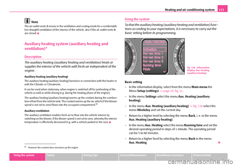
– In the menu Aux. Heating (auxiliary heating) ⇒ fig. 128 select the
menu Weekday and set the current day.
– Return to a higher level by selecting the menu Back, i. e. in the menu
Aux. Heating (auxiliary heating) .
– In the menu Aux. Heating select the menu Running time and set the
desired operating period in steps of 1 minute. The operating period
can be 5 to 60 minutes.
– Return to a higher level by selecting the menu Back in the menu
Aux. Heating .
6)However the coolant does not warm up the engine.
Fig. 128 Information
display: Aux. Heating
(auxiliary heating)
NKO A5 20 MR08.book Page 113 Wednesday, April 11, 2007 2:54 PM
Page 116 of 288
Heating and air conditioning system115
Using the systemSafetyDriving TipsGeneral MaintenanceBreakdown assistanceTechnical Data
WARNING
•The auxiliary heating must never be operated in closed rooms - risk of
poisoning!
•The auxiliary heating must not be running during refueling - risk of fire.
•The exhaust pipe of the auxiliary heating is located on the underside of
the vehicle. Therefore do not place the vehicle, if you wish to operate the
auxiliary heating, in such a way that the exhaust gases of the auxiliary
heating can come easily into contact with inflammable materials (e.g. dry
grass) or easily inflammable su bstances (e.g. fuel run out).
Note
•If the auxiliary heating runs, the fuel consumption comes from the vehicle tank.
Therefore the auxiliary heating should not be operated, if there is very little fuel in
the tank.
•The exhaust pipe of the auxiliary heating, which is located on the underside of
the vehicle, must not be clogged and the exhaust flow must not be blocked.
•If the auxiliary heat ing and ventilation is running, the vehicle battery discharges.
If the auxiliary heating and ventilation has been operated several times over a
longer period, the vehicle must be driven a few kilometers in order to recharge the
vehicle battery.
•The auxiliary heating only sw itches the blower on, if it has achieved a coolant
temperature of approx. 50 °C.
•At low outside temperatures, this can resu lt in a formation of water vapour in
the area of the engine compartment. This is quite normal and is not an operating
problem.
•After switching off the auxiliary heating, the coolant pump runs for a short
period.
•The auxiliary heating and ventilation does not switch on or comes on, if the
vehicle battery indicate s a low loading state.
•The auxiliary heating (auxiliary heating) switches on, if in the information
display: Please refuel! is indicated or was indicated before switching off the igni-
tion.
•When driving, the auxiliary heating can only be switched on, if the exterior
temperature is lower than 5 °C.
•The air inlet in front of the windscreen mu st be free of ice, snow or leaves in
order to ensure that the auxiliary heating operates properly.
•So that the warm air can flow into the vehicle interior after switching on the
auxiliary heating (auxiliary heating), the control dial ⇒page 100, fig. 119 must
be turned up to the stop to the right when heating. With Climatic and Climatronic,
you can maintain the temperature norma lly selected by you (we recommend 22
°C). It is recommended to put the air flow in the position
. For heating and
climatic put the blower switch ⇒page 100, fig. 119 if necessary ⇒page 104,
fig. 122 in the position 2.
•On vehicles with DPF (die sel particle filter) the warm coolant heats up the
engine.
AA
AB
NKO A5 20 MR08.book Page 115 Wednesday, April 11, 2007 2:54 PM
Page 118 of 288
Starting-off and Driving117
Using the systemSafetyDriving TipsGeneral MaintenanceBreakdown assistanceTechnical Data
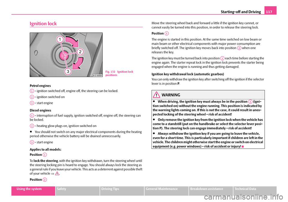
Ignition lock
Petrol engines
- ignition switched off, engine off, the steering can be locked.
- ignition switched on
- start engine
Diesel engines - interruption of fuel supply, ignition switched off, engine off, the steering can
be locked.
- heating glow plugs on, ignition switched on
•You should not switch on any major elec trical components during the heating
period otherwise the vehicle batter y will be drained unnecessarily.
- start engine
Applies to all models:
Position
To lock the steering , with the ignition key withdrawn, turn the steering wheel until
the steering locking pin is heard to engage. You should always lock the steering as
a general rule if you leave your vehicle. This acts as a deterrent against possible theft
of your vehicle ⇒.
Position Move the steering wheel back and forward
a little if the ignition key cannot, or
cannot easily be turned into this position, in order to release the steering lock.
Position
The engine is started in this position. At the same time switched on low beam or
main beam or other electrical compon ents with major power consumption are
briefly switched off. The ignition key moves back into position when one
releases the key.
The ignition key must be turned back into position each time before starting the
engine again. The starter repeat lock in th e ignition lock prevents the starter being
engaged when the engine is ru nning and thus getting damaged.
Ignition key withdrawal lock (automatic gearbox)
You can only withdraw the ignition key after switching off the ignition if the selector
lever is in position P.
WARNING
•When driving, the ignition key must always be in the position (igni-
tion switched on) without the engine running. This position is indicated by
the warning lights coming on. If this is not the case, it could result in unex-
pected locking of the steering wheel - risk of accident!
•Only remove the ignition key from the ignition lock when the vehicle has
come to a standstill (put on the handbrake or select the selector lever posi-
tion P). The steering lock can enga ge immediately - risk of accident!
•Always withdraw the ignition key if you are going to leave the vehicle,
even for a short time. This is particularly important if children are left in the
vehicle. The children might otherwise star t the engine or switch on electrical
equipment (e.g. power windows) - risk of accident or injury!
Fig. 132 Ignition lock
positions
A1
A2
A3
A1
A2
A3
A1
A2
A3
A2
A1
A2
NKO A5 20 MR08.book Page 117 Wednesday, April 11, 2007 2:54 PM
Page 120 of 288
Starting-off and Driving119
Using the systemSafetyDriving TipsGeneral MaintenanceBreakdown assistanceTechnical Data
You should not switch on any major electrical components during the heating
period otherwise the vehicle battery will be drained unnecessarily.
•You should start the engine immediately after the glow plug warning light
has gone out.
•The glow plug warning light will come on for about one second if the engine is
at a normal operating temperature or if th e outside temperature is above +5°C. This
means that you can start the engine right away.
•Interrupt the attempt at starting after 10 seconds if the engine does not start
right awayand wait for about 30 seconds before repeating the attempt.
•It is possible that the fuse on the diesel preglow system is defect if the engine
still does not start. Check the fuse and replace it if necessary ⇒page 243.
•Contact the nearest specialist garage to obtain professional assistance.
Starting the engine after the fuel tank has run dry
It may take longer than normal to start the engine after refuelling if the fuel tank has
run completely dry - up to one minute. This is because the fuel system must first of
all be filled while the attempting to start the engine.
Switching off the engine
– The engine can be switched off by turning the ignition key from posi- tion ⇒page 117, fig. 132 into position .
WARNING
•Never switch off the engine before the vehicle is stationary - risk of acci-
dent!
•The brake booster only operates when the engine is running. Greater
physical effort for braking is required when engine is switched off. Because
if you do not stop as normal, this can cause an accident and severe injuries.
Caution
you should not switch the engine off right away at the end of your journey after the
engine has been operated for a lengthy peri od at high loads but should be allowed
it to run at idling speed for about 2 minutes. This prevents any accumulation of heat
when the engine is switched off.
Note
•The radiator fan may continue running fo r a further 10 minutes or so after the
engine and the ignition have been switched off. The coolant fan may, however, also
switch on again after some time if the coolant temperature rises because of an
accumulation of heat in the engine or if the engine is warm and the engine
compartment is additionally heated by strong sunlight.
•This is why particular care is required when carrying out any work in the engine
compartment ⇒page 210, “Working in the engine compartment”.
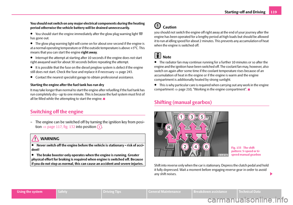
Shifting (manual gearbox)
Shift into reverse only when the car is stationary. Depress the clutch pedal and hold
it fully depressed. Wait a moment before engaging reverse gear in order to avoid
any shift noises.
A1
Fig. 133 The shift
pattern: 5-speed or 6-
speed manual gearbox
NKO A5 20 MR08.book Page 119 Wednesday, April 11, 2007 2:54 PM
Page 122 of 288
Starting-off and Driving121
Using the systemSafetyDriving TipsGeneral MaintenanceBreakdown assistanceTechnical Data
Rear parking aid*
The parking aid provides a warning of obstacles behind the vehicle.
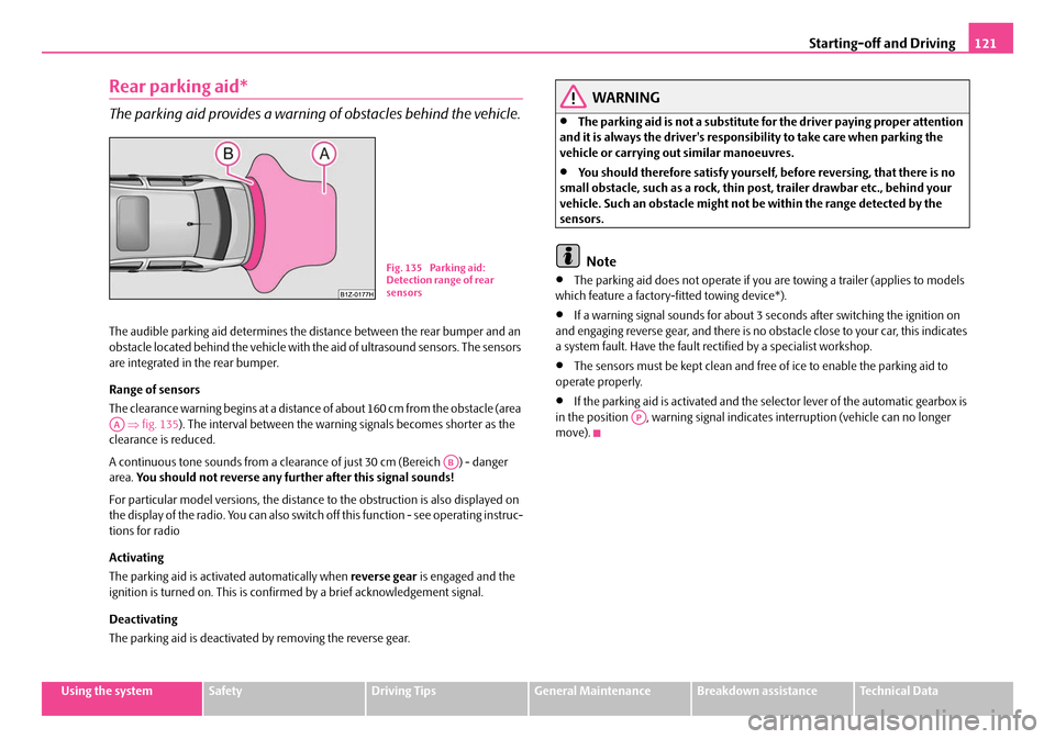
The audible parking aid determines the distance between the rear bumper and an
obstacle located behind the vehicle with the aid of ultrasound sensors. The sensors
are integrated in the rear bumper.
Range of sensors
The clearance warning begins at a distance of about 160 cm from the obstacle (area
⇒ fig. 135 ). The interval between the warning signals becomes shorter as the
clearance is reduced.
A continuous tone sounds from a clearanc e of just 30 cm (Bereich ) - danger
area. You should not reverse any further after this signal sounds!
For particular model versions, the distance to the obstruction is also displayed on
the display of the radio. You can also switch off this function - see operating instruc-
tions for radio
Activating
The parking aid is activated automatically when reverse gear is engaged and the
ignition is turned on. This is confirmed by a brief acknowledgement signal.
Deactivating
The parking aid is deactivated by removing the reverse gear.
WARNING
•The parking aid is not a substitute for the driver paying proper attention
and it is always the driver's responsibility to take care when parking the
vehicle or carrying ou t similar manoeuvres.
•You should therefore satisfy yourself, before reversing, that there is no
small obstacle, such as a rock, thin po st, trailer drawbar etc., behind your
vehicle. Such an obstacle might not be within the range detected by the
sensors.
Note
•The parking aid does not operate if you are towing a trailer (applies to models
which feature a factory-fi tted towing device*).
•If a warning signal sounds for about 3 seconds after switching the ignition on
and engaging reverse gear, and there is no obstacle close to your car, this indicates
a system fault. Have the fault rectified by a specialist workshop.
•The sensors must be kept clean and free of ice to enable the parking aid to
operate properly.
•If the parking aid is activated and the selector lever of the automatic gearbox is
in the position , warning signal indicates interruption (vehicle can no longer
move).
Fig. 135 Parking aid:
Detection range of rear
sensors
AA
AB
AP
NKO A5 20 MR08.book Page 121 Wednesday, April 11, 2007 2:54 PM
Page 124 of 288
Starting-off and Driving123
Using the systemSafetyDriving TipsGeneral MaintenanceBreakdown assistanceTechnical Data
Note
•Only the front parking aid operates if you are towing a trailer (applies only to
models which feature a factory-fitted towing device*).
•If a warning signal sounds for about 3 seconds after activating the system and
there is no obstacle close to your car, th is indicates a system fault. The fault is
confirmed additionally when the symbol
flashes in the button ⇒page 122,
fig. 136 . Have the fault rectified by a specialist workshop.
•The sensors must be kept clean and free of ice to enable the parking aid to
operate properly.
•If the parking aid is activated and the se lector lever of the automatic gearbox is
in the position , warning signal indicates interruption (vehicle can no longer
move).
Cruise control system (CCS)*
Introduction
The cruise control system (CCS) maintains a constant speed, more than 30 km/h (20
mph), once it has been set, without you having to depress the accelerator pedal.
This is only possible within the range wh ich is permitted by the power output and
braking power of the engine. The cruise co ntrol system makes it possible - particu-
larly on long journeys - for you to rest your “accelerator foot”.
WARNING
•The cruise control system must not, for safety reasons, be used in dense
traffic or on unfavourable road surfaces (such as icy roads, slippery roads or
loose chippings) - risk of accident!
•In order to prevent unintentional use of the cruise control system, always
switch off the system after use.
Note
•Models fitted with a manual gearbox: Al ways depress the clutch pedal if you
switch on the cruise control system when the gearbox is in Neutral. Otherwise the
engine can rev up unintentionally.
•The cruise control system is not able to maintain a constant speed when driving
on steep downhill sections. The weight of the vehicle increases the speed at which
it travels. One should shift down in good time to a lower gear or slow the vehicle
down by applying the foot brake.
•It is not possible on vehicles fitted with an automatic gearbox to switch on the
cruise control system if the sele ctor lever is in the position P, N or R.
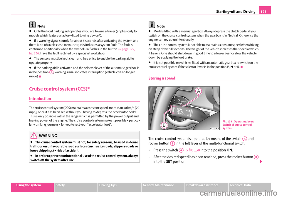
Storing a speed
The cruise control system is operated by means of the switch and
rocker button in the left lever of the multi-functional switch.
– Press the switch ⇒fig. 138 into the position ON.
– After the desired speed has been reached, press the rocker button into the SET position.
AP
Fig. 138 Operating lever:
Switch of cruise control
system
AA
AB
AA
AB
NKO A5 20 MR08.book Page 123 Wednesday, April 11, 2007 2:54 PM
Page 126 of 288

Starting-off and Driving125
Using the systemSafetyDriving TipsGeneral MaintenanceBreakdown assistanceTechnical Data
Switching off the cruise control system completely
– Press the switch ⇒page 123, fig. 138 to the right into position
OFF .AA
NKO A5 20 MR08.book Page 125 Wednesday, April 11, 2007 2:54 PM