Lock SKODA OCTAVIA 2008 2.G / (1Z) Repair Manual
[x] Cancel search | Manufacturer: SKODA, Model Year: 2008, Model line: OCTAVIA, Model: SKODA OCTAVIA 2008 2.G / (1Z)Pages: 304, PDF Size: 17.69 MB
Page 137 of 304
Automatic gearbox
136
result of this the vehicle can no longer be driven. If the clutch opens automatically,
depress the brake pedal, wait a few se conds and only then continue driving.
Selector lever positions
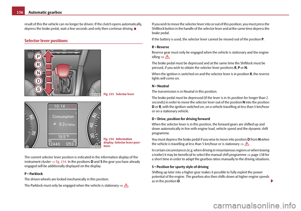
The current selector lever position is in dicated in the information display of the
instrument cluster ⇒fig. 154 . In the positions D and S the gear you have already
engaged will be additionally displayed on the display.
P - Parklock
The driven wheels are locked mechanically in this position.
The Parklock must only be engaged when the vehicle is stationary ⇒. I f y o u w i s h t o m o v e t h e s e l e c t o r l e v e r i n to
or out of this position, you must press the
Shiftlock button in the handle of the selector lever and at the same time depress the
brake pedal.
If the battery is used, the selector leve r cannot be moved out of the position P .
R - Reverse
Reverse gear must only be engaged when the vehicle is stationary and the engine
idling ⇒ .
The brake pedal must be depressed and at the same time the Shiftlock must be
pressed, if you wish to obtain the selector lever positions R, P or N.
When the ignition is switched on and the selector lever is in position R, the reverse
lights will come on.
N - Neutral
The transmission is in Neutral in this position.
The brake pedal must be depressed (if the lever is in its position for longer than 2
seconds) in order to move the selector lever out of the position N into the position
D or R , with the ignition switched on, on a vehicle travelling at less than 5 km/hour
or on a stationary vehicle.
D - Drive, position for driving forward
When the selector lever is in this position, the forward gears are shifted up and
down automatically in line with engine load, vehicle speed and the dynamic shift
programme.
You must depress the brake pedal if you wise to move into position D from N when
the vehicle is travelling at less than 5 km/hour or is stationary ⇒.
In certain circumstances (e.g. when driving in mountainous regions or when towing
a trailer) it may be beneficial to select the manual shift programme ⇒page 138 for
a short time in order to adapt the gearbox ratios manually to the driving situations.
S - Position for sporty style of driving
Shifting up later into a higher gear makes it possible to fully exploit the power
potential of the engine. The gearbox also then shifts down at higher engine speeds
as in the position D.
Fig. 153 Selector lever
Fig. 154 Information
display: Selector lever posi-
tions
20A5Facelift.book Page 136 Saturday, September 6, 2008 2:13 PM
Page 138 of 304
Automatic gearbox137
Using the systemSafetyDriving TipsGeneral MaintenanceBreakdown assistanceTechnical Data
The gearbox does not shift into the 6th gear in the position
S, because the
maximum speed is reached with the 5th gear
12).
The Shiftlock on the selector lever grip must be pressed when moving the selector
lever out of the position D into the position S.
WARNING
•Never move the selector lever into position R or P when driving - risk of
an accident!
•When the engine is running and the vehicle is stationary, it is necessary
to hold the car with the brake pedal in all the positions of the selector lever
(except P and N) since the power transmission is never completely inter-
rupted, also not when the engine is idling - the vehicle "creeps".
•You must on no account unintentionally operate the throttle (e.g. by
hand from the engine compartment) if a drive position is engaged when the
car is stationary. The vehicle would ot herwise immediately start off - also
when the handbrake is firmly applied - risk of an accident!
•You must move the selector lever into position P and firmly apply the
handbrake first before you or any other person opens the bonnet and starts
working on the engine when it is running - risk of accident! It is also essential
to observe all warnings ⇒page 225, “Working in the engine
compartment”.
Selector lever lock
Automatic selector lever lock
With the ignition on, the selector lever is locked when it is in the positions P and N.
You must first of all depress the brake peda l in order to move the selector lever out
of this position. The warning light
⇒ page 38 lights up in the instrument cluster
as a reminder for the driver when the selector lever is in position P and N:
A time delay element ensures that the selector lever is not blocked when rapidly
switching over the position N (e.g. from R to D). This does, for example, allow one to seesaw out a stuck vehicle. The selector
lever lock will click into place if the lever
is in the N position for more than 2 seconds without the brake pedal being pressed.
The selector lever lock is only active if th e vehicle is stationary or moving at speed
of less than 5 km/hour. The lock is switched off automatically into position N when
the car is travelling at a higher speed.
Shiftlock button
The Shiftlock button in the handle of selector lever prevents certain selector lever
positions being engaged inadvertently. The selector lever lock is cancelled when
you press the Shiftlock button.
Keylock - Ignition key withdrawal lock
You can only withdraw the ignition key after switching off the ignition if the selector
lever is in position P. If the ignition key is withdrawn, the selector lever is blocked in
position P.
Kickdown function
The kickdown function provides you with maximum acceleration
power.
Depressing the accelerator pedal allows the kickdown function to be activated in
the desired driving program. This function has precedence over the driving
programme and serves for maximum accelera tion of the vehicle when exploiting
the maximum power potential of the engine without taking into account the
current selector lever position ( D, S or Tiptronic ). The gearbox shifts down to one
or several gears in line with the driving state and the vehicle accelerates. The
gearbox does not shift up into the highes t gear until the engine has reached its
maximum revolutions for this gear range.
WARNING
Please note that using the kickdown f unction can result in the driven wheels
spinning on a smooth or slippery road surface - risk of skidding!
12)Not valid for vehicles with automatic gearbox DSG.
20A5Facelift.book Page 137 Saturday, September 6, 2008 2:13 PM
Page 141 of 304
Automatic gearbox
140
Selector lever-emergency unlocking
In case of interruption of the power su pply (e.g. flat vehicle battery, defec-
tive fuse) or defect of the selector lever lock, the selector lever can no
longer be shifted from the position P in the normal way and the vehicle
can no longer be moved. The selector lever must be unlocked in case of
emergency.
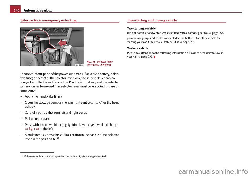
– Apply the handbrake firmly.
– Open the stowage compartment in front centre console* or the front ashtray.
– Carefully pull up the front left and right cover.
– Pull up rear cover.
– Press with a narrow object (e.g. ignition key) the yellow plastic hoop ⇒fig. 158 to the left.
– Simultaneously press the shiftlock button in the handle of the selector lever in the position N
13).
Tow-starting and towing vehicle
Tow-starting a vehicle
It is not possible to tow-start vehi cles fitted with automatic gearbox ⇒ page 253.
you can use jump-start cables connected to the battery of another vehicle for
starting your car if the vehicle battery is flat ⇒page 252.
Towing a vehicle
Please pay attention to the following info rmation if it comes necessary to tow-in
your car ⇒page 253.
13)If the selector lever is moved again into the position P, it is once again blocked.
Fig. 158 Selector lever-
emergency unlocking
20A5Facelift.book Page 140 Saturday, September 6, 2008 2:13 PM
Page 146 of 304
Communication145
Using the systemSafetyDriving TipsGeneral MaintenanceBreakdown assistanceTechnical Data
•Please operate your mobile phone exclus ively with a suitable adapter in order
to keep a low radiation in the vehicle.
•Inserting the mobile phone into the adapter ensures an optimal sending and
receiving power and offers at the same ti me the advantage of the battery charging.
•Note that the range of the Bluetooth® connection to the handsfree-system is
limited to the vehicle interior. The range is dependent on local factors, e.g. obstacles
between the devices and interferences with other devices. If your mobile phone is
e.g. in a jacket pocket, this can lead to difficulties when establishing the Bluetooth
®
connection with the handsfree-system or the data transfer.
Inserting the mobile phone with the adapter*
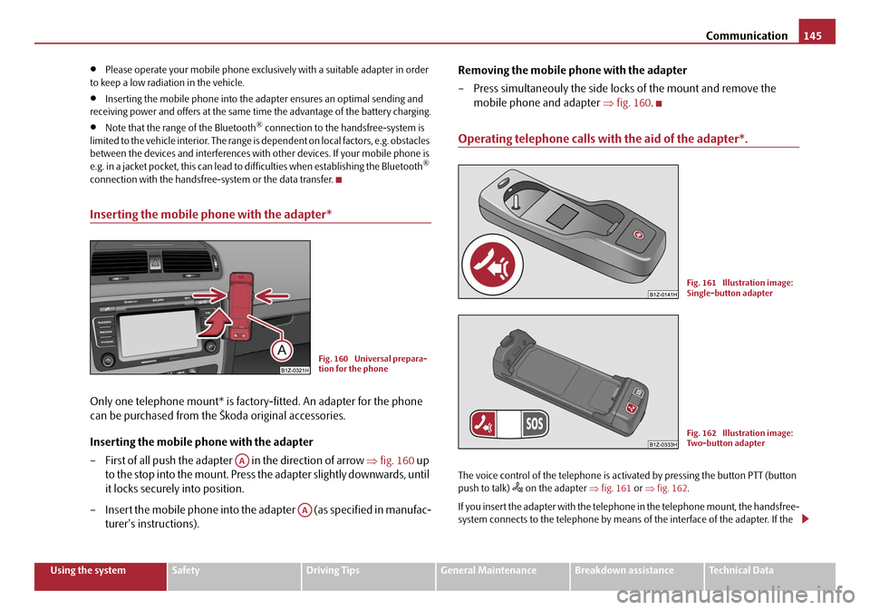
Only one telephone mount* is factory-fitted. An adapter for the phone
can be purchased from the Škoda original accessories.
Inserting the mobile phone with the adapter
– First of all push the adapter in the direction of arrow ⇒fig. 160 up
to the stop into the mo unt. Press the adapter slightly downwards, until
it locks securely into position.
– Insert the mobile phone into the adapter (as specified in manufac- turer's instructions). Removing the mobile phone with the adapter
– Press simultaneouly the side locks of the mount and remove the
mobile phone and adapter ⇒fig. 160 .
Operating telephone calls with the aid of the adapter*.
The voice control of the telephone is acti vated by pressing the button PTT (button
push to talk) on the adapter ⇒fig. 161 or ⇒fig. 162 .
If you insert the adapter with the telephone in the telephone mount, the handsfree-
system connects to the telephone by means of the interface of the adapter. If the
Fig. 160 Universal prepara-
tion for the phone
AA
AA
Fig. 161 Illustration image:
Single-button adapter
Fig. 162 Illustration image:
Two-button adapter
20A5Facelift.book Page 145 Saturday, September 6, 2008 2:13 PM
Page 150 of 304
Communication149
Using the systemSafetyDriving TipsGeneral MaintenanceBreakdown assistanceTechnical Data
•the mobile phone are switched on.
The digits zero to nine are permitted. The system detects no continuous digit
combinations such as twenty-three, but only individually spoken digits (two, three).
After each order of digits (separation through brief voice pause) the detected digits
are repeated.
Notes for entering the PIN code
•When entering a PIN code with more than 8 digits, the system indicates “The
PIN is too long ”.
•When entering an incorrect PIN code, the system indicates “ The PIN is incor-
rect ”.
•If the incorrect PIN code has been ente red three times consecutively, the card
is blocked. With the aid of the person al unblocking code PUK (Personal Unblock
Key), the SIM card can be unblocked. The unblocking code can only be entered
via the phone keypad and not through the voice control.
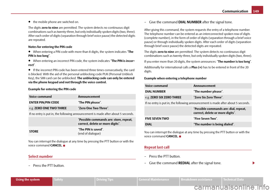
Example for entering the PIN code
You can interrupt the dialogue at any time by pressing the PTT button or with the
voice command CANCEL.
Select number
– Press the PTT button. – Give the command
DIAL NUMBER after the signal tone.
After giving this command, the system re quests the entry of a telephone number.
The telephone number can be entered as an interconnected spoken row of digits
(complete number), in the form of order of digits (separation through a brief voice
pause) or through individually spoken digits. After each order of digits (separation
through brief voice pa use) the detected digits are repeated.
The digits zero to nine are permitted. The system detects no continuous digit
combinations such as twenty-three, but only individually spoken digits (two, three).
If you enter more than 20 digits, the system announces: “ The number is too long”.
Additionally for international calls a Plus (+) has to be entered in front of the 20
digits.
Example when entering a telephone number
You can interrupt the dialogue at any time by pressing the PTT button or with the
voice command CANCEL.
Repeat last call
– Press the PTT button.
– Give the command REDIAL after the signal tone.
Voice commandAnnouncement
ENTER PIN/PIN CODE“The PIN please ”.
e.g. ZERO ONE TWO THREE“Zero One Two Three ”.
If no entry is put in, the following anno uncement is made after about 5 seconds.
“Possible commands are: store, repeat,
correct, delete or more digits ”.
STORE“The PIN is saved ”.
(end of dialogue)
Voice commandAnnouncement
DIAL NUMBER“ The number please ”.
e.g. ZERO SIX ZERO THREE“Zero Six Zero Three ”.
If no entry is put in, the following anno uncement is made after about 5 seconds.
“Possible commands are: dial, repeat,
correct, delete or more digits ”.
FIVE SEVEN TWO“Five Seven Two ”.
DIAL“The number is being dialed ”.
20A5Facelift.book Page 149 Saturday, September 6, 2008 2:13 PM
Page 154 of 304
Communication153
Using the systemSafetyDriving TipsGeneral MaintenanceBreakdown assistanceTechnical Data
The dialogue is always automatically ended after carrying out an operation, e.g.
after erasing the name from the phonebook.
The dialogue of the incoming call is i
mmediately interrupted and you can accept
the call by pressing the button
.
If a voice command is not detected, the system answers with “ Sorry?” and a new
entry can be performed. After the 2nd error the system repeats the aid. After the 3rd
error the answer “ Cancel” is given and the dialogue is ended.
Optimum understanding of the voice commands depends on the following
factors:
•Speak with a normal tone of voice wi thout intonation and excessive voice
pauses.
•Avoid insufficient articulation.
•Close the doors, windows and sliding roof, in order to reduce or stop disturbing
exterior noise.
•It is recommended to speak louder at hi gher speeds, so that the tone of your
voice is louder than the increased surrounding noise.
•During the dialogue avoid additional nois e in the vehicle, e.g. simultaneously
talking occupants.
•Do not speak, if the system makes an announcement.
•The microphone for voice control is in serted in the moulded headliner and
directed to the driver and front passenger. Therefore the driver and the front
passenger can operate the equipment.
WARNING
Pay attention primarily to the traffic situation! As the driver you are fully
responsible for road safety. Use the telephone system only to such an extent,
so that you are in full control of your vehicle at any time.
Note
•Please contact your Škoda Service Partner if there are any points which are not
clear.
•Please also refer to the additional instructions ⇒page 160.
Bluetooth®
The equipment enables the wireless connection to the control unit of a
telephone with Bluetooth® function which supports the rSAP profile.
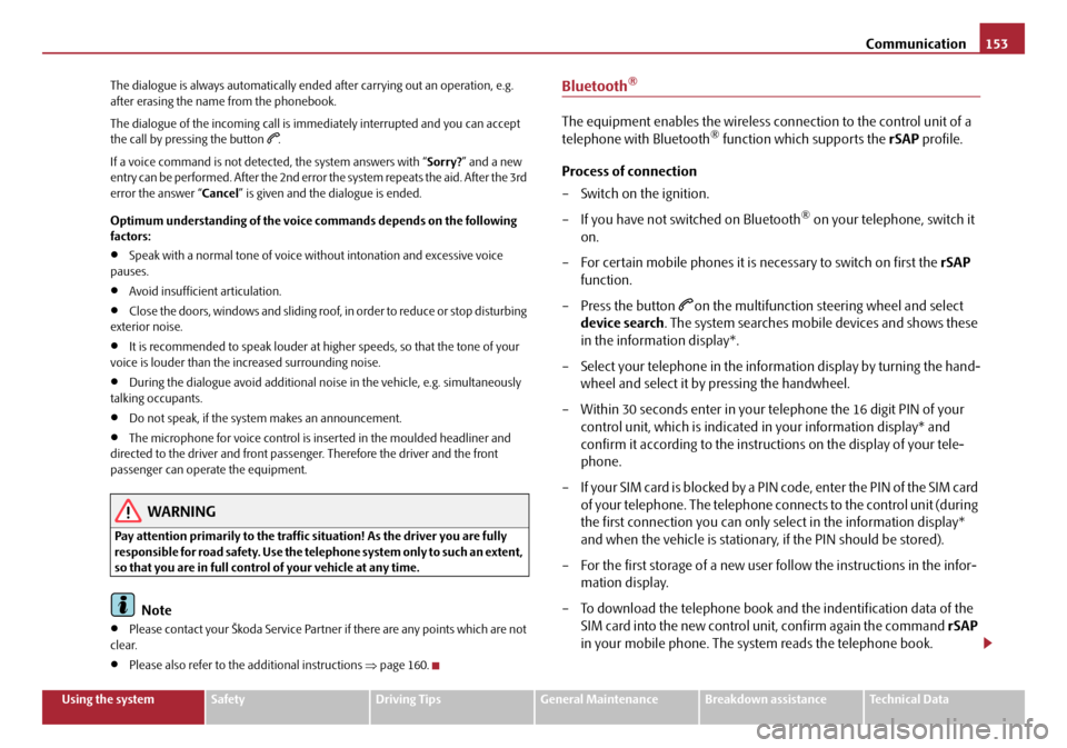
Process of connection
– Switch on the ignition.
– If you have not switched on Bluetooth
® on your telephone, switch it
on.
– For certain mobile phones it is necessary to switch on first the rSAP
function.
–Press the button
on the multifunction st eering wheel and select
device search . The system searches mobile devices and shows these
in the information display*.
– Select your telephone in the information display by turning the hand- wheel and select it by pressing the handwheel.
– Within 30 seconds enter in your telephone the 16 digit PIN of your
control unit, which is indicated in your information display* and
confirm it according to the instructions on the display of your tele-
phone.
– If your SIM card is blocked by a PIN code, enter the PIN of the SIM card of your telephone. The telephone connects to the control unit (during
the first connection you can only se lect in the information display*
and when the vehicle is stationary, if the PIN should be stored).
– For the first storage of a new user follow the instructions in the infor- mation display.
– To download the telephone book and the indentification data of the SIM card into the new control unit, confirm again the command rSAP
in your mobile phone. The sy stem reads the telephone book.
20A5Facelift.book Page 153 Saturday, September 6, 2008 2:13 PM
Page 155 of 304
Communication
154
If you do not want to confirm the command rSAP during each connection of the
telephone to the control unit, then you mu st carry out in the menu of the mobile
phone an authorization using the control unit.
The telephone deregisters from the GSM network and only the control unit ensures
the communication with the network. In the telephone only the interface for Blue-
tooth
® remains active. In this case, you can only select to separate from the device,
switch off the Bluetooth® connection or the number of the emergency call 112.
If the PIN was stored, an automatic selection and connection of the telephone take
place the next time the ignition is swit ched. Check on your mobile phone if the
automatic connection was established.
Connection terminated
The connection of the handsfree-system is terminated by means of Bluetooth
®:
•When removing the key from the ignition lock (during a telephone call, the
connection is disconnected).
•By switching off the Bluetooth® in the mobile phone.
•By selecting “separate telephone” in the menu of the mobile phone.
On vehicles which are fitted out with radio or navigation at the factory, it is possible
to terminate the telephone call after remo ving the key from the ignition lock by
pressing the icon on the touch-screen of the radio
18) or the navigation, see oper-
ating instructions for radio or for navigation.
WARNING
•Pay attention primarily to the traffic situation! As the driver you are fully
responsible for road safety. Use the tele phone system only to such an extent,
so that you are in full control of your vehicle at any time - risk of accident!
•In the event of air transport, the Bluetooth® function of the handsfree-
system must be switched off by a specialist garage!
Note
•In the memory of the control unit, up to three users can be stored, whereby the
handsfree-system can only communicate actively with one user. In the case of
mutual connection with a fourth mobile phone, you must erase one user.
•Not valid for all mobile phones which enable a communication via Bluetooth®.
You can ask at a Škoda Service Partner if your telephone is compatible with the
universal telephone preinstallation GSM II.
•If the telephone book of the mobile ph one contains more than 1 000 entries,
the system announces a failure while loading the telephone book .
•When connecting to the control unit, follow the instructions on your mobile
phone.
•Note that the range of the Bluetooth® connection to the handsfree-system is
optimized in the vehicle interior. The rang e is dependent on local factors, e.g.
obstacles between the devices and interferences with other devices.
18)Does not apply for Radio Swing.
20A5Facelift.book Page 154 Saturday, September 6, 2008 2:13 PM
Page 166 of 304
Passive Safety165
Using the systemSafetyDriving TipsGeneral MaintenanceBreakdown assistanceTechnical Data
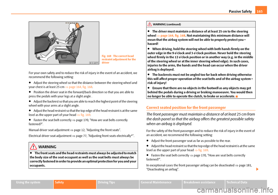
For your own safety and to reduce the risk of injury in the event of an accident, we
recommend the following setting:
•Adjust the steering wheel so that the distance between the steering wheel and
your chest is at least 25 cm ⇒page 164, fig. 168 .
•Position the driver seat in the forward/back direction so that you are able to
press the pedals with your legs at a slight angle .
•Adjust the backrest so that you are able to reach the highest point of the steering
wheel with your arms at a slight angle.
•Adjust the head restraint so that the top edge of the head restraint is at the same
level as the upper part of your head ⇒fig. 169 .
•Fasten the seat belt correctly ⇒page 170, “How are seat belts correctly
fastened?”.
Manual driver seat adjustment ⇒page 12, “Adjusting the front seats”.
Electrical driver seat adjustment ⇒page 77, “Adjusting front seats electrically*”.
WARNING
•The front seats and the head restraints must always be adjusted to match
the body size of the seat occupant as well as the seat belts must always be
correctly fastened in order to provide an optimal protection for you and your
occupants.
•The driver must maintain a distance of at least 25 cm to the steering
wheel ⇒page 164, fig. 168 . Not maintaining this minimum distance will
mean that the airbag system will not be able to properly protect you -
hazard!
•When driving, hold the steering wheel with both hands firmly on the
outer edge in the 9 o'clock and 3 o'clock position. Never hold the steering
wheel firmly in the 12 o'clock position or in another way (e.g. in the middle
of the steering wheel or at the inner steering wheel edge). In such cases,
injuries to the arms, the hands and the head can occur when the driver
airbag is deployed.
•The backrests must not be angled to o far back when driving otherwise
this will affect proper operation of the seat belts and of the airbag system -
risk of injury!
•Ensure that there are no objects in the footwell as any objects may get
behind the pedals during a driving or braking manoeuvre. You would then
no longer be able to operate the clutch, to brake or accelerate.
Correct seated position for the front passenger
The front passenger must maintain a distance of at least 25 cm from
the dash panel so that the airbag offers the greatest possible safety
when an airbag is deployed.
For the safety of the front passenger and to reduce the risk of injury in the event of
an accident, we recommend the following setting:
•Adjust the front passenger seat as far as possible to the rear.
•Adjust the head restraint so that the top edge of the head restraint is at the same
level as the upper part of your head ⇒fig. 169 .
•Fasten the seat belt correctly ⇒page 170, “How are seat belts correctly
fastened?”.
In exceptional cases the front pass enger airbag can be deactivated ⇒page 181,
“Deactivating an airbag”.
Fig. 169 The correct head
restraint adjustment for the
driver
WARNING (continued)
20A5Facelift.book Page 165 Saturday, September 6, 2008 2:13 PM
Page 171 of 304

Seat belts
170
•No two persons (also not children) should ever use a single seat belt
together.
•The maximum protection which seat belts can offer is only achieved if
you are correctly seated ⇒page 164, “Correct seated position”.
•The belt webbing must no t run across solid or fragile objects (e.g. spec-
tacles, ball-point pens, keys etc.) as this may be a cause of injuries.
•Bulky, loose clothing (e.g. a winter coat over a jacket) does not allow you
to be correctly seated and impairs proper operation of the seat belts.
•It is prohibited to use clamps or other objects to adjust seat belts (e.g. for
shortening the belts for smaller persons).
•The lock tongue should only be insert ed into the lock which is the correct
one for your seat. Wrong use of the safety belt will reduce its capacity to
protect and the risk of injury increases.
•The backrests of the front seats must not be tilted too far to the rear
otherwise the seatbelts can lose their effectiveness.
•The belt webbing must always be ke pt clean. Soiled belt webbing may
impair proper operation of the inertia reel ⇒page 217, “Seat belts”.
•The slot of the belt tongue must not be blocked by paper or similar
objects otherwise the belt tongue will not lock in place properly.
•Inspect the seat belts regu larly to ensure they are in good condition. If
you find seat belts which have damage to the seat belt webbing, seat belt
connections, to the inertia reels or to the lock, the relevant safety belt must
be replaced by a specialist garage.
•The seat belts must not be removed or changed in any way. Do not make
an attempt to repair the seat belts yourself.
•Damaged seat belts which have been subjected to stress in an accident
and were therefore stretched, must be replaced - this is best done by a
specialist garage. The anchorage points of the belts must also be inspected.
The anchorage points for the be lts should also be checked.
•In certain countries it is possible to use seat belts which differ in terms of
their operation from the seat belts wh ich are described on the pages which
follow.
How are seat belts correctly fastened?
Fastening three-point seat belts
Fasten your seat belt before starting!
– Correctly adjust the front seat and the head restraint before fastening your seat belt ⇒page 80.
WARNING (continued)
Fig. 173 Routing of webbing
over the shoulders and the
lap belt
Fig. 174 Routing of belt
webbing for an expectant
mother
20A5Facelift.book Page 170 Saturday, September 6, 2008 2:13 PM
Page 172 of 304
Seat belts171
Using the systemSafetyDriving TipsGeneral MaintenanceBreakdown assistanceTechnical Data
– Slowly pull the belt webbing at the to ngue of the lock over your chest
and pelvis ⇒.
– Insert the tongue of the lock into th e seat belt buckle belonging to the
seat until it is heard to lock in place.
– Pull on the belt to check that it has also reliably engaged in the lock.
Each three-point seat belt is equipped with an inertia reel. This inertia reel offers
you complete freedom of movement if the belt is unreeled slowly. If the brakes are
applied suddenly, the inertia reel will block. It also blocks the belts when the car
accelerates, when driving uphill and when cornering.
Expectant mothers must also wear the seat belt ⇒.
WARNING
•The shoulder part of the seat belt must never run across your neck but
must run approximately over the middl e of the shoulder and fit snugly
against the chest. The lap part of the belt must run across the hip and must
never be routed across the stomach. It must always fit snugly ⇒page 170,
fig. 173 . Adjust the belt webbing as required.
•The lap part of the belt should be positioned as low as possible at the
pelvis of an expectant mother in order to avoid exerting any pressure on the
lower abdomen ⇒page 170, fig. 174 .
•Always ensure that the webbing of the seat belts is properly routed. Seat
belts which are not correctly adjusted ca n themselves cause injuries even in
minor accidents.
•A seat belt which is hanging too loose can result in injuries as your body
is moved forward by the kinetic energy produced in an accident and is then
suddenly held firm by the belt.
•Only insert the lock tongue into the lo ck which is the correct one for your
seat. This will affect the protection whic h the belt offers and increase the risk
of an injury.
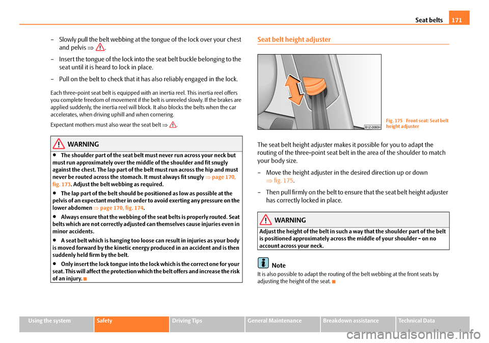
Seat belt height adjuster
The seat belt height adjuster makes it possible for you to adapt the
routing of the three-point seat belt in the area of the shoulder to match
your body size.
– Move the height adjuster in the desired direction up or down ⇒fig. 175 .
– Then pull firmly on the belt to ensure that the seat belt height adjuster
has correctly locked in place.
WARNING
Adjust the height of the belt in such a way that the shoulder part of the belt
is positioned approximately across the middle of your shoulder - on no
account across your neck.
Note
It is also possible to adapt the routing of the belt webbing at the front seats by
adjusting the height of the seat.
Fig. 175 Front seat: Seat belt
height adjuster
20A5Facelift.book Page 171 Saturday, September 6, 2008 2:13 PM