SKODA OCTAVIA 2008 2.G / (1Z) Manual PDF
Manufacturer: SKODA, Model Year: 2008, Model line: OCTAVIA, Model: SKODA OCTAVIA 2008 2.G / (1Z)Pages: 304, PDF Size: 17.69 MB
Page 71 of 304
Lights and Visibility
70
Fast wipe
– Position the lever up into position .
Automatic wipe/wash for windscreen
– Pull the lever towards the steering wheel into sprung position , the wash system sprays immediately, the windscreen wiper starts wiping
a little later. The wash system and the windscreen wiper operate
simultaneously at a speed of more than 120 km/h.
– Release the lever. The windscreen wash system stops and the wiper continues for another 3 - 4 wiper stro kes (depending on the period of
spraying of the windscreen). At a speed of more than 2 km/h, the wiper
wipes once again* 5 seconds after the last wiper stroke in order to
wipe the last drops from the windsc reen. This function can be acti-
vated/deactivated by a specialist garage.
Rain sensor*
– Move the lever into position .
– You can set the sensitivity of the sensor individually with switch .
Wiping the rear window pane*
– Push the lever away from the steering wheel into position - the widescreen wiper will operate every 6 seconds.
Automatic wipe/wash for the rear window pane*
– Press the lever from the steering wheel forward into the sprung posi- tion , the wash system sprays immediately, the windscreen wiper
starts wiping a little later. As long as you hold the lever in this position,
the wiper operates as well as the wash system.
– Letting go of the lever will cause the windscreen wash system to stop and the wiper to continue for anot her 2 - 3 wiper strokes (depending
on the period of spraying of the windscreen). The lever will stay in
position after releasing it . Switching windscreen wipers off
– Move the lever back into its home position .
After the windscreen wiper switches off each
time or the ignition switches off for
the third time, the position of the windscreen wiper changes, this counteracts an
early fatigue of the wiper rubbers.
The windscreen wipers and the wash system only operate if the ignition is switched
on and the bonnet is closed
10).
If the intermittent wipe is switched on, the intervals are also controlled depending
on speed.
The rain sensor* automatically regulates the break between the individual wiper
strokes depending on the intensity of the rain.
The rear window will be wiped again if the front window wipers are on when
reverse gear is selected.
The windscreen washer nozzles are heated* when the ignition is switched on.
Top up with wash liquid ⇒page 235.
Winter position
If the windscreen wipers are in rest posi tion, they cannot be folded out from the
windscreen. For this reason we recommend adjusting the windscreen wipers in
winter so that they can be folded out fr om the windscreen easily. You can set this
rest position as follows:
•Switch on the windscreen wipers.
•Switch off the ignition. The windscreen wipers remain in the position in which
they were when switching off the ignition.
You can also use the service position ⇒page 71 as a winter position.
A3
A5
A1
AA
A6
A7
A6
10)On vehicles which do not have a contact swit ch for the bonnet, the windshield wiper and
wash system operates also when the bonnet is opened.
A0
20A5Facelift.book Page 70 Saturday, September 6, 2008 2:13 PM
Page 72 of 304
Lights and Visibility71
Using the systemSafetyDriving TipsGeneral MaintenanceBreakdown assistanceTechnical Data
WARNING
•Properly maintained windscreen wiper blades are essential for clear visi-
bility and safe driving ⇒page 71.
•Do not use the windscreen washer sy stem at low temperatures, without
heating the windscreen beforehand. Otherwise the window cleaner could
freeze on the windscreen and re strict the view to the front.
•The rain sensor only operates as a support. The driver is not released
from the responsibility to set the function of the windscreen wipers manu-
ally depending on the visibility conditions.
Caution
In frosty weather, please first of all check whether the windscreen wiper blades are
not frozen to the windscreen before swit ching them on. Switching on windscreen
wipers when the blades are frozen to the windscreen may result in damage both to
the blades and the motor of the windscreen wipers!
Note
•If the slower or the faster wiper setting is switched on ⇒page 69, fig. 70
and the vehicle speed decreases to below 4 km/h, the lower wiper step is switched
on automatically. At a speed increase of more than 8 km/h the previous wiper
setting is esta blished again.
•If there is an obstacle on the windscre en, the wiper will try to push away the
obstacle. If the obstacle continues to block the wiper, th e wiper stops after 5 cycles,
in order to avoid a damage to the wiper. Remove the obstacle and and switch on
the wiper again.
Headlight cleaning system*
The headlights are being cleaned after the windscreen has been sprayed for the first
time and fifth time, the low beam or ma in beam are switched on and the wind-
screen wiper lever was he ld in the position ⇒page 69, fig. 70 for about 1
second. The headlight washer nozzles are moved forward out of the bumper by the water
pressure for cleaning the headlights.
You should remove stubborn dirt (such
as insect residues) from the headlight
lenses at regular intervals, for example when refuelling. Please refer to the following
guidelines ⇒page 214, “The headlight lenses”.
You should remove any snow from the fixtures of the washer nozzles and clear ice
in winter with a de-icing spray in order to ensure proper operation of the cleaning
system.
Replacing wiper blades for the windscreen wipers
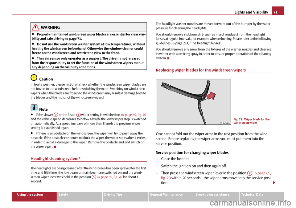
One cannot fold out the wiper arms in the rest position from the wind-
screen. Before replacing the wiper arms you must put them into the
service position.
Service position for changing wiper blades
– Close the bonnet.
– Switch the ignition on and then again off.
– Then press the windscreen wiper lever in the position ⇒page 69,
fig. 70 within 20 seconds - the wiper arms move into the service posi-
tion.
A2A3
A5
Fig. 71 Wiper blade for the
windscreen wiper
A4
20A5Facelift.book Page 71 Saturday, September 6, 2008 2:13 PM
Page 73 of 304
Lights and Visibility
72
Taking off the wiper blade
– Fold windscreen wiper arm out from the windscreen and position the wiper blade at right angles to the wiper arm ⇒.
– Take off the wiper blade in direction of arrow ⇒page 71, fig. 71
⇒ .
Attaching a wiper blade
– Push the new wiper blade over the wiper arm and turn the wiper blade into the vertical position.
– Check whether the wiper blade is correctly attached.
– Fold the windscreen wiper arms on to the window and switch on the
ignition. By pressing the window wi per lever into the sprung position
⇒ page 71, fig. 71 or when driving at a speed greater than 4 km/h,
the windscreen wiper arms move back into the rest position.
Wiper blades in proper condition are esse ntial to obtain good visibility. Wiper
blades should not be allowed to become dirtied by dust, insect remains and
preserving wax.
Juddering or smearing of the wiper blades could then be due to wax residues left
on the windscreen by vehicle washing in automatic vehicle wash systems. It is
therefore important to degrease the lips of the wiper blades after every pass
through an automatic vehicle wash system .
WARNING
•The ignition must not be switched on if the front windscreen wiper arms
are folded out. The wiper blades would move back into their rest position
and while doing so damage th e paintwork of the bonnet.
•If the windscreen wipers are handled carelessly, there is a risk of damage
to the windscreen.
•You should clean the wiper blades regularly with a windscreen cleaner in
order to avoid any smears. Clean a wiper bl ade with a sponge or cloth if it is
very dirty, for example from insect residues.
•Replace the wiper blades once or twice a year for safety reasons. The
wiper blades are available from Škoda Service Partners.
Replacing the wiper blade on the rear window wiper
Taking off the wiper blade
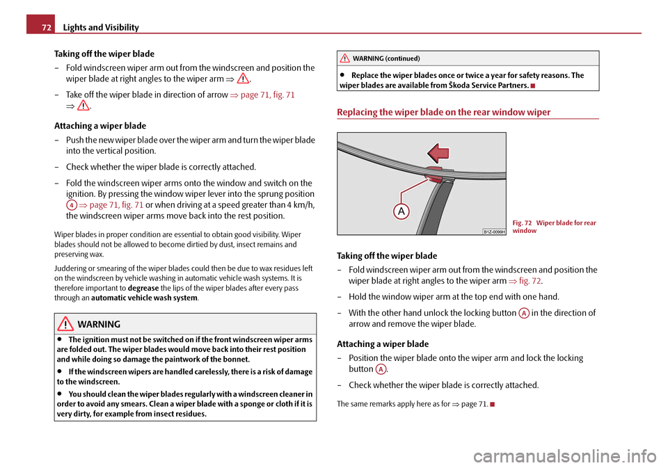
– Fold windscreen wiper arm out from the windscreen and position the wiper blade at right angles to the wiper arm ⇒fig. 72 .
– Hold the window wiper arm at the top end with one hand.
– With the other hand unlock the locking button in the direction of arrow and remove the wiper blade.
Attaching a wiper blade
– Position the wiper blade onto the wiper arm and lock the locking button .
– Check whether the wiper blade is correctly attached.
The same remarks apply here as for ⇒page 71.
A4
WARNING (continued)
Fig. 72 Wiper blade for rear
window
AA
AA
20A5Facelift.book Page 72 Saturday, September 6, 2008 2:13 PM
Page 74 of 304
Lights and Visibility73
Using the systemSafetyDriving TipsGeneral MaintenanceBreakdown assistanceTechnical Data
Rear-view mirror
Manual dimming interior rear-view mirror
Basic setting
– Pull the lever on the bottom edge of the mirror forward.
Dimming mirror
– Pull the lever on the bottom edge of the mirror back.
Automatic dimming interior mirror*
Switching on the automatic dimming
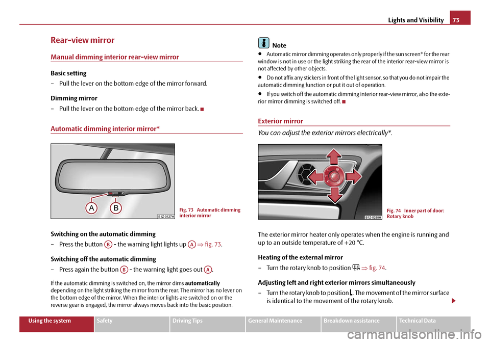
– Press the button - the warning light lights up ⇒fig. 73 .
Switching off the automatic dimming
– Press again the button - the warning light goes out .
If the automatic dimming is switched on, the mirror dims automatically
depending on the light striking the mirror from the rear. The mirror has no lever on
the bottom edge of the mirror. When the interior lights are switched on or the
reverse gear is engaged, the mirror alwa ys moves back into the basic position.
Note
•Automatic mirror dimming operates only pr operly if the sun screen* for the rear
window is not in use or the light striking th e rear of the interior rear-view mirror is
not affected by other objects.
•Do not affix any stickers in front of the li ght sensor, so that you do not impair the
automatic dimming function or put it out of operation.
•If you switch off the automatic dimming interior rear-view mirror, also the exte-
rior mirror dimming is switched off.
Exterior mirror
You can adjust the exterior mirrors electrically*.
The exterior mirror heater only oper ates when the engine is running and
up to an outside temperature of +20 °C.
Heating of the external mirror
– Turn the rotary knob to position
⇒ fig. 74 .
Adjusting left and right exterior mirrors simultaneously
– Turn the rotary knob to position
. The movement of the mirror surface
is identical to the movement of the rotary knob.
Fig. 73 Automatic dimming
interior mirror
ABAA
ABAA
Fig. 74 Inner part of door:
Rotary knob
20A5Facelift.book Page 73 Saturday, September 6, 2008 2:13 PM
Page 75 of 304
Lights and Visibility
74
Adjusting the right-hand exterior mirror
– Turn the rotary knob to position
. The movement of the mirror
surface is identical to the mo vement of the rotary knob.
Switching off operating control
– Turn the rotary knob to position
.
Folding in both exterior mirrors
– Turn the rotary knob to position
.
Lowerable exterior mirror* with the aid of the key for remote control
– If all the windows are closed, press the unlock button on the remote control ⇒page 50, fig. 49 for approx. 2 seconds.
Tilting surface of front pa ssenger exterior mirror*
When the rotary knob is in position
⇒ page 73, fig. 74 and the reverse gear is
engaged, the surface of the mirror tilts down slightly. This provides an aid in seeing
the kerb of the pavement when parking the car.
The mirror returns back into its initial po sition, after the rotary knob is moved out
of the position
and put into another position or if the speed is more than 15 km/h.
Memory for exterior mirrors*
On vehicles fitted with a memory for the driver seat, the relevant setting of the exte-
rior mirror is also stored automatically when the seat position is stored ⇒page 77.
WARNING
•Convex (curved outward) or spherical (differently curved) exterior
mirrors increase the vision field. Th ey do, however, make objects appear
smaller in the mirror. These mirrors are only of limited use, therefore, for
estimating distances to the following vehicles.
•Use whenever possible the interior rear mirror, for estimating the
distances to the fo llowing vehicles.
Note
•If the exterior mirrors are folded in using the remote control* of the vehicle key,
these are folded back into the driving po sition after switching on the ignition.
•If the exterior mirrors are folded in using the rotary knob ⇒page 73, fig. 74 ,
they can only be folded back into th e driving position using the rotary knob.
•If the exterior mirrors were folded in using the remote control* of the vehicle
key and if the rotary knob was in the fold -in position before switching on the igni-
tion, the mirrors remain in the fold-in positi on the next time the ignition is switched
on. Folding back into the driving position is performed by actuating the rotary knob
in a different position from the fold-in position.
•Do not touch the surfaces of the exterior mirrors if the exterior mirror heater is
switched on.
•You can set the exterior mirrors by hand, if the power setting function fails at any
time by pressing on the ed ge of the mirror surface.
•Contact your specialist garage if a fault exists with the power setting of the exte-
rior mirrors.
Automatic dimming exterior mirror*
The exterior mirrors are dimmed together with the interior mirror. If the automatic
dimming is switched on, the mirror dims automatically depending on the light
striking the mirror from the rear.
When the interior lights are switched on or the reverse gear is engaged, the mirror
always moves back into the basic position (not dimmed).
Note
•Automatic mirror dimming operates only properly if the sun screen* for the rear
window is not in use or the light striking the rear of the interior rear-view mirror is
not affected by other objects.
•Do not affix any stickers in front of the li ght sensor, so that you do not impair the
automatic dimming function or put it out of operation.
A3
20A5Facelift.book Page 74 Saturday, September 6, 2008 2:13 PM
Page 76 of 304

Lights and Visibility75
Using the systemSafetyDriving TipsGeneral MaintenanceBreakdown assistanceTechnical Data
•If you switch off the automatic dimming interior rear-view mirror, also the exte-
rior mirror dimming is switched off.
20A5Facelift.book Page 75 Saturday, September 6, 2008 2:13 PM
Page 77 of 304
Seats and Stowage
76
Seats and Stowage
Front seats
Basic information
The front seats have a wide range of different settings and can thus be matched to
the physical characteristics of the driver and front passenger. Correct adjustment of
the seats is particularly important for
•safely and quickly reaching the controls,
•a relaxed, fatigue-free body position,
•achieving the maximum protection offere d by the seat belts and the airbag
system.
WARNING
•Never transport more occupants than the maximum seating in the
vehicle.
•Each occupant must correctly fasten the seat belt belonging to the seat.
Children must be fastened ⇒page 184, “Transporting children safely” with
a suitable restraint system.
•The front seats and the head restraints must always be adjusted to match
the body size of the seat occupant as well as the seat belts must always be
correctly fastened in order to provide an optimal protection for you and your
occupants.
•Always keep your feet in the footwell when the car is being driven - never
place your feet on the instrument panel, out of the window or on the
surfaces of the seats. This is particularly important for the front seat
passenger. You will be exposed to increased risk of injury if it becomes
necessary to apply the brake or in the event of an accident. If an airbag is
deployed, you may suffer fatal injuries when adopting an incorrect seated
position!
•It is important for the driver and front passenger to maintain a distance
of at least 25 cm from the steering wheel or dash panel. Not maintaining this minimum distance will mean
that the airbag system will not be able to prop-
erly protect you - hazard! The front seats and the head restraints must
always also be correctly adjusted to match the body size of the occupant.
•Ensure that there are no objects in the footwell as any objects may get
behind the pedals during a driving or braking manoeuvre. You would then
no longer be able to operate the clutch, to brake or accelerate.
Adjusting the front seats
Adjusting a seat in a forward/back direction
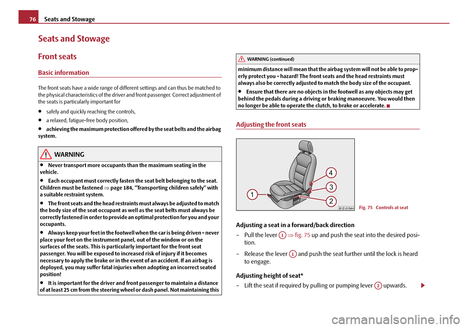
– Pull the lever ⇒fig. 75 up and push the seat into the desired posi-
tion.
– Release the lever and push the seat further until the lock is heard to engage.
Adjusting height of seat*
– Lift the seat if required by pulling or pumping lever upwards.
WARNING (continued)
Fig. 75 Controls at seat
A1
A1
A2
20A5Facelift.book Page 76 Saturday, September 6, 2008 2:13 PM
Page 78 of 304
Seats and Stowage77
Using the systemSafetyDriving TipsGeneral MaintenanceBreakdown assistanceTechnical Data
– Lower the seat if required by pushing or pumping lever down-
wards.
Adjust the angle of the seat backrest
– Relieve any pressure on the backrest (do not lean on it) and turn the handwheel ⇒page 76, fig. 75 to adjust the desired angle of the
backrest.
Adjusting lumbar support*
– Turn the handwheel until you have set the most comfortable
curvature of the seat upholstery in the area of your spine.
The driver's seat should be adjusted in such a way that the pedals can be pressed
to the floor with slightly bent legs.
The backrest on the driver's seat should be adjusted in such a way that the upper
point of the steering wheel can be easi ly reached with slightly bent arms.
WARNING
•Only adjust the driver seat when the ve hicle is stationary - risk of injury!
•Take care when adjusting the seat! Adjusting the seat without care can
lead to bruises or injuries.
•The backrests must not be angled too far back when driving otherwise
this will affect proper operation of the seat belts and of the airbag system -
risk of injury!
Adjusting front seats electrically*
Adjusting seats
Adopt the correct seated position before setting ⇒page 76.
Adjusting a seat in a forward/back direction
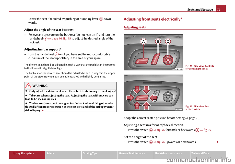
– Press the switch ⇒fig. 76 forwards or backwards ⇒fig. 77 .
Set the height of the seat
– Press the switch ⇒fig. 76 upwards or downwards.
A2
A3
A4
Fig. 76 Side view: Controls
for adjusting the seat
Fig. 77 Side view: Seat
setting switch
AAA1
AA
20A5Facelift.book Page 77 Saturday, September 6, 2008 2:13 PM
Page 79 of 304
Seats and Stowage
78
Adjust the angle of the seat
– Press the switch at the front ⇒page 77, fig. 77 or at the back
⇒ page 77, fig. 77 .
Adjusting the seat backrest
– Press the switch ⇒page 77, fig. 76 in the direction of the desired
setting.
Adjusting lumbar support
– Press the switch front ⇒page 77, fig. 76 in order to enlarge the
curvature of the lumbar support.
– Press the switch rear in order to reduce the curvature of the lumbar support.
– Press the switch top in order to adjust the curvature of the lumbar support higher.
– Press the switch bottom in order to adjust the curvature of the lumbar support lower.
Switch is operated in order to move the seat up/down and forward/back, while
switch is operated in order to move the backrest forward or back.
WARNING
•Only adjust the driver seat when the ve hicle is stationary - risk of injury!
•Caution when adjusting the seat! You may suffer injuries or bruises as a
result of adjusting the seat without paying proper attention.
•In view of the fact that the seats can also be adjusted when the ignition is
switched off (even when ignition key withdrawn), you should never leave
children unattended in the car.
•The backrests must not be angled too far back when driving otherwise
this will affect proper operation of th e seat belts and of the airbag system -
risk of injury!
Note
If the movement of the seat is inadvertently interrupted during an adjustment, once
again press the switch in the appropriate direction and continue with the adjust-
ment of the seat to the end.
Storing setting
Storing seat and exterior mirror settings for driving forward
– Switch on the ignition.
– Adjust the seat ⇒page 77.
– Adjust both exterior mirrors ⇒page 73.
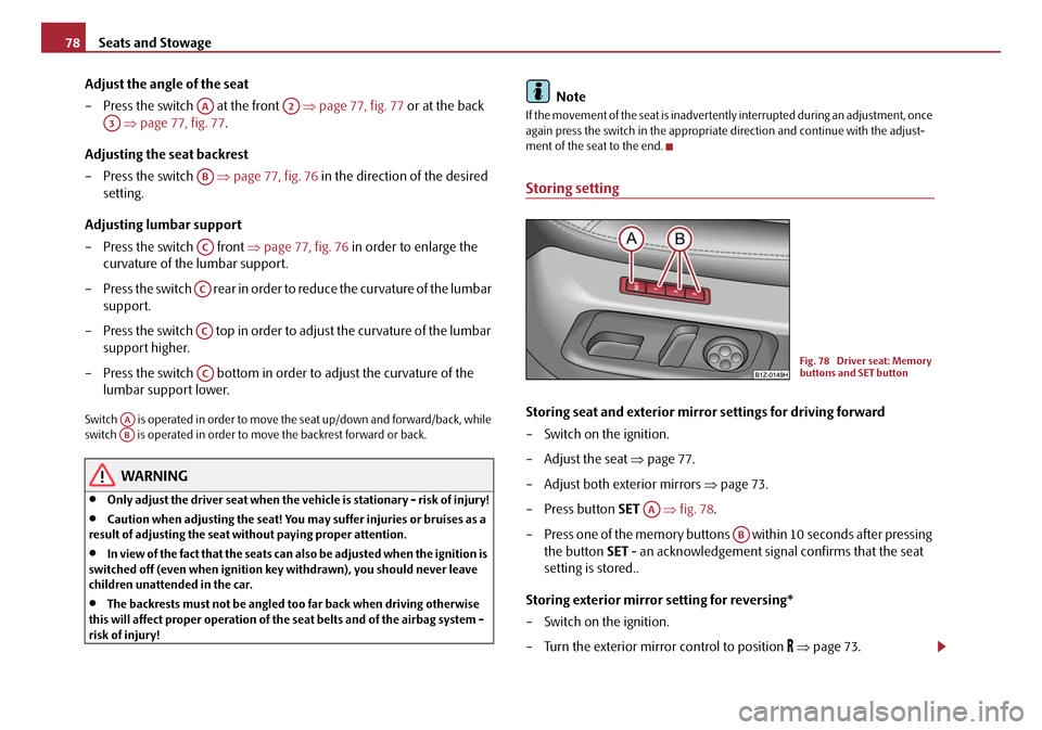
– Press button SET ⇒fig. 78 .
– Press one of the memory buttons within 10 seconds after pressing the button SET - an acknowledgement signal confirms that the seat
setting is stored..
Storing exterior mirror setting for reversing*
– Switch on the ignition.
– Turn the exterior mirror control to position
⇒ page 73.
AAA2
A3
AB
AC
AC
AC
AC
AAAB
Fig. 78 Driver seat: Memory
buttons and SET button
AA
AB
20A5Facelift.book Page 78 Saturday, September 6, 2008 2:13 PM
Page 80 of 304
Seats and Stowage79
Using the systemSafetyDriving TipsGeneral MaintenanceBreakdown assistanceTechnical Data
– Engage reverse gear.
– Move the right exterior mirror into the desired position ⇒page 73.
– Take the vehicle out of gear. The set position of the exterior mirror is stored.
Memory buttons
Memory for the seat offers the possibility to store the individual driver seat and
external mirror position. An individual posi tion can be allocated to each of the three
memory buttons ⇒page 78, fig. 78 , that is three in tota l. After pressing the
corresponding memory button , the seat and the exterior mirror are automati-
cally moved into the positions which have been allocated to this button ⇒page 79.
Emergency Off
You can interrupt the setting operation at any time, if you operate any button of the
driver seat.
Note
•When storing settings with the memory buttons, we recommend that you begin
with the front button and assign a memo ry button to each additional driver.
•Each new setting stored with the same button erases the previous setting.
•Each time you store the seat and exterior mirror settings for driving forward you
also have to re-store the individual setting of the exterior mirror on the passenger
side for reversing.
Assigning remote control to the memory buttons
After storing the settings of the seat and exterior mirrors, you have 10
seconds in order to assign the remote control to the appropriate memory
button.
– Withdraw the ignition key.
– Press the button for unlocking the vehicle ⇒page 50. The setting is
stored with the memory button which you have selected.
If you wish to be able to retrieve the settings which are stored in the memory by also
using the remote control, you have to assign the remote control to a memory
button in each case.
If you wish, you can obtain an additional key with radio remote control from a
Škoda dealer and then assign the radio re mote control to another memory button.
Note
•If the remote control had previously been assigned to another memory button,
this setting is then erased by the new assignment.
•If you assign the remote control to a memory button which has already been
assigned to a remote control, the old assi gnment is also replaced by a new assign-
ment in this case.
•The assignment of the remote control to a memory button is retained, however,
after reassigning the seats and exterior mirrors.
Retrieving settings of the seat and mirrors
You can retrieve the stored settings either with the memory buttons
or with the remote control*.
Retrieving settings with memory buttons
– In order to retrieve the stored setting, you have two possibilities:
– One-touch automatic memory: Briefly press the desired memory
button ⇒page 78, fig. 78 . The seat and exterior mirror are moved
automatically into the stored position s (this applies only if the ignition
is switched on and the speed is less than 5 km/h).
– Memory keying : Press and hold the desired memory button
pressed long enough until the seat and the exterior mirror are moved
into the stored positions.
ABAB
AB
AB
20A5Facelift.book Page 79 Saturday, September 6, 2008 2:13 PM