change key battery SKODA OCTAVIA 2008 2.G / (1Z) Owner's Manual
[x] Cancel search | Manufacturer: SKODA, Model Year: 2008, Model line: OCTAVIA, Model: SKODA OCTAVIA 2008 2.G / (1Z)Pages: 304, PDF Size: 17.69 MB
Page 21 of 304

Instruments and Indicator/Warning Lights
20
Service Interval Display
Depending on the equipment installed in the vehicle, the text can differ on the
display.
Service Interval Display
Before the next service interval a key symbol
and the remaining kilometers are
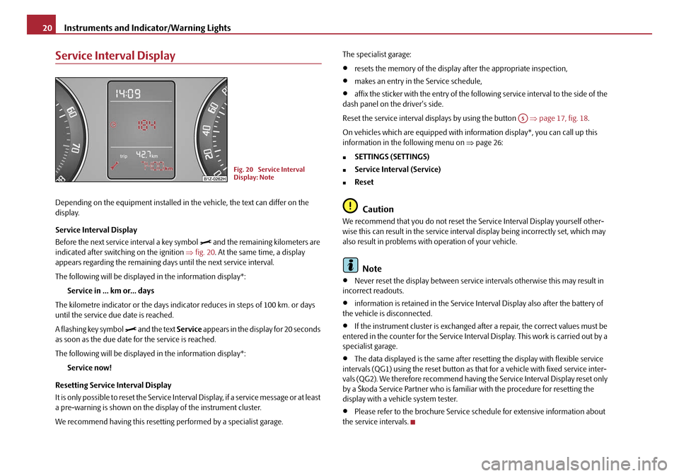
indicated after switching on the ignition ⇒fig. 20 . At the same time, a display
appears regarding the remaining days until the next service interval.
The following will be displayed in the information display*:
Service in ... km or... days
The kilometre indicator or the days indica tor reduces in steps of 100 km. or days
until the service due date is reached.
A flashing key symbol
and the text Service appears in the display for 20 seconds
as soon as the due date for the service is reached.
The following will be displayed in the information display*:
Service now!
Resetting Service Interval Display
It is only possible to reset the Service Interval Display, if a service message or at least
a pre-warning is shown on the display of the instrument cluster.
We recommend having this resetting performed by a specialist garage. The specialist garage:
•resets the memory of the display after the appropriate inspection,
•makes an entry in the Service schedule,
•affix the sticker with the entry of the following service interval to the side of the
dash panel on the driver's side.
Reset the service interval displays by using the button ⇒page 17, fig. 18 .
On vehicles which are equipped with in formation display*, you can call up this
information in the following menu on ⇒page 26:
�„SETTINGS (SETTINGS)
�„Service Interval (Service)
�„Reset
Caution
We recommend that you do not reset the Service Interval Display yourself other-
wise this can result in the service interval display being incorrectly set, which may
also result in problems with operation of your vehicle.
Note
•Never reset the display between service intervals otherwise this may result in
incorrect readouts.
•information is retained in the Service Interval Display also after the battery of
the vehicle is disconnected.
•If the instrument cluster is exchanged afte r a repair, the correct values must be
entered in the counter for the Service Interva l Display. This work is carried out by a
specialist garage.
•The data displayed is the same after resetting the display with flexible service
intervals (QG1) using the reset button as th at for a vehicle with fixed service inter-
vals (QG2). We therefore recommend having the Service Interval Display reset only
by a Škoda Service Partner who is familiar with the procedure for resetting the
display with a vehicle system tester.
•Please refer to the brochure Service schedule for extensive information about
the service intervals.
Fig. 20 Service Interval
Display: Note
A5
20A5Facelift.book Page 20 Saturday, September 6, 2008 2:13 PM
Page 53 of 304

Unlocking and locking
52
•Angle of the vehicle* ⇒page 52,
•Vehicle interior* ⇒page 52,
•A drop in voltage of the on-board power supply.
An alarm is immediately triggered if either of the two battery terminals is discon-
nected while the anti-theft alarm system is activated.
How is the alarm switched off?
You switch the alarm off if you unlock the car with the radio remote control in the
key or if you switch the ignition on.
Note
•The working life of the alarm siren is 6 years. More detailed information is avail-
able from your Škoda Service Partner.
•Before leaving the car, check that al l the doors, windows and the electric
sliding/tilting roof* are properly closed in order to ensure that the anti-theft alarm
system is fully operational.
•Coding of the radio remote control and the receptor part precludes the use of
the radio remote control from other vehicles.
Interior monitor* and Towing protection monitoring*
Switch off the interior monitor and towing protection monitoring
– Switch off the ignition.
– Open the driver door.
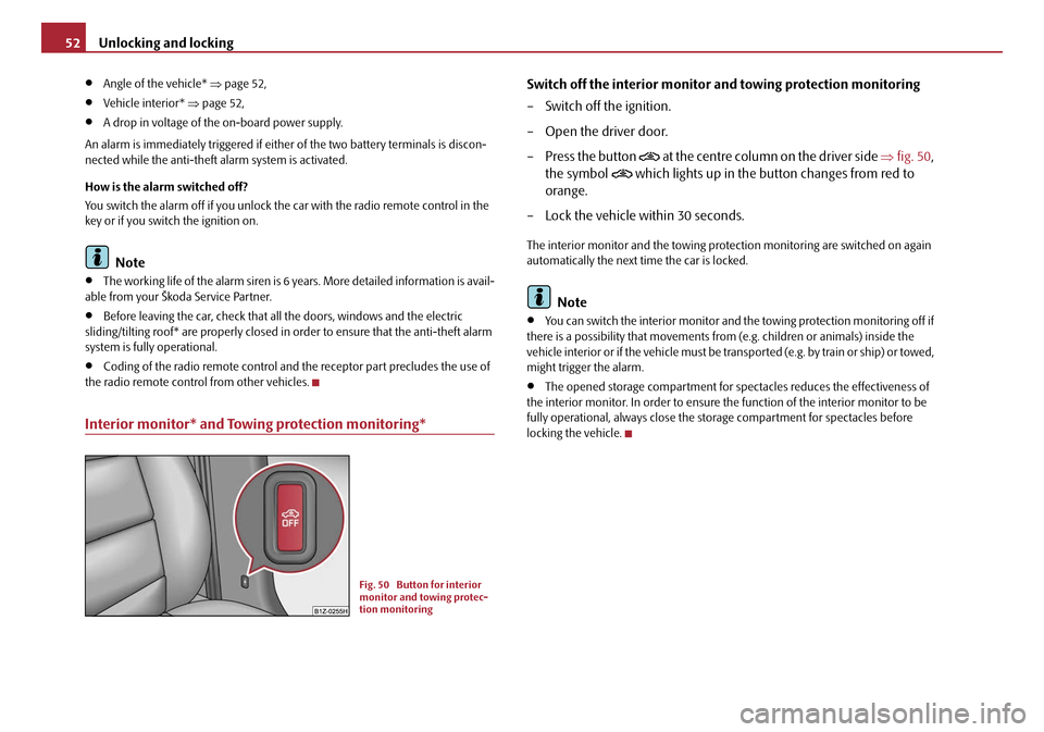
– Press the button
at the centre c olumn o n the dr iver s ide ⇒fig. 50 ,
the symbol
which lights up in the button changes from red to
orange.
– Lock the vehicle within 30 seconds.
The interior monitor and the towing protec tion monitoring are switched on again
automatically the next time the car is locked.
Note
•You can switch the interior monitor and th e towing protection monitoring off if
there is a possibility that movements from (e.g. children or animals) inside the
vehicle interior or if the vehicle must be tr ansported (e.g. by train or ship) or towed,
might trigger the alarm.
•The opened storage compartment for spectacles reduces the effectiveness of
the interior monitor. In order to ensure the function of the interior monitor to be
fully operational, always close the storage compartment for spectacles before
locking the vehicle.
Fig. 50 Button for interior
monitor and towing protec-
tion monitoring
20A5Facelift.book Page 52 Saturday, September 6, 2008 2:13 PM
Page 99 of 304

Seats and Stowage
98
WARNING
•Take care when using the cigarette lighter! Not paying proper attention
or incorrect use the cigarette lighter in an uncontrolled manner may result in
burns.
•The cigarette lighter and the power so cket also operates when the igni-
tion is switched off or the ignition key withdrawn. You should therefore
never leave children unattended in the vehicle.
Caution
Always use matching plugs to av oid damaging the power socket.
Note
•Connecting electrical components when the engine is not running will
drain the battery of the vehicle - risk of battery draining!
•Further information ⇒page 243, “Accessories, changes and replacement of
parts”.
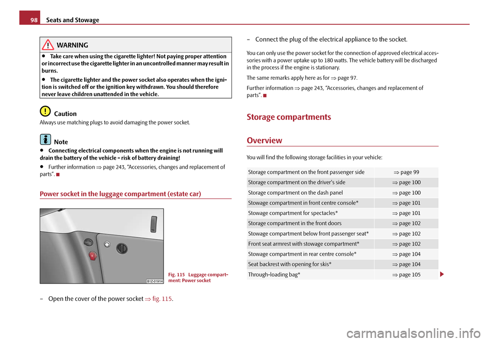
Power socket in the luggage compartment (estate car)
– Open the cover of the power socket ⇒fig. 115 . – Connect the plug of the electr
ical appliance to the socket.
You can only use the power socket for the connection of approved electrical acces-
sories with a power uptake up to 180 watts. The vehicle battery will be discharged
in the process if the engine is stationary.
The same remarks apply here as for ⇒page 97.
Further information ⇒page 243, “Accessories, changes and replacement of
parts”.
Storage compartments
Overview
You will find the following stor age facilities in your vehicle:
Fig. 115 Luggage compart-
ment: Power socket
Storage compartment on the front passenger side⇒page 99
Storage compartment on the driver's side⇒page 100
Storage compartment on the dash panel⇒page 100
Stowage compartment in front centre console*⇒page 101
Stowage compartment for spectacles*⇒page 101
Storage compartment in the front doors⇒page 102
Stowage compartment below front passenger seat*⇒page 102
Front seat armrest with stowage compartment*⇒page 102
Stowage compartment in rear centre console*⇒page 104
Seat backrest with opening for skis*⇒page 104
Through-loading bag*⇒page 105
20A5Facelift.book Page 98 Saturday, September 6, 2008 2:13 PM
Page 123 of 304

Heating and air conditioning system
122
The transmitter and the battery are housed in the housing of the remote control.
The receiver is located in the interior of the car.
If the battery is properly charged, the ef fective range is up to 600 m. For switching
on or off the auxiliary heating, hold the remote control vertically with the antenna
⇒ page 121, fig. 142 towards the top. You must not cover over the antenna with
the fingers or the palm of the hand. Obstacles between the remote control and the
vehicle, bad weather conditio ns and a weaker battery can clearly reduce the range.
The auxiliary heating can only be switched on or off with the remote control, if the
distance between the remote control and the vehicle is at least 2 m.
Warning light in the remote control
The warning light in the remote control ⇒page 121, fig. 142 indicates after a
keystroke if the remote control signal was received by the auxiliary heating and if
the battery is adequately charged.Caution
There are electronic components in the remote control, protect the remote control
against water, severe shoc ks and direct sun rays.
Changing the battery of the radio remote control
If the warning light of the remote control indicates a weak or discharged
battery, ⇒page 121, fig. 142 , it must be replaced. The battery is located
under a cover on the back of the remote control.
– Place a coin into the gap of the battry cover and by turning to the left, unlock the cover.
– Change the battery, insert the cover and lock it by turning to the right.
For the sake of the environment
Dispose of an old battery in accord ance with environmental regulations.
Note
•Pay attention to the correct polarity when changing the battery.
•The replacement battery must have the same specification as the original
battery.
Display warning lightImportance
Lights up green for 2 seconds.The auxiliary heating was switched on.
Lights up red for 2 seconds.The auxiliary heating was switched off.
Slowly flashes green for 2 seconds.The ignition signal was not received.
Quickly flashes green for 2 seconds.The auxiliary heating is blocked, e. g
because the tank is nearly empty or
there is a fault in the auxiliary heating.
Flashes red for 2 seconds.The switch off signal was not received.
Lights up orange for 2 seconds, then
green or red.The battery is weak, however the
switching on or off signal was received.
Lights up orange for 2 seconds, then
flashes green or red.The battery is weak, however the
switching on or off signal was not
received.
Flashes orange for 5 seconds.The battery is discharged, however the
switching on or off signal was not
received.
AA
20A5Facelift.book Page 122 Saturday, September 6, 2008 2:13 PM