warning light SKODA OCTAVIA 2012 3.G / (5E) Owners Manual
[x] Cancel search | Manufacturer: SKODA, Model Year: 2012, Model line: OCTAVIA, Model: SKODA OCTAVIA 2012 3.G / (5E)Pages: 222, PDF Size: 13.52 MB
Page 178 of 222
Brake fluid changeFirst read and observe the introductory information and safety warn-
ings
on page 169.
Brake fluid absorbs moisture. Over time it therefore absorbs moisture from the
environment.
Excessive water in the brake fluid may be the cause of corrosion in the brake sys-
tem.
The water content lowers the boiling point of the brake fluid.
The brake fluid must comply with the following standards or specifications: › VW 50114;
› FMVSS 116 DOT4.
WARNINGDo not use used brake fluid - the function of the brake system may be im-
paired - risk of accident!
CAUTION
Brake fluid damages the paintwork of the vehicle.
Note
The brake fluid is replaced as part of a proscribed Inspection service carried out by
a ŠKODA Partner.
Windscreen washer system
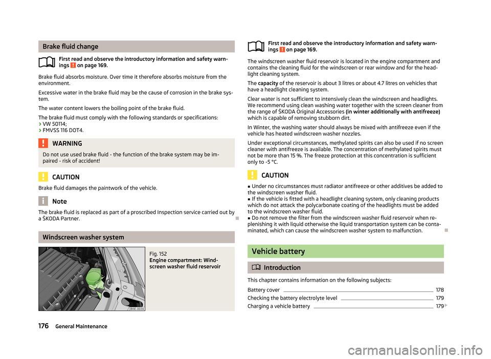
Fig. 152
Engine compartment: Wind-
screen washer fluid reservoirFirst read and observe the introductory information and safety warn-
ings on page 169.
The windscreen washer fluid reservoir is located in the engine compartment and
contains the cleaning fluid for the windscreen or rear window and for the head-
light cleaning system.
The capacity of the reservoir is about 3 litres or about 4.7 litres on vehicles that
have a headlight cleaning system.
Clear water is not sufficient to intensively clean the windscreen and headlights.
We recommend using clean washing water together with the screen cleaner from
the range of ŠKODA Original Accessories (in winter additionally with antifreeze)
which is capable of removing stubborn dirt.
In Winter, the washing water should always be mixed with antifreeze even if the
vehicle has heated windscreen washer nozzles.
Under exceptional circumstances, methylated spirits can also be used if no screen
cleaner with antifreeze is available. The concentration of methylated spirits must
not be more than 15 %. The freeze protection at this concentration is sufficient
only to -5 °C.
CAUTION
■ Under no circumstances must radiator antifreeze or other additives be added to
the windscreen washer fluid.■
If the vehicle is fitted with a headlight cleaning system, only cleaning products
which do not attack the polycarbonate coating of the headlights must be added
to the windscreen washer fluid.
■
Do not remove the filter from the windscreen washer fluid reservoir when re-
plenishing it with liquid otherwise the liquid transportation system can be conta-
minated, which can cause the windscreen washer system to malfunction.
Vehicle battery
Introduction
This chapter contains information on the following subjects:
Battery cover
178
Checking the battery electrolyte level
179
Charging a vehicle battery
179
176General Maintenance
Page 179 of 222
Disconnecting and reconnecting the vehicle battery180
Automatic load deactivation
180
Warning symbols on the vehicle battery
SymbolDescriptionAlways wear eye protection!Battery acid is severely caustic. Always wear gloves and eye protec-tion!Keep fire, sparks, open flames and lit cigarettes well clear of the ve-
hicle battery!When charging the vehicle battery, a highly explosive gas mixture is produced!Keep children away from the vehicle battery!
Improper handling of the battery can lead to damage occurring. We recommend
having all work on the vehicle battery be undertaken by a ŠKODA Partner.
WARNINGThere is a risk of injuries, poisoning, chemical burns, explosions or fire when
carrying out any work on the battery and on the electrical system. It is essen-
tial to comply with the warning instructions stated below and with the gener-
al applicable rules of safety.■
Keep children away from the vehicle battery.
■
The battery acid is strongly corrosive and must, therefore, be handled with
the greatest of care.
■
Always wear protective gloves, eye and skin protection when handling the
vehicle battery.
■
Corrosive fumes in the air irritate the air passages and lead to conjunctivitis
and inflammation of the air passages in the lungs.
■
Battery acid corrodes dental enamel and creates deep wounds after contact
with the skin which take a long time to heal. Repeated contact with diluted
acids causes skin diseases (inflammations, ulcers, skin cracks).
■
Acids coming into contact with water are diluted accompanied by significant
development of heat.
WARNING (Continued)■ Do not tilt the battery otherwise battery electrolyte may flow out of the bat-
tery vent openings. Protect the eyes with safety glasses or a shield! There is
the danger of suffering blindness!■
If any battery electrolyte comes into contact with your eyes, rinse the rele-
vant eye immediately with clear water for several minutes - consult a doctor
immediately!
■
Splashes of acid on your skin or clothes should be neutralised as soon as
possible using soap suds and then rinsed with plenty of water. If you swallow
battery acid, seek immediate medical assistance!
■
When you charge a battery, hydrogen is released, and a highly explosive gas
mixture is also produced. An explosion can be caused through sparkling over
during unclamping or loosening of the cable plug while the ignition is on.
■
Creating a bridge between the poles on the battery (e.g. with a metal object,
cable) creates a short circuit - risk of melting of lead struts, explosion and
burning of the battery, jets of acid spurting out.
■
It is prohibited to work with a naked flame and light.
■
Smoking or to carrying out any activities which produce sparks are prohibi-
ted.
■
Avoid creating sparks when working with cables and electrical devices.
Strong sparking represents a risk of injury.
■
Before carrying out any work on the electrical system, switch off the engine,
the ignition and all of the electrical components and disconnect the negative
terminal (-) on the battery.
■
The relevant lamp must always be switched off before a light bulb is re-
placed.
■
Never charge a frozen or thawed vehicle battery – risk of explosion and
caustic burns!
■
Replace a frozen vehicle battery.
■
Never jump-start vehicle batteries with an electrolyte level that is too low –
risk of explosion and caustic burns.
■
Never use a damaged vehicle battery – risk of explosion! Replace any vehicle
battery that is damaged.
177Inspecting and replenishing
Page 182 of 222

WARNING“Quick-charging” the vehicle battery is dangerous and requires a special
charger and specialist knowledge.
CAUTION
On vehicles with the START/STOP system, the pole terminal of the charger must
not be connected directly to the negative terminal of the vehicle battery, but only
to the engine earth » page 196, Jump-starting in vehicles with the START-STOP
system .
Note
We recommend having the quick charging of vehicle batteries undertaken by a
ŠKODA specialist garage.
Disconnecting and reconnecting the vehicle battery
First read and observe the introductory information and safety warn-ings
on page 176.
On disconnecting and reconnecting the vehicle battery the following functionsare initially deactivated or are no longer able to operate fault-free:
OperationOperating measureElectrical power window (operational faults)» page 41Enter the radio/navigation system code num-
ber» operating instructions for Info-
tainment radio or » operating in-
structions for Infotainment Navi-
gationSetting the clock» page 11Data in the multifunction display are deleted» page 22
Note
We recommend having the vehicle checked by a ŠKODA Partner to ensure the full
functionality of all electrical systems.
Automatic load deactivation
First read and observe the introductory information and safety warn-ings
on page 176.
The vehicle voltage control unit automatically prevents the battery from discharg-
ing when the bettery is subjected to heavy loads. This manifests itself by the fol-
lowing:
› The idling speed is raised to allow the generator to deliver more electricity to
the electrical system.
› Where appropriate large convenience consumers, e.g. seat heaters, rear win-
dow heaters, have their power limited or in case of emergency shut off com-pletely.
CAUTION
■ Despite such intervention by the vehicle electric system management, the vehi-
cle battery may be drained. For example, when the ignition is switched on a long
time with the engine turned off or the side or parking lights are turned on during longer parking.■
Consumers which are supplied via a 12 V socket can cause the vehicle battery to
discharge when the ignition is switched off.
Note
Driving comfort is not disrupted by any shutting off of consumers. Often the driv-
er is not aware of it having taken place.
180General Maintenance
Page 187 of 222
Full wheel trimFirst read and observe the introductory information and safety warn-
ings
on page 181.
Pulling off
›
Hook the clamp found in the vehicle tool kit into the reinforced edge of the wheel trim.
›
Push the wheel wrench through the clamp, support on the tyre and pull off the
wheel trim.
Install
›
Press the wheel trim onto the wheel rim at the valve opening provided.
›
Then press the trim into the wheel rim until its entire circumference locks cor- rectly in place.
CAUTION
■ Use the pressure of your hand, do not knock the full wheel trim! Avoid heavy
knocks when the trim is not yet inserted in the wheel rim. This could cause dam-
age to the guide and centring elements of the trim.■
Ensure that the anti-theft wheel bolt has been installed correctly » page 192,
Securing wheels against theft .
■
If wheel trims are retrofitted it must be ensured that an adequate flow of air is
assured to cool the brake system.
Wheel bolts
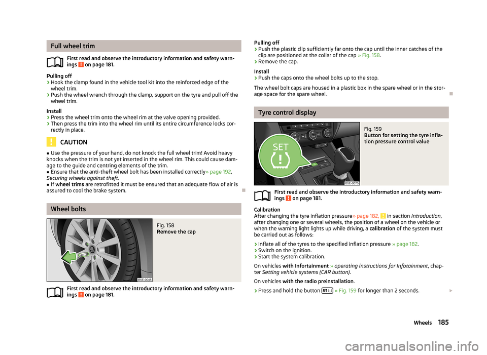
Fig. 158
Remove the cap
First read and observe the introductory information and safety warn- ings on page 181.
Pulling off›Push the plastic clip sufficiently far onto the cap until the inner catches of the
clip are positioned at the collar of the cap » Fig. 158.›
Remove the cap.
Install
›
Push the caps onto the wheel bolts up to the stop.
The wheel bolt caps are housed in a plastic box in the spare wheel or in the stor-
age space for the spare wheel.
Tyre control display
Fig. 159
Button for setting the tyre infla-
tion pressure control value
First read and observe the introductory information and safety warn-
ings on page 181.
Calibration
After changing the tyre inflation pressure » page 182, in section Introduction ,
after changing one or several wheels, the position of a wheel on the vehicle or
when the warning light lights up while driving, a calibration of the system must
be carried out as follows:
›
Inflate all of the tyres to the specified inflation pressure » page 182.
›
Switch on the ignition.
›
Start the system calibration.
On vehicles with Infortainment » operating instructions for Infotainment , chap-
ter Setting vehicle systems (CAR button) .
On vehicles with the radio preinstallation .
›
Press and hold the button
» Fig. 159 for longer than 2 seconds.
185Wheels
Page 188 of 222
While pressing the button, the warning light lights up. At the same time the
system memory is erased and the new calibration is started, which is confirmed
with an audible signal and then the warning light goes out.
If the warning light does not go out after the calibration, this indicates a sys-
tem fault. Seek help from a ŠKODA specialist garage.
The rolling circumference of the tyre can change if: › the tyre inflation pressure is too low;
› the structure of the tyre is damaged;
› the vehicle is loaded on one side;
› the wheels of an axle are loaded heavily (e.g. when towing a trailer or when
driving uphill or downhill);
› snow chains are mounted;
› the spare wheel is mounted;
› one wheel per axle was changed.WARNING■
When the warning light illuminates, immediately reduce the speed and
avoid sudden steering and brake manoeuvres. Stop the vehicle as soon as
possible and inspect the tyres and their inflation pressure.■
Under certain circumstances (e.g. sporty style of driving, wintry or unpaved
roads) the warning light can be delayed or does not light up at all.
Wheel bolts
First read and observe the introductory information and safety warn-ings
on page 181.
Wheels and wheel bolts are matched to each other in terms of design. Each time
you fit other wheels, e.g. light alloy wheels or wheels with winter tyres, you must
also use the matching wheel bolts of the correct length and shape of spherical cap. This is essential to ensure that the wheels are tightly fitted and that the
brake system operates properly.
Winter tyres
First read and observe the introductory information and safety warn-
ings
on page 181.
The handling of your vehicle will be significantly improved when driving on wintry roads if you fit winter tyres. Summer tyres on ice, snee and at temperatures be-
low 7 °C have less grip. This is especially true of low-profile tyres or high-speed
tyres .
To achieve the best possible handling properties, winter tyres must be fitted on
all 4 wheels, the minimum tread depth must be 4 mm and tyres must be no older than 4 years.
Winter tyres of a lower speed category can be used provided that the permissible
maximum speed of these tyres is not exceeded even if the possible maximum
speed of the vehicle is higher.
The winter tyres speed limit is set in the menu » operating instructions for Info-
tainment , chapter Setting vehicle systems (CAR button) .
For the sake of the environment
Fit the summer tyres on again in good time as they provide better handling prop-
erties, a shorter braking distance, less tyre noise, and reduced tyre wear on roadswhich are free of snow and ice as well as at temperatures above 7 °C. The fuelconsumption is also lower.
Snow chains
First read and observe the introductory information and safety warn-
ings
on page 181.
When driving on wintry roads, snow chains improve not only traction, but also the
braking performance.
Snow chains must only be mounted on the front wheels.
For technical reasons, it is only permissible to fit snow chains with the following wheel/tyre combinations.
Wheel sizeDepth (D)Tyre size6J x 15 a)43 mm195/65 R156J x 16 b)48 mm205/55 R166J x 17b)48 mm205/50 R17a)
Only fit snow chains with links and locks not larger than 13 mm.
b)
Only fit snow chains with links and locks not larger than 12 mm.
Remove the full wheel trims before installing the snow chains.
186General Maintenance
Page 191 of 222
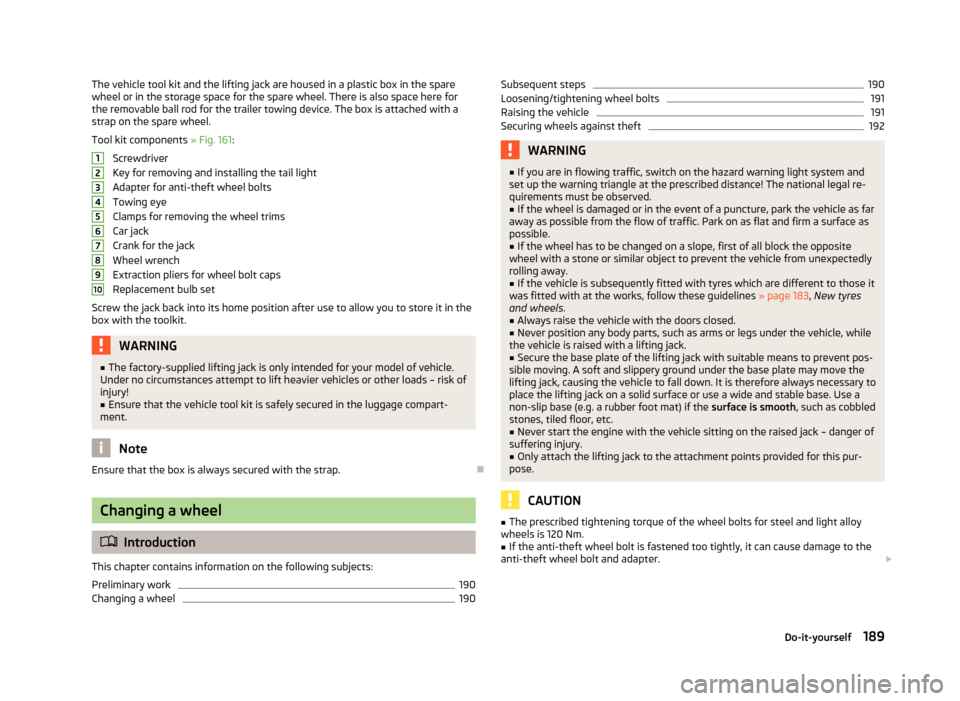
The vehicle tool kit and the lifting jack are housed in a plastic box in the sparewheel or in the storage space for the spare wheel. There is also space here for
the removable ball rod for the trailer towing device. The box is attached with a
strap on the spare wheel.
Tool kit components » Fig. 161:
Screwdriver
Key for removing and installing the tail light
Adapter for anti-theft wheel bolts
Towing eye
Clamps for removing the wheel trims
Car jack
Crank for the jack
Wheel wrench
Extraction pliers for wheel bolt caps
Replacement bulb set
Screw the jack back into its home position after use to allow you to store it in the
box with the toolkit.WARNING■ The factory-supplied lifting jack is only intended for your model of vehicle.
Under no circumstances attempt to lift heavier vehicles or other loads – risk of
injury!■
Ensure that the vehicle tool kit is safely secured in the luggage compart-
ment.
Note
Ensure that the box is always secured with the strap.
Changing a wheel
Introduction
This chapter contains information on the following subjects:
Preliminary work
190
Changing a wheel
19012345678910Subsequent steps190Loosening/tightening wheel bolts191
Raising the vehicle
191
Securing wheels against theft
192WARNING■ If you are in flowing traffic, switch on the hazard warning light system and
set up the warning triangle at the prescribed distance! The national legal re-
quirements must be observed.■
If the wheel is damaged or in the event of a puncture, park the vehicle as far
away as possible from the flow of traffic. Park on as flat and firm a surface as
possible.
■
If the wheel has to be changed on a slope, first of all block the opposite
wheel with a stone or similar object to prevent the vehicle from unexpectedly
rolling away.
■
If the vehicle is subsequently fitted with tyres which are different to those it
was fitted with at the works, follow these guidelines » page 183, New tyres
and wheels .
■
Always raise the vehicle with the doors closed.
■
Never position any body parts, such as arms or legs under the vehicle, while
the vehicle is raised with a lifting jack.
■
Secure the base plate of the lifting jack with suitable means to prevent pos-
sible moving. A soft and slippery ground under the base plate may move the
lifting jack, causing the vehicle to fall down. It is therefore always necessary to
place the lifting jack on a solid surface or use a wide and stable base. Use a
non-slip base (e.g. a rubber foot mat) if the surface is smooth, such as cobbled
stones, tiled floor, etc.
■
Never start the engine with the vehicle sitting on the raised jack – danger of
suffering injury.
■
Only attach the lifting jack to the attachment points provided for this pur-
pose.
CAUTION
■ The prescribed tightening torque of the wheel bolts for steel and light alloy
wheels is 120 Nm.■
If the anti-theft wheel bolt is fastened too tightly, it can cause damage to the
anti-theft wheel bolt and adapter.
189Do-it-yourself
Page 195 of 222

NoteImmediately replace the wheel that was repaired using the breakdown kit or con-
sult a ŠKODA specialist garage about repair possibilities.
Breakdown kit
Fig. 166
Components of the breakdown kit
First read and observe the introductory information and safety warn-
ings
on page 192.
The kit is located in a box under the floor covering in the luggage compartment.
Explanation of graphic Valve remover
Sticker with speed designation “max. 80 km/h”
Inflation hose with plug
Air compressor
Tyre inflation hose
Tyre inflation pressure indicator
Air release valve
ON and OFF switch
12 volt cable connector
Tyre inflator bottle with sealing agent
Replacement valve core
1234567891011The valve remover 1 has a slot at its lower end which fits into the valve core.
This is the only way in which you can remove and re-install the valve core from
the tyre valve. The same also applies to the replacement valve core 11
.
Note
■ Observe the manufacturer's usage instructions for the breakdown kit.■A new bottle of sealant can be purchased from ŠKODA Original Parts.
Preparing to use the breakdown kit
First read and observe the introductory information and safety warn-
ings
on page 192.
The following preparatory work must be carried out before using the breakdown
kit.
›
Park the vehicle as far away as possible from the flow of traffic. Park on as flat and firm a surface as possible.
›
If you are in flowing traffic, switch on the hazard warning light system and set
up the warning triangle at the prescribed distance! The national legal require-ments must be observed.
›
Let all of the occupants get out. While changing a tyre, the occupants of the
vehicle should not stand on the road (instead they should remain behind a crash
barrier).
›
Switch off the engine and move the gearshift lever into Neutral or move the se-
lector lever on the automatic gearbox into position P.
›
Firmly apply the handbrake.
›
Check that you can carry out the repairs with the breakdown kit » page 192.
›
If a trailer is connected, remove it.
›
Remove the breakdown kit from the luggage compartment.
›
Stick the sticker
2
» Fig. 166 on page 193 on the dash panel in view of the driv-
er.
›
Unscrew the valve cap.
›
Use the valve remover
1
to unscrew the valve core and place it on a clean sur-
face (rag, paper, etc.).
193Do-it-yourself
Page 201 of 222
Fuses and light bulbs
Fuses
Introduction
This chapter contains information on the following subjects:
Fuses in the dash panel
200
Fuses in the engine compartment
201
Individual electrical circuits are protected by fuses.
› Switch off the ignition and the appropriate consumer before changing a fuse.
› Find out which fuse belongs to the component that is not operat-
ing » page 200 , Fuses in the dash panel or » page 201 , Fuses in the engine
compartment .
› Take the plastic clip located under the cover of the fuse box in the engine com-
partment, insert into the fuse and remove it » Fig. 173 on page 201.
› A blown fuses is recognisable by the molten metal strip. Replace the faulty fuse
with a new one of the same amperage.
The plastic clip can be found underneath the cover of the fuse box in the engine
compartment » Fig. 173 on page 201.
Electrically adjustable seats are protected by automatic circuit breakers, which
switch on again automatically after a few seconds after the overload has been
eliminated.
Colour coding of fuses
ColourMaximum amperagelight brown5dark brown7.5red10blue15yellow/blue20white25green/pink30orange/green40red50WARNINGAlways read and observe the warnings before completing any work in the en-
gine compartment » page 169.
CAUTION
■
Have the electrical system checked as quickly as possible by a ŠKODA specialist
garage if a newly inserted fuse blows again after a short time.■
The cover for the fuse box in the engine compartment must always be applied
correctly. If the cover is not replaced properly, water may get into the fuse box -
risk of vehicle damage!
■
Never repair fuses and also do not replace them with a fuse of a higher amper-
age - risk of fire! A different electrical system could be damaged.
Note
■ We recommend always carrying replacement fuses in the vehicle. A box of re-
placement fuses can be purchased from ŠKODA Original Accessories.■
Multiple fuses may exist for a single power consuming device.
■
Multiple power consuming devices can share a single fuse.
199Fuses and light bulbs
Page 204 of 222
Fuse assignment in engine compartmentNo.Power consumerF1Control unit for ESCF2Control unit for ESC, ABSF3Engine control unitF4Engine control unit, relay for electric auxiliary heatingF5Engine componentsF6Brake sensor, engine componentsF7Coolant pump, engine componentsF8Lambda probeF9Ignition, control unit for glow plug system, engine componentsF10Control unit for fuel pump, ignitionF11Electrical auxiliary heating systemF12Electrical auxiliary heating systemF13Control unit for automatic gearboxF14Windscreen heater - leftF15HornF16IgnitionF17Control unit for ABS, ESC, engine control unitF18Data bus control unitF19Windscreen wipersF20AlarmF21ABSF22Engine control unitF23StarterF24Electrical auxiliary heating systemF31Not assignedF32Not assignedF33Not assignedF34Windscreen heater - rightF35Not assignedF36Not assignedNo.Power consumerF37Control unit for auxiliary heatingF38Not assigned
Bulbs
Introduction
This chapter contains information on the following subjects:
Headlights
203
Changing the bulb for the low beam
203
Replacing the bulb for main beam and separate daytime running lights
204
Changing the bulb for daytime running lights and parking light
204
Changing light bulbs for fog lights
204
Changing the bulb for the licence plate light
205
Tail lamp assembly
205
Replacing the bulbs in the tail lamp assembly
206
Some manual skills are required to change a bulb. For this reason, if uncertain, we recommend that bulbs are replaced by a ŠKODA specialist garage or other experthelp is sought.
› Switch off the ignition and all of the lights before replacing a bulb.
› Faulty bulbs must only be replaced with the same type of bulbs. The designa-
tion is located on the light socket or the glass bulb.
› A stowage compartment for replacement bulbs is located in a plastic box in the
spare wheel or underneath the floor covering in the luggage compartment.
WARNING■ Accidents can be caused if the road in front of the vehicle is not sufficiently
illuminated and the vehicle cannot or can only be seen with difficulty by other
road users.■
Always read and observe the warnings before completing any work in the
engine compartment » page 169.
202Do-it-yourself
Page 205 of 222
WARNING (Continued)■Bulbs H7 H8 and H15 are pressurised and may burst when changing the bulb
- risk of injury! We therefore recommended wearing gloves and safety glasses
when changing a bulb.■
Gas discharge bulbs (xenon bulbs) operate with a high voltage, professional
knowledge is required - danger to life!
CAUTION
■ Do not take hold of the glass bulb with naked fingers (even the smallest
amount of dirt reduces the working life of the light bulb). Use a clean cloth, nap-
kin, or similar.
Note
■ This Owner's Manual only describes the replacement of bulbs where it is possi-
ble to replace the bulbs on your own without any complications arising. Other light bulbs should be changed by a ŠKODA specialist garage.■
We recommend that a box of replacement bulbs be always carried in the vehi-
cle. Replacement bulbs can be purchased from ŠKODAOriginal Accessories.
■
We recommend that the headlight settings are checked by a ŠKODA specialist
garage after replacing a bulb in the main or low beam, or the fog lights.
■
Gas discharge bulbs and LED diodes are replaced by a ŠKODA specialist garage.
Headlights
Fig. 174
Bulb arrangement: Halogen headlights/Xenon headlights
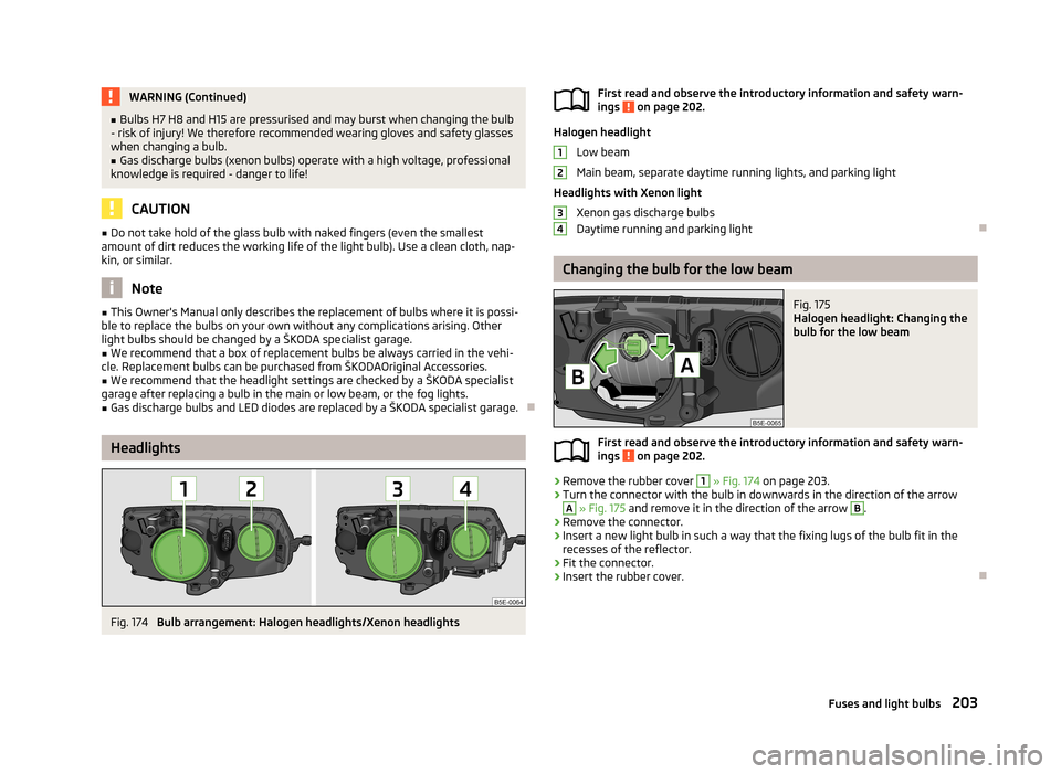
First read and observe the introductory information and safety warn- ings on page 202.
Halogen headlight
Low beam
Main beam, separate daytime running lights, and parking light
Headlights with Xenon light Xenon gas discharge bulbs
Daytime running and parking light
Changing the bulb for the low beam
Fig. 175
Halogen headlight: Changing the
bulb for the low beam
First read and observe the introductory information and safety warn- ings on page 202.
›
Remove the rubber cover
1
» Fig. 174 on page 203.
›
Turn the connector with the bulb in downwards in the direction of the arrow
A
» Fig. 175 and remove it in the direction of the arrow
B
.
›
Remove the connector.
›
Insert a new light bulb in such a way that the fixing lugs of the bulb fit in the
recesses of the reflector.
›
Fit the connector.
›
Insert the rubber cover.
1234203Fuses and light bulbs