SKODA OCTAVIA 2013 3.G / (5E) Owner's Manual
Manufacturer: SKODA, Model Year: 2013, Model line: OCTAVIA, Model: SKODA OCTAVIA 2013 3.G / (5E)Pages: 287, PDF Size: 18.55 MB
Page 101 of 287
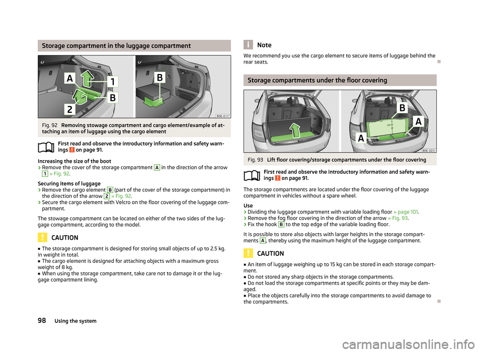
Storage compartment in the luggage compartmentFig. 92
Removing stowage compartment and cargo element/example of at-
taching an item of luggage using the cargo element
First read and observe the introductory information and safety warn-ings
on page 91.
Increasing the size of the boot
›
Remove the cover of the storage compartment
A
in the direction of the arrow
1
» Fig. 92 .
Securing items of luggage
›
Remove the cargo element
B
(part of the cover of the storage compartment) in
the direction of the arrow
2
» Fig. 92 .
›
Secure the cargo element with Velcro on the floor covering of the luggage com-
partment.
The stowage compartment can be located on either of the two sides of the lug-
gage compartment, according to the model.
CAUTION
■ The storage compartment is designed for storing small objects of up to 2.5 kg.
in weight in total.■
The cargo element is designed for attaching objects with a maximum gross
weight of 8 kg.
■
When using the storage compartment, take care not to damage it or the lug-
gage compartment lining.
NoteWe recommend you use the cargo element to secure items of luggage behind the
rear seats.
Storage compartments under the floor covering
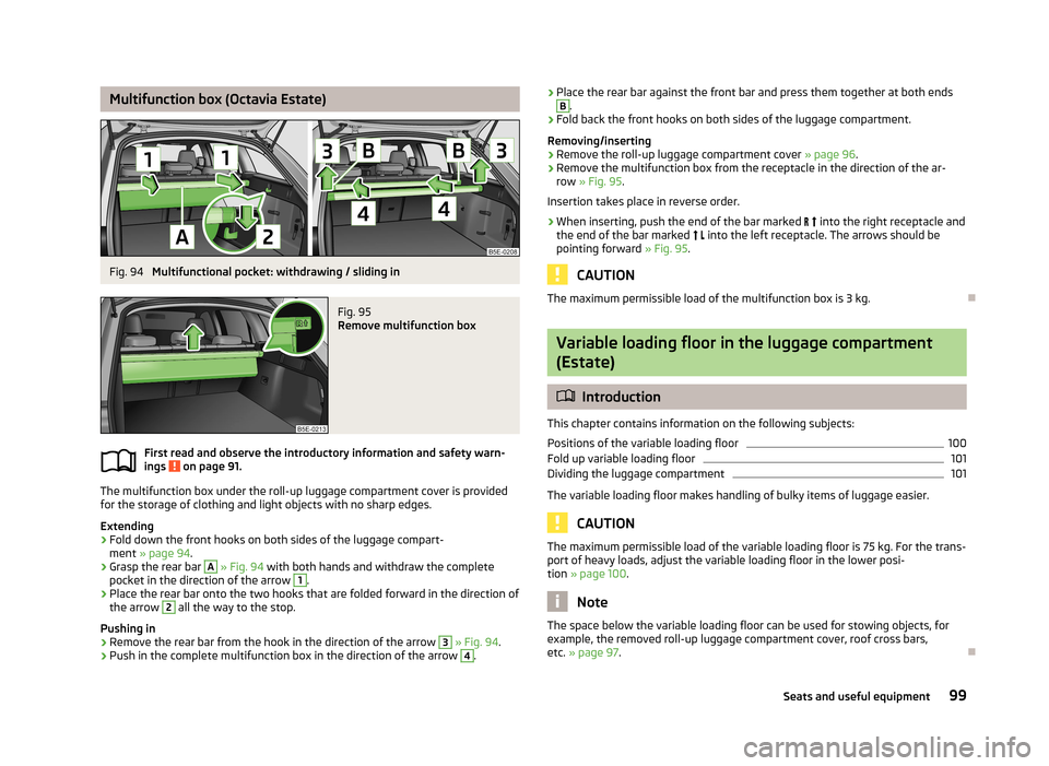
Fig. 93
Lift floor covering/storage compartments under the floor covering
First read and observe the introductory information and safety warn-
ings
on page 91.
The storage compartments are located under the floor covering of the luggage compartment in vehicles without a spare wheel.
Use
›
Dividing the luggage compartment with variable loading floor » page 101.
›
Remove the fog floor covering in the direction of the arrow » Fig. 93.
›
Fix the hook
B
to the top edge of the variable loading floor.
It is possible to store also objects with larger heights in the storage compart- ments
A
, thereby using the maximum height of the luggage compartment.
CAUTION
■ An item of luggage weighing up to 15 kg can be stored in each storage compart-
ment.■
Do not stored any sharp objects in the storage compartments.
■
Do not load the storage compartments at specific points or they may be dam-
aged.
■
Place the objects carefully into the storage compartments to avoid damage to
the compartments.
98Using the system
Page 102 of 287
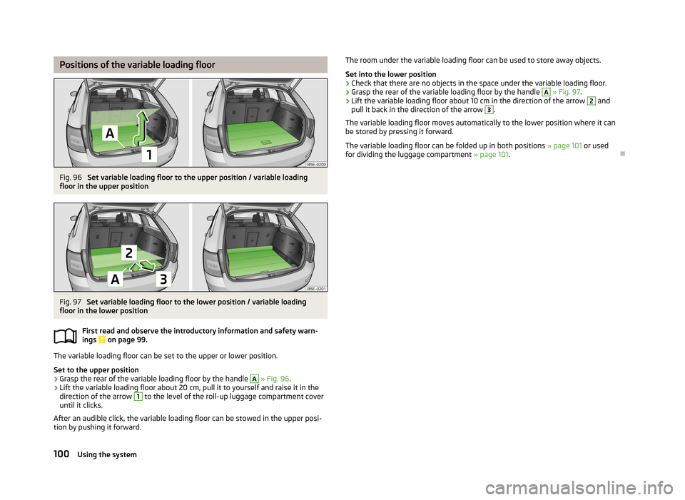
Multifunction box (Octavia Estate)Fig. 94
Multifunctional pocket: withdrawing / sliding in
Fig. 95
Remove multifunction box
First read and observe the introductory information and safety warn-
ings on page 91.
The multifunction box under the roll-up luggage compartment cover is provided
for the storage of clothing and light objects with no sharp edges.
Extending
›
Fold down the front hooks on both sides of the luggage compart- ment » page 94 .
›
Grasp the rear bar
A
» Fig. 94 with both hands and withdraw the complete
pocket in the direction of the arrow
1
.
›
Place the rear bar onto the two hooks that are folded forward in the direction of
the arrow
2
all the way to the stop.
Pushing in
›
Remove the rear bar from the hook in the direction of the arrow
3
» Fig. 94 .
›
Push in the complete multifunction box in the direction of the arrow
4
.
›Place the rear bar against the front bar and press them together at both endsB.›
Fold back the front hooks on both sides of the luggage compartment.
Removing/inserting
›
Remove the roll-up luggage compartment cover » page 96.
›
Remove the multifunction box from the receptacle in the direction of the ar-
row » Fig. 95 .
Insertion takes place in reverse order.
›
When inserting, push the end of the bar marked into the right receptacle and
the end of the bar marked into the left receptacle. The arrows should be
pointing forward » Fig. 95.
CAUTION
The maximum permissible load of the multifunction box is 3 kg.
Variable loading floor in the luggage compartment
(Estate)
Introduction
This chapter contains information on the following subjects:
Positions of the variable loading floor
100
Fold up variable loading floor
101
Dividing the luggage compartment
101
The variable loading floor makes handling of bulky items of luggage easier.
CAUTION
The maximum permissible load of the variable loading floor is 75 kg. For the trans- port of heavy loads, adjust the variable loading floor in the lower posi-
tion » page 100 .
Note
The space below the variable loading floor can be used for stowing objects, for
example, the removed roll-up luggage compartment cover, roof cross bars,
etc. » page 97 .
99Seats and useful equipment
Page 103 of 287
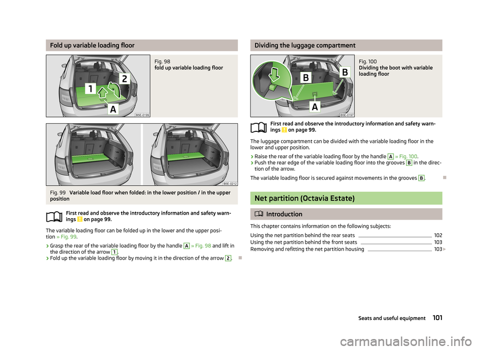
Positions of the variable loading floorFig. 96
Set variable loading floor to the upper position / variable loading
floor in the upper position
Fig. 97
Set variable loading floor to the lower position / variable loading
floor in the lower position
First read and observe the introductory information and safety warn-ings
on page 99.
The variable loading floor can be set to the upper or lower position.
Set to the upper position
›
Grasp the rear of the variable loading floor by the handle
A
» Fig. 96 .
›
Lift the variable loading floor about 20 cm, pull it to yourself and raise it in the
direction of the arrow
1
to the level of the roll-up luggage compartment cover
until it clicks.
After an audible click, the variable loading floor can be stowed in the upper posi-
tion by pushing it forward.
The room under the variable loading floor can be used to store away objects.
Set into the lower position›
Check that there are no objects in the space under the variable loading floor.
›
Grasp the rear of the variable loading floor by the handle
A
» Fig. 97 .
›
Lift the variable loading floor about 10 cm in the direction of the arrow
2
and
pull it back in the direction of the arrow
3
.
The variable loading floor moves automatically to the lower position where it can
be stored by pressing it forward.
The variable loading floor can be folded up in both positions » page 101 or used
for dividing the luggage compartment » page 101.
100Using the system
Page 104 of 287
Fold up variable loading floorFig. 98
fold up variable loading floor
Fig. 99
Variable load floor when folded: in the lower position / in the upper
position
First read and observe the introductory information and safety warn-
ings
on page 99.
The variable loading floor can be folded up in the lower and the upper posi-
tion » Fig. 99 .
›
Grasp the rear of the variable loading floor by the handle
A
» Fig. 98 and lift in
the direction of the arrow
1
.
›
Fold up the variable loading floor by moving it in the direction of the arrow
2
.
Dividing the luggage compartmentFig. 100
Dividing the boot with variable
loading floor
First read and observe the introductory information and safety warn-
ings on page 99.
The luggage compartment can be divided with the variable loading floor in the
lower and upper position.
›
Raise the rear of the variable loading floor by the handle
A
» Fig. 100 .
›
Push the rear edge of the variable loading floor into the grooves
B
in the direc-
tion of the arrow.
The variable loading floor is secured against movements in the grooves
B
.
Net partition (Octavia Estate)
Introduction
This chapter contains information on the following subjects: Using the net partition behind the rear seats
102
Using the net partition behind the front seats
103
Removing and refitting the net partition housing
103
101Seats and useful equipment
Page 105 of 287
WARNING■Check that the crossbar of the net partition is hung firmly into the recepta-
cles D » Fig. 101 on page 102 and C » Fig. 103 on page 103.■
The belts and the belt locks must be in their original position after folding
back the seat backrests – they must be ready to use.
■
The seat backrests must be securely locked in position so that no objects in
the luggage compartment can slide into the passenger compartment on sud-
den braking – risk of injury.
■
Ensure that the rear seat backrests are properly engaged. Only then can the
seat belt for the middle seat reliably fulfil its function.
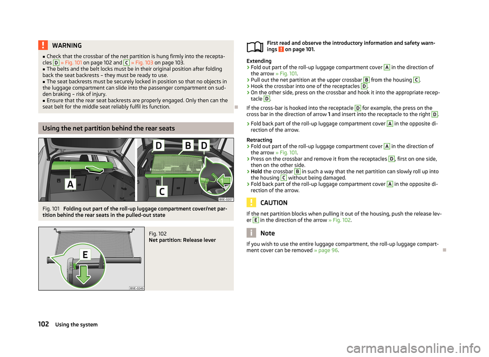
Using the net partition behind the rear seats
Fig. 101
Folding out part of the roll-up luggage compartment cover/net par-
tition behind the rear seats in the pulled-out state
Fig. 102
Net partition: Release lever
First read and observe the introductory information and safety warn-
ings on page 101.
Extending
›
Fold out part of the roll-up luggage compartment cover
A
in the direction of
the arrow » Fig. 101.
›
Pull out the net partition at the upper crossbar
B
from the housing
C
.
›
Hook the crossbar into one of the receptacles
D
.
›
On the other side, press on the crossbar and hook it into the appropriate recep-
tacle
D
.
If the cross-bar is hooked into the receptacle
D
for example, the press on the
cross bar in the direction of arrow 1 and insert into the receptacle to the right
D
.
›
Fold back part of the roll-up luggage compartment cover
A
in the opposite di-
rection of the arrow.
Retracting
›
Fold out part of the roll-up luggage compartment cover
A
in the direction of
the arrow » Fig. 101.
›
Press on the crossbar and remove it from the receptacles
D
, first on one side,
then on the other side.
›
Hold the crossbar
B
in such a way that the net partition can slowly roll up into
the housing
C
without being damaged.
›
Fold back part of the roll-up luggage compartment cover
A
in the opposite di-
rection of the arrow.
CAUTION
If the net partition blocks when pulling it out of the housing, push the release lev- er E in the direction of the arrow » Fig. 102.
Note
If you wish to use the entire luggage compartment, the roll-up luggage compart-
ment cover can be removed » page 96.
102Using the system
Page 106 of 287
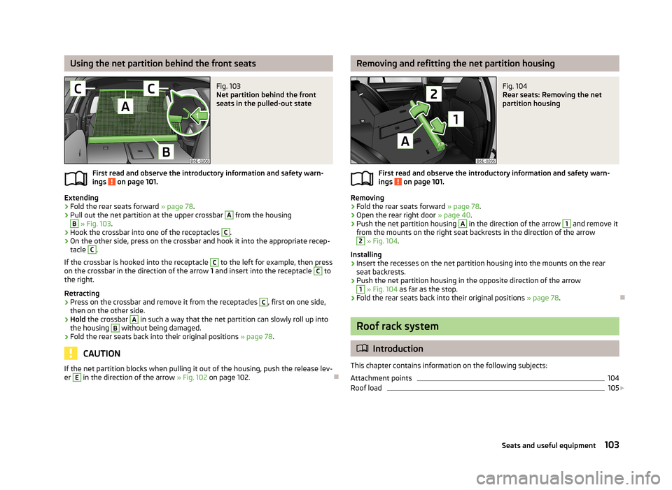
Using the net partition behind the front seatsFig. 103
Net partition behind the front
seats in the pulled-out state
First read and observe the introductory information and safety warn-
ings on page 101.
Extending
›
Fold the rear seats forward » page 78.
›
Pull out the net partition at the upper crossbar
A
from the housing
B
» Fig. 103 .
›
Hook the crossbar into one of the receptacles
C
.
›
On the other side, press on the crossbar and hook it into the appropriate recep-
tacle
C
.
If the crossbar is hooked into the receptacle
C
to the left for example, then press
on the crossbar in the direction of the arrow 1 and insert into the receptacle
C
to
the right.
Retracting
›
Press on the crossbar and remove it from the receptacles
C
, first on one side,
then on the other side.
›
Hold the crossbar
A
in such a way that the net partition can slowly roll up into
the housing
B
without being damaged.
›
Fold the rear seats back into their original positions » page 78.
CAUTION
If the net partition blocks when pulling it out of the housing, push the release lev-
er E in the direction of the arrow » Fig. 102 on page 102.
Removing and refitting the net partition housingFig. 104
Rear seats: Removing the net
partition housing
First read and observe the introductory information and safety warn-
ings on page 101.
Removing
›
Fold the rear seats forward » page 78.
›
Open the rear right door » page 40.
›
Push the net partition housing
A
in the direction of the arrow
1
and remove it
from the mounts on the right seat backrests in the direction of the arrow
2
» Fig. 104 .
Installing
›
Insert the recesses on the net partition housing into the mounts on the rear seat backrests.
›
Push the net partition housing in the opposite direction of the arrow
1
» Fig. 104 as far as the stop.
›
Fold the rear seats back into their original positions » page 78.
Roof rack system
Introduction
This chapter contains information on the following subjects:
Attachment points
104
Roof load
105
103Seats and useful equipment
Page 107 of 287
WARNING■The items which you transport on the roof rack must be reliably attached –
risk of accident!■
Always secure the load with appropriate and undamaged lashing straps or
tensioning straps.
■
Distribute the load evenly over the roof rack system.
■
When transporting heavy objects or objects which take up a large area on
the roof rack system, the handling of the car may change as a result of the displacement of the centre of gravity. The style of driving and speed musttherefore be adapted to the current circumstances.
■
Avoid abrupt and sudden driving/braking manoeuvres.
■
Adjust the speed and driving style to the visibility, weather, road and traffic
conditions.
■
The permissible roof load, permissible axle loads and gross permissible
weight of the vehicle must not be exceeded under any circumstances – risk of
accident!
CAUTION
■ Only use roof rack systems approved by ŠKODA AUTO a.s.■When dealing with roof rack systems, the installation instructions supplied with
the roof luggage rack system must be observed.■
On models fitted with a sliding/tilting roof, ensure that the sliding/tilting roof
does not strike any items of luggage transported on the roof.
■
Ensure that the luggage compartment lid does not hit the roof load when
opened.
■
The height of the vehicle changes after mounting a roof luggage rack system
and the load that is secured to it. Compare the vehicle height with available clear-
ances, such as underpasses and garage doors.
■
Always remove the roof luggage rack system before entering an automated car
wash.
■
Ensure the roof aerial is not impaired by the secured load.
For the sake of the environment
The increased aerodynamic drag results in a higher fuel consumption.NoteThe removed roof rack for the Octavia Estate can be stowed in the stowage com-
partment under the variable loading floor » page 97, Stowing roll-up luggage
compartment cover and roof racks .
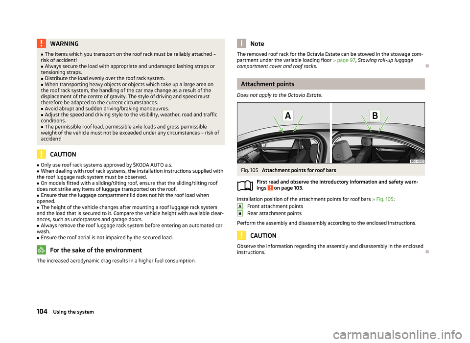
Attachment points
Does not apply to the Octavia Estate.
Fig. 105
Attachment points for roof bars
First read and observe the introductory information and safety warn- ings
on page 103.
Installation position of the attachment points for roof bars » Fig. 105:
Front attachment points
Rear attachment points
Perform the assembly and disassembly according to the enclosed instructions.
CAUTION
Observe the information regarding the assembly and disassembly in the enclosed
instructions.
AB104Using the system
Page 108 of 287
Roof loadFirst read and observe the introductory information and safety warn-
ings
on page 103.
The maximum permissible roof load (including roof rack system) of 75 kg and the
maximum permissible total weight of the vehicle should not be exceeded.
The full permissible roof load cannot be used if a roof rack system with a lower
load carrying capacity is used. In this case, the roof rack system must only be loa-
ded up to the maximum weight limit specified in the fitting instructions.
105Seats and useful equipment
Page 109 of 287
Heating and air-conditioning
Heating, ventilation, cooling
Introduction
This chapter contains information on the following subjects:
Air outlets
107
Using the cooling system economically
107
Operational problems
108
The heating effect is dependent upon the coolant temperature, thus full heat
output only occurs when the engine has reached its operating temperature.
If the cooling system is switched on, the temperature and air humidity drops in
the vehicle. The cooling system prevents the windows from misting up during the
cold season of the year.
It is possible to briefly activate recirculated air mode to enhance the cooling ef-
fect.
Please refer to the information regarding recirculated air mode for the air-condi-
tioning system » page 111 or for Climatronic » page 114.
WARNINGFor your own safety and that of other road users, ensure that all the windows
are free of ice, snow and misting. Please familiarize yourself about how to cor-
rectly operate the heating and ventilation systems, how to demist and defrost
the windows, as well as with the cooling mode.
CAUTION
■ The air inlet in front of the windscreen must be free of e.g. ice, snow or leaves
to ensure that the heating and cooling system operates properly.■
After switching on the cooling Condensation from the evaporator of the air con-
ditioning may drip down and form a puddle below the vehicle. This is not a leak!
Note■ The used air streams out through the vents in the luggage compartment.■We recommend that you do not smoke in the vehicle when the recirculating air
mode is operating since the smoke which is drawn at the evaporator from the in-
terior of the vehicle forms deposits in the evaporator of the air conditioning sys- tem. This produces a permanent odour when the air conditioning system is oper-ating which can only be eliminated through considerable effort and expense (re-
placement of compressor).
106Using the system
Page 110 of 287
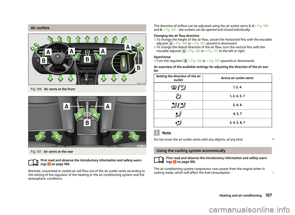
Air outletsFig. 106
Air vents at the front
Fig. 107
Air vents at the rear
First read and observe the introductory information and safety warn-
ings
on page 106.
Warmed, unwarmed or cooled air will flow out of the air outlet vents according to
the setting of the regulator of the heating or the air conditioning system and the atmospheric conditions.
The direction of airflow can be adjusted using the air outlet vents 3, 4 » Fig. 106
and 6 » Fig. 107 - the outlets can be opened and closed individually.
Changing the air flow direction›
To change the height of the air flow, swivel the horizontal fins with the movable
adjuster
A
» Fig. 106 or » Fig. 107 upward or downward.
›
To change the lateral direction of the air flow, turn the vertical fins with the
movable adjuster
A
» Fig. 106 or » Fig. 107 to the left or right.
Open/close
›
Turn the regulator
B
» Fig. 106 or » Fig. 107 upwards or downwards.
An overview of the available settings for adjusting the direction of the air out- let.
Setting the direction of the air
outletActive air outlet vents1, 2, 41, 2, 4, 5, 7 3, 4, 64, 5, 73, 4, 5, 6, 7
Note
Do not cover the air outlet vents with any objects, of any kind.
Using the cooling system economically
First read and observe the introductory information and safety warn-
ings
on page 106.
The air conditioning system compressor uses power from the engine when in
cooling mode, which will affect the fuel consumption.
107Heating and air-conditioning