SKODA OCTAVIA 2014 3.G / (5E) Owner's Manual
Manufacturer: SKODA, Model Year: 2014, Model line: OCTAVIA, Model: SKODA OCTAVIA 2014 3.G / (5E)Pages: 280, PDF Size: 35.53 MB
Page 101 of 280
WARNINGNever place flammable objects in the ashtray – risk of fire!
CAUTION
When removing, do not hold the ashtray on the cover – risk of breakage.
12-Volt power outlet
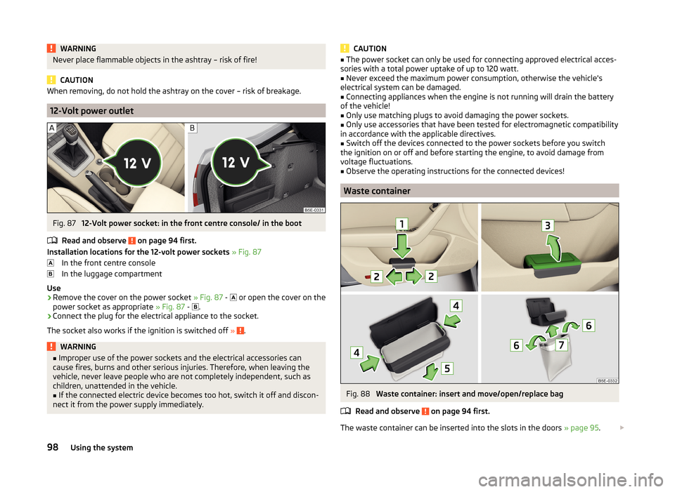
Fig. 87
12-Volt power socket: in the front centre console/ in the boot
Read and observe
on page 94 first.
Installation locations for the 12-volt power sockets » Fig. 87
In the front centre console
In the luggage compartment
Use
›
Remove the cover on the power socket » Fig. 87 -
or open the cover on the
power socket as appropriate » Fig. 87 -
.
›
Connect the plug for the electrical appliance to the socket.
The socket also works if the ignition is switched off »
.
WARNING■
Improper use of the power sockets and the electrical accessories can
cause fires, burns and other serious injuries. Therefore, when leaving the
vehicle, never leave people who are not completely independent, such as
children, unattended in the vehicle.■
If the connected electric device becomes too hot, switch it off and discon-
nect it from the power supply immediately.
CAUTION■ The power socket can only be used for connecting approved electrical acces-
sories with a total power uptake of up to 120 watt.■
Never exceed the maximum power consumption, otherwise the vehicle's
electrical system can be damaged.
■
Connecting appliances when the engine is not running will drain the battery
of the vehicle!
■
Only use matching plugs to avoid damaging the power sockets.
■
Only use accessories that have been tested for electromagnetic compatibility
in accordance with the applicable directives.
■
Switch off the devices connected to the power sockets before you switch
the ignition on or off and before starting the engine, to avoid damage from
voltage fluctuations.
■
Observe the operating instructions for the connected devices!
Waste container
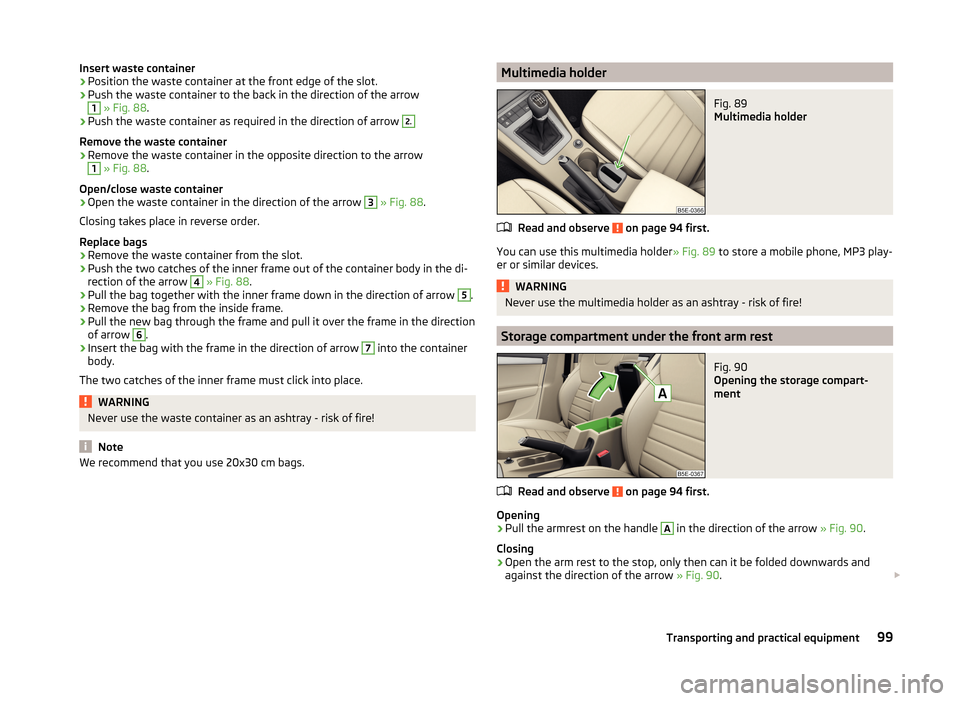
Fig. 88
Waste container: insert and move/open/replace bag
Read and observe
on page 94 first.
The waste container can be inserted into the slots in the doors » page 95.
98Using the system
Page 102 of 280
Insert waste container›Position the waste container at the front edge of the slot.›
Push the waste container to the back in the direction of the arrow
1
» Fig. 88 .
›
Push the waste container as required in the direction of arrow
2.
Remove the waste container
›
Remove the waste container in the opposite direction to the arrow
1
» Fig. 88 .
Open/close waste container
›
Open the waste container in the direction of the arrow
3
» Fig. 88 .
Closing takes place in reverse order.
Replace bags
›
Remove the waste container from the slot.
›
Push the two catches of the inner frame out of the container body in the di-
rection of the arrow
4
» Fig. 88 .
›
Pull the bag together with the inner frame down in the direction of arrow
5
.
›
Remove the bag from the inside frame.
›
Pull the new bag through the frame and pull it over the frame in the direction
of arrow
6
.
›
Insert the bag with the frame in the direction of arrow
7
into the container
body.
The two catches of the inner frame must click into place.
WARNINGNever use the waste container as an ashtray - risk of fire!
Note
We recommend that you use 20x30 cm bags.Multimedia holderFig. 89
Multimedia holder
Read and observe on page 94 first.
You can use this multimedia holder » Fig. 89 to store a mobile phone, MP3 play-
er or similar devices.
WARNINGNever use the multimedia holder as an ashtray - risk of fire!
Storage compartment under the front arm rest
Fig. 90
Opening the storage compart-
ment
Read and observe on page 94 first.
Opening
›
Pull the armrest on the handle
A
in the direction of the arrow » Fig. 90.
Closing
›
Open the arm rest to the stop, only then can it be folded downwards and
against the direction of the arrow » Fig. 90.
99Transporting and practical equipment
Page 103 of 280
WARNINGFor safety reasons, the storage compartment should not be opened to an
end stop while driving.
Glasses compartment
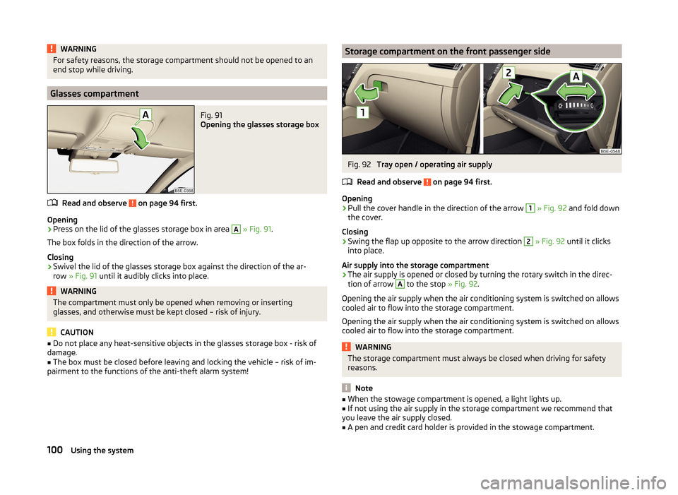
Fig. 91
Opening the glasses storage box
Read and observe on page 94 first.
Opening
›
Press on the lid of the glasses storage box in area
A
» Fig. 91 .
The box folds in the direction of the arrow.
Closing
›
Swivel the lid of the glasses storage box against the direction of the ar-
row » Fig. 91 until it audibly clicks into place.
WARNINGThe compartment must only be opened when removing or inserting
glasses, and otherwise must be kept closed – risk of injury.
CAUTION
■ Do not place any heat-sensitive objects in the glasses storage box - risk of
damage.■
The box must be closed before leaving and locking the vehicle – risk of im-
pairment to the functions of the anti-theft alarm system!
Storage compartment on the front passenger sideFig. 92
Tray open / operating air supply
Read and observe
on page 94 first.
Opening
›
Pull the cover handle in the direction of the arrow
1
» Fig. 92 and fold down
the cover.
Closing
›
Swing the flap up opposite to the arrow direction
2
» Fig. 92 until it clicks
into place.
Air supply into the storage compartment
›
The air supply is opened or closed by turning the rotary switch in the direc-
tion of arrow
A
to the stop » Fig. 92.
Opening the air supply when the air conditioning system is switched on allows cooled air to flow into the storage compartment.
Opening the air supply when the air conditioning system is switched on allows
cooled air to flow into the storage compartment.
WARNINGThe storage compartment must always be closed when driving for safety
reasons.
Note
■ When the stowage compartment is opened, a light lights up.■If not using the air supply in the storage compartment we recommend that
you leave the air supply closed.■
A pen and credit card holder is provided in the stowage compartment.
100Using the system
Page 104 of 280
Clothes hookRead and observe
on page 94 first.
The clothes hooks are located on the middle door pillars of the vehicle and on
the handle of the headliner above each of the rear doors.
WARNING■ Only hang light items of clothing on the hooks. Never leave any heavy or
sharp-edged objects in the pockets of the items of clothing.■
Do not use clothes hangers for hanging up items of clothing otherwise
this may reduce the effectiveness of head airbags.
■
Ensure that any clothes hanging from the hooks do not impair your vision
to the rear.
CAUTION
The maximum permissible load of the hooks is 2 kg.
Storage pockets on the front seats
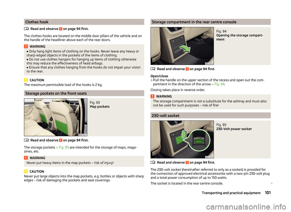
Fig. 93
Map pockets
Read and observe on page 94 first.
The storage pockets » Fig. 93 are intended for the storage of maps, maga-
zines, etc.
WARNINGNever put heavy items in the map pockets – risk of injury!
CAUTION
Never put large objects into the map pockets, e.g. bottles or objects with sharp
edges - risk of damaging the pockets and seat coverings.Storage compartment in the rear centre consoleFig. 94
Opening the storage compart-
ment
Read and observe on page 94 first.
Open/close
›
Pull the handle on the upper section of the recess and open out the com-
partment in the direction of the arrow » Fig. 94.
Closing takes place in reverse order.
WARNINGThe storage compartment is not a substitute for the ashtray and must also
not be used for such purposes – risk of fire!
230-volt socket
Fig. 95
230-Volt power socket
Read and observe on page 94 first.
The 230-volt socket (hereinafter referred to only as a socket) is provided for
the connection of approved electrical accessories with a two-pin 230-volt plug
and a total power consumption of up to 150 watts.
The socket is located in the rear centre console.
101Transporting and practical equipment
Page 105 of 280
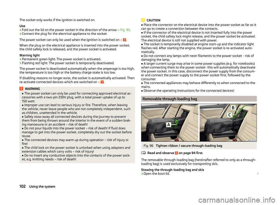
The socket only works if the ignition is switched on.
Use›
Fold out the lid on the power socket in the direction of the arrow » Fig. 95.
›
Connect the plug for the electrical appliance to the socket.
The power socket can only be used when the ignition is switched on »
.
When the plug on the electrical appliance is inserted into the power socket,
the child safety lock is released, and the power socket is activated.
Warning light
› Permanent green light: The power socket is activated.
› Flashing red light: The power socket is temporarily deactivated.
The power socket is deactivated automatically when the amperage is too high,
the temperature is too high or the battery charge state is too low.
If disabling reasons no longer exist, the socket is automatically activated. Then
re-activate connected devices which are switched on »
.
WARNING■
The power socket can only be used for connecting approved electrical ac-
cessories with a two-pin 230V plug, with a total power uptake of up to
150 watt.■
Improper use can lead to serious injury or fire. Therefore, when leaving
the vehicle, never leave people who are not completely independent, such
as children, unattended in the vehicle.
■
Safely stow away all connected devices during the journey to prevent
them from being thrown around the interior in the event of a sudden brak-
ing manoeuvre or an accident – risk of death!
■
Do not pour liquids into the power socket – risk of death! If fluid does
manage to get into the power socket, completely dry out the socket before
reuse.
■
The connected devices may warm up during operation – risk of injury or
fire!
■
The child lock on the power socket is unlocked when using adapters and
extension cables which carry volts – risk of injury!
■
Do no insert any conductive objects into the contacts of the power sock-
et, e.g. knitting needs – risk of death!
CAUTION■ Place the connector on the electrical device into the power socket as far as it
can go to create a connection between the contacts.■
If the connector of the electrical device is not inserted fully into the power
socket, the child safety lock might release, and the power socket be activated.
The electrical device is still not supplied with power.
■
The socket is temporarily disabled at engine start-up and the indicator light
flashes red. After starting the engine, the power socket is re-activated auto-
matically.
■
Do not connect any lamps with neon filaments to the power socket - risk of
damaging the lamp.
■
A larger current surge may arise in some power supplies (e.g. for notebooks)
when connecting them to the power socket- this will automatically deactivate
the power socket. In this case, disconnect the power supply from the consum-
er and connect the power supply to the power socket first, followed by the
consumer.
■
The connected appliances may behave differently to when connected to the
mains.
■
Observe the operating instructions for the connected devices!
Removable through-loading bag
Fig. 96
Tighten ribbon / secure through-loading bag
Read and observe
on page 94 first.
The removable through-loading bag (hereinafter referred to only as a through-
loading bag) is used exclusively for transporting skis.
Stowing the through-loading bag and skis
›
Open the boot lid.
102Using the system
Page 106 of 280

›Fold the rear armrest and the cover in the seat backrest down-
wards » page 94 .›
Place the empty, through-loading bag in such a way that the end of the bag
with the zip is in the boot.
›
Push the skis into the through-loading bag from the boot » .
›
Close the through-loading bag.
Securing the through-loading bag and skis
›
Tighten the strap
A
on the free end around the skis in front of the bind-
ings » Fig. 96 .
›
Fold the seat backrest a little forward.
›
Guide the securing strap
B
through the opening in the seat backrest around
the upper part of the seat backrest.
›
Then push the seat backrest back into the upright position until the unlock-
ing button clicks into place - check by pulling on the seat backrest.
›
Insert the securing strap
B
into the lock
C
until it clicks into place.
WARNING■ After placing skis into the through-loading bag, you must secure the bag
with the securing strap B » Fig. 96 .■
The strap
A
must hold the skis tight.
■
Make sure that the strap
A
holds all skis in front of the binding (see also
the text on the through-loading bag).
■
The total weight of the skis which are transported must not exceed
24 kg.
CAUTION
■ Never fold and stow the through-loading bag when it is wet - risk of damag-
ing the through-loading bag.■
The through-loading bag is designed for the transportation of up to four
pairs of skis.
■
Place the skis with the tips facing to the front and the sticks with the tips
facing to the rear. into the through-loading bag.
Luggage compartment
Introduction
This chapter contains information on the following subjects:
Fastening elements
104
Fixing nets
105Folding double hooks105Foldable hook106
Floor covering
106
Floor covering on both sides
106
Luggage net
106
Luggage compartment cover
107
Retractable luggage compartment cover
108
Storage compartment with cargo element
108
Storage compartments under the floor covering
109
Multi-function pocket
110
Class N1 vehicles
110
Please observe the following for the purpose of maintaining good handling
characteristics of your vehicle:
›
Distribute loads as evenly as possible.
›
Place heavy objects as far forward as possible.
›
Attach the items of luggage to the lashing eyes or by using the fixing
nets » page 104 .
In the event of an accident, even small and light objects gain so much kinetic
energy that they can cause severe injuries.
The magnitude of the kinetic energy is dependent on the speed at which the
vehicle is travelling and the weight of the object.
Example: In the event of a frontal collision at a speed of 50 km/h, an object
with a weight of 4.5 kg produces an energy, which corresponds to 20 times its
own weight. This means that it results in a weight of approx. 90 kg “ ”.
Luggage compartment light
The warning light turns on when tailgate is opened.
The warning light turns off when the tailgate is closed.
If the boot lid is open and the ignition switched off, the light will extinguish
automatically after around 10 minutes.
WARNING■ Always store transported objects in the boot and attach them to the lash-
ing eyes.■
Loose objects can be thrown forward during a sudden manoeuvre or in
case of an accident and can injure the occupants or other road users.
103Transporting and practical equipment
Page 107 of 280

WARNING (Continued)■Loose objects could hit a deployed airbag and injure occupants – danger
of death!■
Please note that the handling properties of the vehicle may be affected
when transporting heavy objects as the centre of gravity can be displaced –
risk of accident! The speed and style of driving must be adjusted according-
ly.
■
If the items of luggage or objects are attached to the lashing eyes with
unsuitable or damaged lashing straps, injuries can occur in the event of
braking manoeuvres or accidents. To prevent items of luggage from moving
around, always use suitable lashing straps which must be firmly attached
to the lashing eyes.
■
The items carried in the luggage compartment must be stored in such a
way that no objects are able to slip forward if any sudden driving or braking
manoeuvres are undertaken – risk of injury!
■
When transporting objects in the luggage compartment that has been en-
larged by folding the rear seats forward, ensure the safety of the passen-
gers transported on the other rear seats » page 11, Correct seated position
for the passengers in the rear seats .
■
Do not drive with the luggage compartment lid fully opened or slightly
ajar otherwise exhaust gases may get into the interior of the vehicle – risk
of poisoning!
■
Do not exceed the permissible axle loads and permissible gross weight of
the vehicle – risk of accident!
■
Do not transport people in the boot!
CAUTION
■ Make sure that transported objects with sharp edges do not damage the
threads of the following devices. ■Rear window heater.
■ Rear window with an integrated antenna.
■ Integrated antenna in the rear side windows.■
The tyre pressure must be adjusted to the load » page 204.
Fastening elementsFig. 97
Fastening elements: Variant 1/variant 2 (G-TEC)
Fig. 98
Fastening elements: Variant 3/variant 4
Read and observe
and on page 103 first.
Overview of the fastening elements » Fig. 97 and » Fig. 98
Fastening elements only for fastening fixing nets
Fastening elements only for fastening fixing nets
Lashing eyelets for fastening items of luggage and fixing nets
Lashing eyelets for fastening items of luggage and fixing nets
Lashing eyelets for fastening items of luggage and fixing nets
The lashing eyelet
B
is located behind the folding rear seat backrest .
ABCDE104Using the system
Page 108 of 280

CAUTION■The maximum permissible static load of the individual lashing eyes C and Eis 3.5 kN (350 kg).■
The maximum permissible static load of the individual lashing eyes
D
is 1.5
kN (150 kg).
Fixing nets
Fig. 99
Fastening examples for nets
Fig. 100
Fastening example for vertical
pockets
Read and observe and on page 103 first.
Fastening examples for nets » Fig. 99
Horizontal pocket
Floor net
Vertical pocket
If the vehicle is equipped with the variable loading floor and this is in the upper
position, then the lashing eyes
E
» Fig. 98 on page 104 can be used for attach-
ing the nets.
ABCWARNINGDo not exceed the maximum permissible load of the fixing nets. Heavy ob-
jects are not secured sufficiently – risk of injury!
CAUTION
■ The maximum permissible load of the fixing nets is 1.5 kg.■Do not place any sharp objects in the nets – risk of damaging the net.■
For vehicles with lashing eyes
D
» Fig. 97 on page 104 , only the following
nets can be attached. ■ Horizontal pocket behind the seats.
■ Floor net, which can be attached to the rear fastening elements
A
» Fig. 97
on page 104 in the rear area.
Folding double hooks
Fig. 101
Folding double hooks
Read and observe and on page 103 first.
The folding double hook » Fig. 101 is used to fasten small items of luggage, e.g.
bags.
The folding double hook can be located on either of the two sides of the lug-
gage compartment, according to the model.
CAUTION
An item of luggage with a maximum weight of 5 kg can be attached to each
side of the double hook.105Transporting and practical equipment
Page 109 of 280
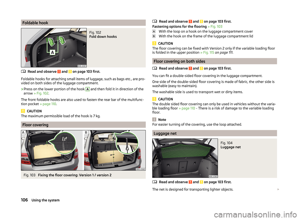
Foldable hookFig. 102
Fold down hooks
Read and observe and on page 103 first.
Foldable hooks for attaching small items of luggage, such as bags etc., are pro-
vided on both sides of the luggage compartment.
›
Press on the lower portion of the hook
A
and then fold it in direction of the
arrow » Fig. 102 .
The front foldable hooks are also used to fasten the rear bar of the multifunc-
tion pocket » page 110.
CAUTION
The maximum permissible load of the hook is 7 kg.
Floor covering
Fig. 103
Fixing the floor covering: Version 1 / version 2
Read and observe and on page 103 first.
Fastening options for the flooring » Fig. 103
With the loop on a hook on the luggage compartment cover
With the hook on the frame of the luggage compartment lid
CAUTION
The floor covering can be fixed with Version 2 only if the variable loading floor
is folded in the upper position » Fig. 115 on page 111 .
Floor covering on both sides
Read and observe
and on page 103 first.
You can fit a double-sided floor covering in the luggage compartment.
One side of the double-sided floor covering is made of fabric, the other side is
washable (easy to maintain).
The washable side is used to transport wet or dirty items.
CAUTION
The double sided floor covering can only be used in vehicles without the varia-
ble loading floor » page 110 - There is a risk of damage to the variable loading
floor.
Note
For easier turning of the covering, use the loop attached.
Luggage net
Fig. 104
Luggage net
Read and observe and on page 103 first.
The net is designed for transporting lighter objects.
106Using the system
Page 110 of 280

The luggage net is located on the underside of the luggage compartment cov-
er » Fig. 104 .WARNINGOnly store soft objects with a total weight of 1.5 kg in the net. Heavy ob-
jects are not secured sufficiently – risk of injury!
CAUTION
Do not place any sharp objects into the net – risk of net damage.
Luggage compartment cover
Fig. 105
Removing/installing the luggage compartment cover
Fig. 106
Luggage compartment cover
stowed behind the rear seats
Read and observe and on page 103 first.
The boot cover can be removed if you want to transport bulky goods.
Removing
›
Unhook the retaining straps
A
of the flap in the direction of arrow
1
» Fig. 105 .
›On the underside of the cover, in the area of the holders, press C.›Remove the cover in the direction of the arrow 2.
The removed boot cover can be stowed behind the seat backrest » Fig. 106.
Installing›
Place the cover on the contact surfaces of the side trim panel.
›
Place the recesses
B
» Fig. 105 on the cover of the
C
brackets on the side
cover.
›
Press on the upper side of the cover so that the mounts fully interlock in the
holders.
›
Insert the retaining bands
A
opposite to the direction of arrow
1
on the
boot lid.
WARNINGNo objects should be placed on the boot cover, the vehicle occupants could
be endangered if there is sudden braking or the vehicle collides with some-
thing.
CAUTION
■ When closing the boot lid, jamming and damage to the luggage compartment
cover or the side trim panel can occur if handled in an unprofessional way. The
following guidelines must be observed. ■ The recesses in the cover B
» Fig. 105 must lock in the holders in the side
trim panel
C
.
■ The items which are transported must not exceed the height of the lug-
gage compartment cover. ■ The cover must not be jammed in the surrounding seal of the luggage com-
partment lid when it is in the opened position.
■ There must be no object in the gap between the opened cover and the rear
backrest.
Note
If the support straps A » Fig. 105 are attached to the boot, then the boot cov-
er will rise as well when the luggage compartment is opened.107Transporting and practical equipment