fuel SKODA OCTAVIA 2014 3.G / (5E) Owner's Manual
[x] Cancel search | Manufacturer: SKODA, Model Year: 2014, Model line: OCTAVIA, Model: SKODA OCTAVIA 2014 3.G / (5E)Pages: 280, PDF Size: 35.53 MB
Page 6 of 280
General Maintenance
Care and maintenance177
Service work, adjustments and technical alterations
177
Washing vehicle
180
Cleaning vehicle exterior
181
Interior care
185
Inspecting and replenishing
188
Fuel
188
Engine compartment
192
Engine oil
195
Coolant
197
Brake fluid
199
Vehicle battery
200
Wheels
204
Tyres and wheel rims
204
Manufacturer-approved tyre variants
207
Winter operation
209
Do-it-yourself
Emergency equipment, and self-help
211
Emergency equipment
211
Reserve and temporary spare
213
Changing a wheel
214
Puncture repair kit
218
Jump-starting
220
Towing the vehicle
221
Remote control
224
Emergency unlocking/locking
225
Replacing windscreen wiper blades
226
Fuses and light bulbs
228
Fuses
228
Bulbs
231Technical data
Technical data238
Basic vehicle data
238
Vehicle-specific information depending on
engine type
246
Index
3Table of Contents
Page 10 of 280

AbbreviationsAbbreviationDefinitionrpmEngine revolutions per minuteABSAnti-lock brake systemACCAdaptive cruise controlAHLAdaptive headlightsAGAutomatic gearboxAGMVehicle battery typeTCSTraction controlCNGcompressed natural gasCO2Carbon dioxideDPFDiesel particle filterDSGAutomatic double clutch gearboxDSRActive driver-steering recommendationEDLElectronic differential lockECEEconomic Commission for EuropeEPCEPC fault lightESCElectronic Stability ControlDRim depthEUEuropean UnionG-TECLabelling for natural gas vehiclesGSMGlobal System for Mobile communicationsHBAHydraulic brake assistHHCUphill start assistKESSYkeyless unlocking, starting and lockingkWKilowatt, measuring unit for the engine outputMCBMulti-collision brakeMGManual gearboxMPIGasoline engine with a multi-point fuel injectionN1Panel van intended exclusively or mainly for the transporta-
tion of goodsNmNewton meter, measuring unit for the engine torqueAbbreviationDefinitionTDI CRDiesel engine with turbo charging and common-rail injection
systemTSATrailer stabilisationTSIPetrol engine with turbocharging and direct injectionVINVehicle identification numberWi-FiWireless data networkXDSFunctional expansion of the electronic differential lock7Abbreviations
Page 20 of 280
The airbags are not deployed in the case of minor frontal and side collisions,
rear-end collisions, tilting of the vehicle and vehicle rollover.
Deployment factors
It is not possible to generally determine which deployment conditions apply to
the airbag system in every situation. An important role is played by factors
such as the type of object that the vehicle hits (hard/soft), the impact angle,
vehicle speed, etc.
A decisive factor for the deployment of the airbags is the deceleration which
occurs. The control unit analyses the nature of the collision and activates the
relevant restraint system.
If the vehicle deceleration which occurs and is measured during the collision
remains below the prescribed reference values specified in the control unit,
the airbags are not deployed although the vehicle may well suffer severe dam-
age to the bodywork as a consequence of the accident.
The following airbags will be deployed in the event of a severe frontal
collision.
› Driver’s front airbag.
› Front passenger airbag.
› Driver’s knee airbag.
The following airbags will be deployed in the event of a severe side collision.
› Front side airbag on the side of the accident.
› Rear side airbag on the side of the accident.
› Head airbags on the side of the accident.
When an airbag is deployed, the following occurs.
› The interior lighting illuminates (if the switch for the interior lighting is in the
door contact position).
› The hazard warning lights are switched on.
› All the doors are unlocked.
› The fuel supply to the engine is interrupted.
Airbag overview
Introduction
This chapter contains information on the following subjects:
Front airbags
17
Driver’s knee airbag
18Side airbags19Head airbags20
Front airbags
Fig. 8
Locations of the airbags / gas filled airbags
Fig. 9
Safe distance to steering wheel
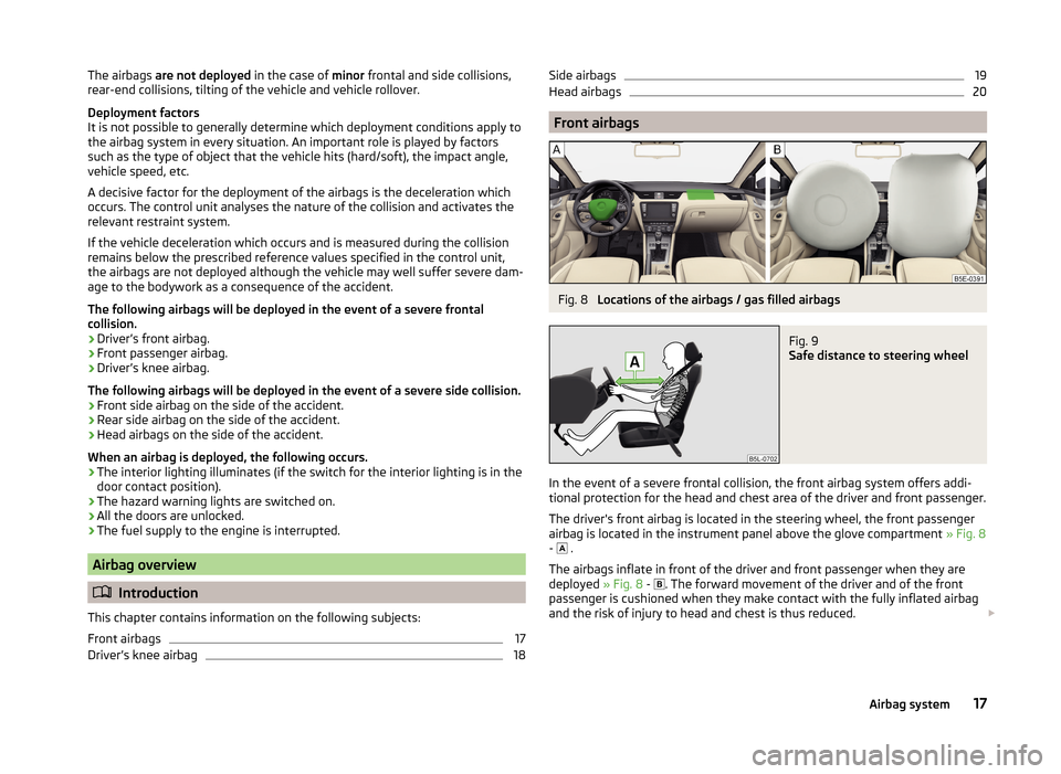
In the event of a severe frontal collision, the front airbag system offers addi-
tional protection for the head and chest area of the driver and front passenger.
The driver's front airbag is located in the steering wheel, the front passenger
airbag is located in the instrument panel above the glove compartment » Fig. 8
- .
The airbags inflate in front of the driver and front passenger when they are
deployed » Fig. 8 -
. The forward movement of the driver and of the front
passenger is cushioned when they make contact with the fully inflated airbag
and the risk of injury to head and chest is thus reduced.
17Airbag system
Page 33 of 280
Depending on equipment fitted:› USB/AUX input
» Infotainment Manual , chapter USB/AUX In-
puts
› MEDIA IN input
» Infotainment Manual , chapter MEDIA IN in-
put
Depending on equipment fitted: › Operating controls for the heating118
›Operating controls for the air conditioning system
119
›Operating controls for Climatronic
119
Note
The position of some of the controls on right-hand drive models may differ
from that shown in » Fig. 21. The symbols on the controls and switches are the
same as for left-hand drive models.3435Instruments and warning lights
Instrument cluster
Introduction
This chapter contains information on the following subjects:
Overview
31
Revolutions counter
31
Display
31
Speedometer
32
Coolant temperature gauge
32
Fuel reserve display - Natural gas
32
Fuel reserve display - Petrol / Diesel
33
Counter for distance driven
33
33
Viewing the charge level vehicle battery
34
The instrument cluster gives the driver basic information such as the current
speed, engine speed, the state of some vehicle systems and the like.
Fault display
If there is a fault in the instrument cluster, the following message will appear
in the display.
Error: instrument cluster. Workshop!
COMBINED INSTRUM_WORKSHOP
Seek help from a specialist garage.
WARNINGConcentrate fully at all times on your driving! As the driver you are fully re-
sponsible for road safety.
Note
If the message SAFE CP appears in the instrument cluster display, the compo-
nent protection for the instrument cluster is active. Further informa-
tion » page 179 , Component protection .30Using the system
Page 35 of 280
›Details of the information system
» page 45
› Messages of the Auto Check Control
» page 47
› Details of the service interval display
» page 53
CAUTION
Pull out the ignition key if coming in contact with the display (e.g. when clean-
ing) to prevent any possible damage. On vehicles with the KESSY system,
switch off the ignition and open the driver's door.
Note
Depending on vehicle equipment, the MAXI DOT display can be either mono-
chromatic “(black and white)” or color.
Speedometer
Read and observe
on page 30 first.
The speedometer
3
» Fig. 22 on page 31 displays the current speed.
Note
An audible warning signal will sound when the vehicle speed exceeds 120 km/
h 1)
. The audible warning signal is switched off when the vehicle speed falls be-
low 120 km/h.
Coolant temperature gauge
Fig. 24
Coolant temperature gauge
Read and observe on page 30 first.
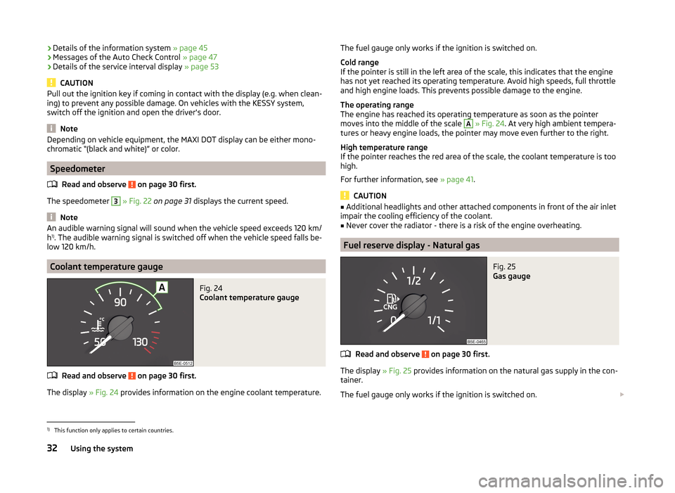
The display » Fig. 24 provides information on the engine coolant temperature.
The fuel gauge only works if the ignition is switched on.
Cold range
If the pointer is still in the left area of the scale, this indicates that the engine
has not yet reached its operating temperature. Avoid high speeds, full throttle
and high engine loads. This prevents possible damage to the engine.
The operating range
The engine has reached its operating temperature as soon as the pointer
moves into the middle of the scale A
» Fig. 24 . At very high ambient tempera-
tures or heavy engine loads, the pointer may move even further to the right.
High temperature range
If the pointer reaches the red area of the scale, the coolant temperature is too
high.
For further information, see » page 41.
CAUTION
■
Additional headlights and other attached components in front of the air inlet
impair the cooling efficiency of the coolant.■
Never cover the radiator - there is a risk of the engine overheating.
Fuel reserve display - Natural gas
Fig. 25
Gas gauge
Read and observe on page 30 first.
The display » Fig. 25 provides information on the natural gas supply in the con-
tainer.
The fuel gauge only works if the ignition is switched on.
1)
This function only applies to certain countries.
32Using the system
Page 36 of 280

If the natural gas supply in the container reaches the reserve area, the icon ap-
pears in the display together with the following message.
Please refuel with CNG. Range: ... km
An audible signal sounds as a warning signal.
Fuel reserve display - Petrol / Diesel
Fig. 26
Gasoline / diesel reserve display
Read and observe on page 30 first.
The display » Fig. 26 provides information of the petrol / diesel supply in the
container.
The display only works if the ignition is switched on.
The contents of the fuel tank for petrol / diesel is approximately 50 litres.
If the amount of fuel reaches the reserve area (the pointer reaches the red
scale range), the indicator symbol
» page 43 illuminates too.
CAUTION
Never drive until the fuel tank is completely empty! The irregular supply of fuel
can cause misfiring. This can result in considerable damage to parts of the en-
gine and the exhaust system.
Note
■ After filling up, it can occur that during dynamic driving (e.g. numerous
curves, braking, driving downhill and climbing a steep hill) the fuel gauge indi-
cates approx. a fraction less. When stopping or during less dynamic driving, the
fuel gauge displays the correct fuel level again. This is not a fault.■
The arrow
next to the icon
within the fuel gauge displays the installation
location of the fuel filler on the right side of the vehicle.
Counter for distance drivenFig. 27
Display: MAXI DOT display / Seg-
ment Display
Read and observe on page 30 first.
Display » Fig. 27
Counter for distance travelled (trip)
Odometer
Counter for distance travelled (trip)
The daily trip counter shows the distance driven since the time the counter
was last reset - in steps of 100 m.
Reset counter for distance travelled (trip)
›
Briefly press the button
6
» Fig. 22 on page 31 .
Odometer
The odometer indicates the total distance which the vehicle has been driven.
Read and observe on page 30 first.
›
Switch on the ignition.
›
Press and hold the button
6
» Fig. 22 on page 31 until the Time is shown in
the display.
›
Release the button
6
, and the system switches to the time setting function.
›
Press the button
6
again and set the hours.
›
Wait around 4 seconds - the system switches to the minutes setting.
›
Press the button
6
again and set the minutes.
›
Wait around 4 seconds - the system switches to the minutes setting.
The time can also be set in the Infotainment » operating instructions for Info-
tainment , chapter Device settings .
AB33Instruments and warning lights
Page 43 of 280
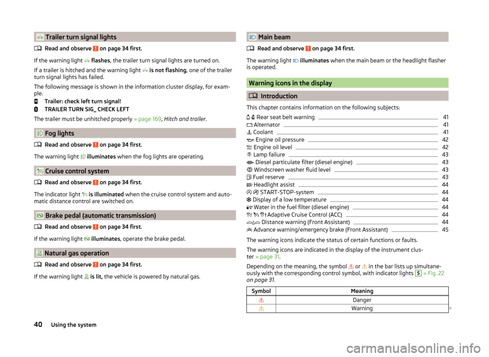
Trailer turn signal lightsRead and observe
on page 34 first.
If the warning light
flashes , the trailer turn signal lights are turned on.
If a trailer is hitched and the warning light
is not flashing , one of the trailer
turn signal lights has failed.
The following message is shown in the information cluster display, for exam-
ple.
Trailer: check left turn signal!
TRAILER TURN SIG_ CHECK LEFT
The trailer must be unhitched properly » page 169, Hitch and trailer .
Fog lights
Read and observe
on page 34 first.
The warning light
illuminates when the fog lights are operating.
Cruise control system
Read and observe
on page 34 first.
The indicator light
is illuminated when the cruise control system and auto-
matic distance control are switched on.
Brake pedal (automatic transmission)
Read and observe
on page 34 first.
If the warning light
illuminates , operate the brake pedal.
Natural gas operation
Read and observe
on page 34 first.
If the warning light
is lit, the vehicle is powered by natural gas.
Main beam
Read and observe
on page 34 first.
The warning light
illuminates when the main beam or the headlight flasher
is operated.
Warning icons in the display
Introduction
This chapter contains information on the following subjects:
Rear seat belt warning
41
Alternator
41
Coolant
41
Engine oil pressure
42
Engine oil level
42
Lamp failure
43
Diesel particulate filter (diesel engine)
43
Windscreen washer fluid level
43
Fuel reserve
43
Headlight assist
44
START-STOP-system
44
Display of a low temperature
44
Water in the fuel filter (diesel engine)
44
Adaptive Cruise Control (ACC)
44
Distance warning (Front Assistant)
44
Advance warning/emergency brake (Front Assistant)
45
The warning icons indicate the status of certain functions or faults.
The warning icons are indicated in the display of the instrument clus-
ter » page 31 .
Depending on the meaning, the symbol or
in the bar lists up simultane-
ously with the corresponding control symbol, with indicator lights
5
» Fig. 22
on page 31 .
SymbolMeaningDangerWarning 40Using the system
Page 46 of 280
Lamp failureRead and observe
on page 41 first.
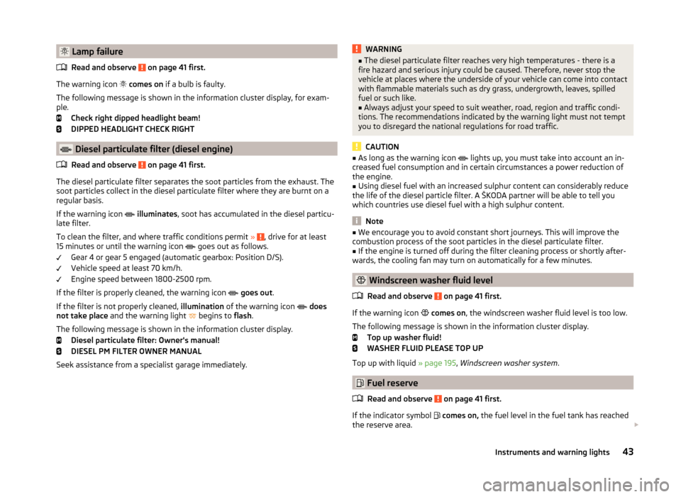
The warning icon
comes on if a bulb is faulty.
The following message is shown in the information cluster display, for exam-
ple.
Check right dipped headlight beam!
DIPPED HEADLIGHT CHECK RIGHT
Diesel particulate filter (diesel engine)
Read and observe
on page 41 first.
The diesel particulate filter separates the soot particles from the exhaust. The
soot particles collect in the diesel particulate filter where they are burnt on a
regular basis.
If the warning icon
illuminates , soot has accumulated in the diesel particu-
late filter.
To clean the filter, and where traffic conditions permit »
, drive for at least
15 minutes or until the warning icon goes out as follows.
Gear 4 or gear 5 engaged (automatic gearbox: Position D/S).
Vehicle speed at least 70 km/h.
Engine speed between 1800-2500 rpm.
If the filter is properly cleaned, the warning icon
goes out .
If the filter is not properly cleaned, illumination of the warning icon
does
not take place and the warning light
begins to
flash.
The following message is shown in the information cluster display. Diesel particulate filter: Owner's manual!
DIESEL PM FILTER OWNER MANUAL
Seek assistance from a specialist garage immediately.
WARNING■ The diesel particulate filter reaches very high temperatures - there is a
fire hazard and serious injury could be caused. Therefore, never stop the
vehicle at places where the underside of your vehicle can come into contact
with flammable materials such as dry grass, undergrowth, leaves, spilled
fuel or such like.■
Always adjust your speed to suit weather, road, region and traffic condi-
tions. The recommendations indicated by the warning light must not tempt
you to disregard the national regulations for road traffic.
CAUTION
■ As long as the warning icon lights up, you must take into account an in-
creased fuel consumption and in certain circumstances a power reduction of
the engine.■
Using diesel fuel with an increased sulphur content can considerably reduce
the life of the diesel particle filter. A ŠKODA partner will be able to tell you
which countries use diesel fuel with a high sulphur content.
Note
■ We encourage you to avoid constant short journeys. This will improve the
combustion process of the soot particles in the diesel particulate filter.■
If the engine is turned off during the filter cleaning process or shortly after-
wards, the cooling fan may turn on automatically for a few minutes.
Windscreen washer fluid level
Read and observe
on page 41 first.
If the warning icon
comes on , the windscreen washer fluid level is too low.
The following message is shown in the information cluster display. Top up washer fluid!
WASHER FLUID PLEASE TOP UP
Top up with liquid » page 195, Windscreen washer system .
Fuel reserve
Read and observe
on page 41 first.
If the indicator symbol
comes on, the fuel level in the fuel tank has reached
the reserve area.
43Instruments and warning lights
Page 47 of 280
The following message is shown in the information cluster display.Please refuel. Range: ... km
PLEASE REFUEL RANGE …
An audible signal sounds as a warning signal.
CAUTION
Never drive until the fuel tank is completely empty! The irregular supply of fuel
can cause misfiring. This can result in considerable damage to parts of the en-
gine and the exhaust system.
Note
The text in the display goes out after refuelling and driving a short distance.
Headlight assist
Read and observe
on page 41 first.
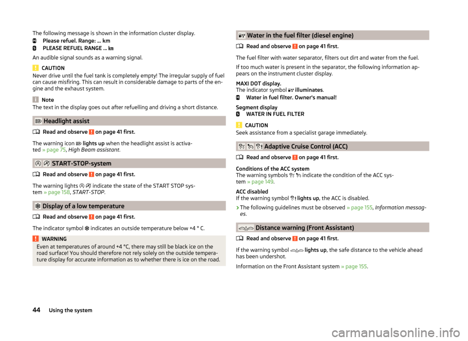
The warning icon
lights up when the headlight assist is activa-
ted » page 75 , High Beam assistant .
START-STOP-system
Read and observe
on page 41 first.
The warning lights
indicate the state of the START STOP sys-
tem » page 158 , START-STOP .
Display of a low temperature
Read and observe
on page 41 first.
The indicator symbol
indicates an outside temperature below +4 ° C.
WARNINGEven at temperatures of around +4 °C, there may still be black ice on the
road surface! You should therefore not rely solely on the outside tempera-
ture display for accurate information as to whether there is ice on the road. Water in the fuel filter (diesel engine)
Read and observe
on page 41 first.
The fuel filter with water separator, filters out dirt and water from the fuel.
If too much water is present in the separator, the following information ap-
pears on the instrument cluster display.
MAXI DOT display.
The indicator symbol
illuminates .
Water in fuel filter. Owner's manual!
Segment display WATER IN FUEL FILTER
CAUTION
Seek assistance from a specialist garage immediately.
Adaptive Cruise Control (ACC)
Read and observe
on page 41 first.
Conditions of the ACC system
The warning symbols
indicate the condition of the ACC sys-
tem » page 149 .
ACC disabled
If the warning symbol
lights up , the ACC is disabled.
›
The following guidelines must be observed » page 155, Information messag-
es .
Distance warning (Front Assistant)
Read and observe
on page 41 first.
If the warning symbol
lights up , the safe distance to the vehicle ahead
has been undershot.
Information on the Front Assistant system » page 155.
44Using the system
Page 49 of 280
Using the information systemFig. 28
Buttons/adjustment wheel: on the operating lever/on the multi-
function steering wheel
Read and observe
on page 45 first.
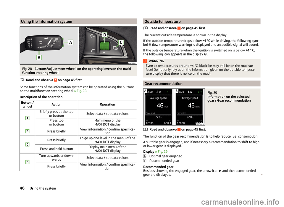
Some functions of the information system can be operated using the buttons
on the multifunction steering wheel » Fig. 28.
Description of the operation
Button / wheelActionOperationABriefly press at the top or bottomSelect data / set data valuesPress top
or bottomMain menu of the MAXI DOT displayBPress brieflyView information / confirm specifica- tionCPress brieflyTo go up one level in the menu of theMAXI DOT displayPress and hold buttonDisplay main menu of theMAXI DOT displayDTurn upwards or down- wardsSelect data / set data valuesPress brieflyView information / confirm specifica- tionOutside temperature
Read and observe
on page 45 first.
The current outside temperature is shown in the display.
If the outside temperature drops below +4 °C while driving, the following sym-
bol
(low temperature warning) is displayed and an audible signal will sound.
If the outside temperature when the ignition is switched on is below +4 ° C,
the following icon appears in the display
.
WARNINGEven at temperatures around +4 °C, black ice may still be on the road sur-
face! Do not only rely upon the information given on the outside tempera-
ture display that there is no ice on the road.
Gear recommendation
Fig. 29
Information on the selected
gear / Gear recommendation
Read and observe on page 45 first.
The function of the gear recommendation is to help reduce fuel consumption.
A suitable gear is engaged, and if necessary a recommendation to shift to high
or lower gear is displayed.
Display » Fig. 29
Optimal gear engaged
Recommended gear
Recommended gear
Besides showing the engaged gear, the arrow icon
and the recommended
gear are displayed.
46Using the system