check engine light SKODA OCTAVIA 2014 3.G / (5E) Owner's Guide
[x] Cancel search | Manufacturer: SKODA, Model Year: 2014, Model line: OCTAVIA, Model: SKODA OCTAVIA 2014 3.G / (5E)Pages: 280, PDF Size: 35.53 MB
Page 194 of 280
CAUTION■Just filling the tank once with diesel fuel that does not comply with the
standard, can cause severe damage to parts of the engine, the fuel and ex-
haust system!■
If a different fuel other than diesel fuel, which complies to the above men-
tioned standards (e.g. petrol) is used, do not start the engine or switch on the
ignition! Extensive damage to engine parts can occur!
■
Water which has collected in the fuel filter can cause engine faults.
CAUTION
■ The vehicle cannot be operated with bio fuel RME, therefore this fuel must
not be filled in the tank and used for driving the vehicle. The use of biofuel
RME can cause considerable damage to parts of the engine or fuel system.■
Do not mix any fuel additives, so-called “flow improvers” (petrol and similar
agents) into the diesel. This can result in considerable damage to parts of the
engine or the exhaust system.
Refuelling with CNG (compressed natural gas)
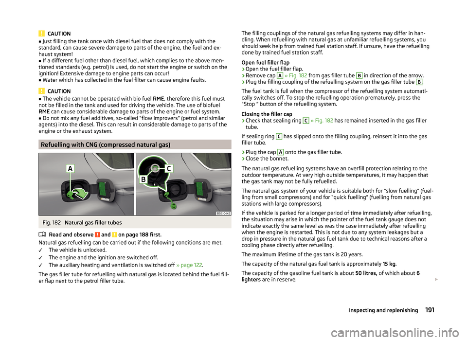
Fig. 182
Natural gas filler tubes
Read and observe
and on page 188 first.
Natural gas refuelling can be carried out if the following conditions are met. The vehicle is unlocked.
The engine and the ignition are switched off.
The auxiliary heating and ventilation is switched off » page 122.
The gas filler tube for refuelling with natural gas is located behind the fuel fill- er flap next to the petrol filler tube.
The filling couplings of the natural gas refuelling systems may differ in han-
dling. When refuelling with natural gas at unfamiliar refuelling systems, you
should seek help from trained fuel station staff. If unsure, have the refuelling done by trained fuel station staff.
Open fuel filler flap›
Open the fuel filler flap.
›
Remove cap
A
» Fig. 182 from gas filler tube
B
in direction of the arrow.
›
Plug the filling coupling of the refuelling system on the gas filler tube
B
.
The fuel tank is full when the compressor of the refuelling system automati-
cally switches off. To stop the refuelling operation prematurely, press the
“Stop ” button of the refuelling system.
Closing the filler cap
›
Check that sealing ring
C
» Fig. 182 has remained inserted in the gas filler
tube.
If sealing ring
C
has slipped onto the filling coupling, reinsert it into the gas
filler tube.
›
Plug the cap
A
onto the gas filler tube.
›
Close the bonnet.
The natural gas refuelling systems have an overfill protection relating to the
outdoor temperature. At very high outside temperatures, it may happen that
the gas tank may not be fully refuelled.
The natural gas system of your vehicle is suitable both for “slow fuelling” (fuel-
ling from small compressors) and for “quick fuelling” (fuelling from natural gas
stations with large compressors).
If the vehicle is parked for a longer period of time immediately after refuelling,
the situation may arise in which the pointer of the fuel tank gauge does not
indicate exactly the same level as was the case immediately after refuelling
when the engine is restarted. This is not due to any system leakages but a
drop in pressure in the natural gas fuel tank due to technical reasons after a
cooling phase directly after refuelling.
The maximum lifetime of the gas tank is 20 years.
The capacity of the natural gas fuel tank is approximately 15 kg.
The capacity of the gasoline fuel tank is about 50 litres, of which about 6
lighters are in reserve.
191Inspecting and replenishing
Page 198 of 280
NoteThe location of the inspection points in the engine compartment of petrol and
diesel engines is practically identical.
Radiator fan
Read and observe
and on page 193 first.
The radiator fan is powered by an electric motor. Operation is controlled ac-
cording to the temperature of the coolant.
WARNINGAfter switching off the ignition, the fan can intermittently continue to oper-
ate for approx. 10 minutes.
Windscreen washer system
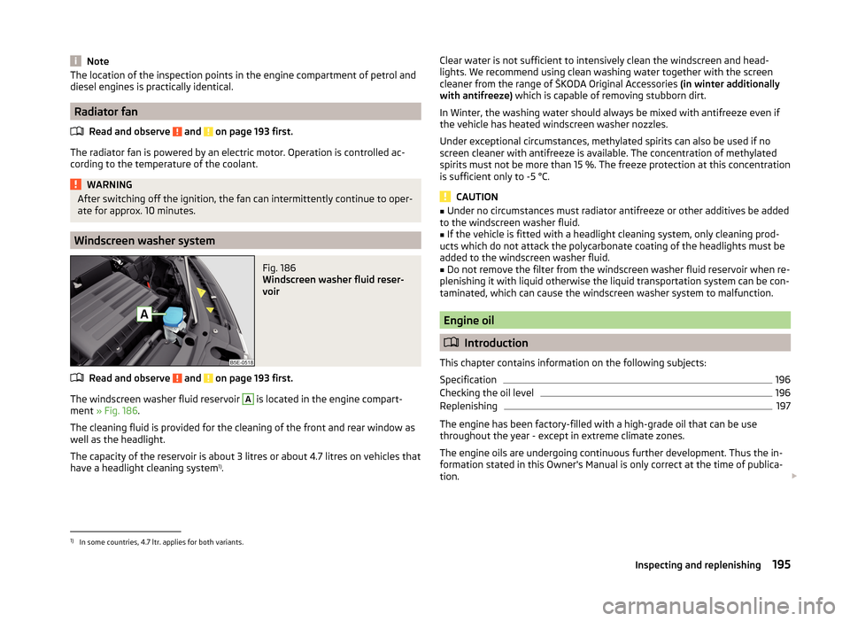
Fig. 186
Windscreen washer fluid reser-
voir
Read and observe and on page 193 first.
The windscreen washer fluid reservoir
A
is located in the engine compart-
ment » Fig. 186 .
The cleaning fluid is provided for the cleaning of the front and rear window as
well as the headlight.
The capacity of the reservoir is about 3 litres or about 4.7 litres on vehicles that
have a headlight cleaning system 1)
.
Clear water is not sufficient to intensively clean the windscreen and head-
lights. We recommend using clean washing water together with the screen
cleaner from the range of ŠKODA Original Accessories (in winter additionally
with antifreeze) which is capable of removing stubborn dirt.
In Winter, the washing water should always be mixed with antifreeze even if
the vehicle has heated windscreen washer nozzles.
Under exceptional circumstances, methylated spirits can also be used if no
screen cleaner with antifreeze is available. The concentration of methylated
spirits must not be more than 15 %. The freeze protection at this concentration
is sufficient only to -5 °C.
CAUTION
■ Under no circumstances must radiator antifreeze or other additives be added
to the windscreen washer fluid.■
If the vehicle is fitted with a headlight cleaning system, only cleaning prod-
ucts which do not attack the polycarbonate coating of the headlights must be
added to the windscreen washer fluid.
■
Do not remove the filter from the windscreen washer fluid reservoir when re-
plenishing it with liquid otherwise the liquid transportation system can be con-
taminated, which can cause the windscreen washer system to malfunction.
Engine oil
Introduction
This chapter contains information on the following subjects:
Specification
196
Checking the oil level
196
Replenishing
197
The engine has been factory-filled with a high-grade oil that can be use
throughout the year - except in extreme climate zones.
The engine oils are undergoing continuous further development. Thus the in- formation stated in this Owner's Manual is only correct at the time of publica-
tion.
1)
In some countries, 4.7 ltr. applies for both variants.
195Inspecting and replenishing
Page 200 of 280
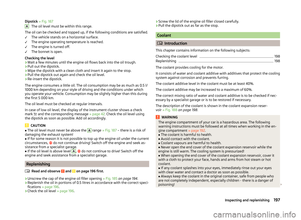
Dipstick » Fig. 187
The oil level must be within this range.
The oil can be checked and topped up, if the following conditions are satisfied. The vehicle stands on a horizontal surface.
The engine operating temperature is reached.
The engine is turned off.
The bonnet is open.
Checking the level›
Wait a few minutes until the engine oil flows back into the oil trough.
›
Pull out the dipstick.
›
Wipe the dipstick with a clean cloth and insert it again to the stop.
›
Pull the dipstick out again and check the oil level.
›
Re-insert the dipstick.
The engine consumes a little oil. The oil consumption may be as much as 0.5 l/
1000 km depending on your style of driving and the conditions under which
you operate your vehicle. Consumption may be slightly higher than this during
the first 5 000 km.
The oil level must be checked at regular intervals.
In case of low oil level, the display of the instrument cluster shows a check
mark and the corresponding message
» page 42. Check the oil level using
the dipstick as soon as possible. Add oil accordingly.
CAUTION
■ The oil level must never be above the A range » Fig. 187 – there is a risk of
damaging the exhaust system!■
If for some reason it is not possible to top up the engine oil under the current
circumstances,
do not continue driving! Switch off the engine and seek as-
sistance from a specialist garage.
■
If the oil level is above level
A
,
do not continue to drive! Switch off the
engine and seek assistance from a specialist garage.
Replenishing
Read and observe
and on page 196 first.
›
Unscrew the cap of the engine oil filler opening » Fig. 185 on page 194 .
›
Replenish the oil in portions of 0.5 litres in accordance with the correct speci-
fications » page 196 .
›
Check the oil level » page 196.
A›Screw the lid of the engine oil filler closed carefully.›Pull the dipstick out as far as the stop.
Coolant
Introduction
This chapter contains information on the following subjects:
Checking the coolant level
198
Replenishing
198
The coolant provides cooling for the motor.
It consists of water and coolant additive with additives that protect the cooling
system against corrosion and prevents furring.
The coolant additive level in the coolant must be at least 40%.
The coolant additive may be increased to a maximum of 60%.
The correct mixing ratio of water and coolant additive is to be checked if nec- essary by a specialist garage or is to be restored if necessary.
The description of the coolant is shown in the coolant expansion reser-
voir » Fig. 188 on page 198 .
WARNINGThe engine compartment of your car is a hazardous area. The following
warning instructions must be followed at all times when working in the en- gine compartment » page 192.■
The coolant is harmful to health.
■
Avoid contact with the coolant.
■
Coolant vapours are harmful to health.
■
Never open the end cover of the coolant expansion reservoir while the
engine is still warm. The cooling system is pressurized!
■
When opening the end cover of the coolant expansion reservoir, cover it
with a cloth to protect your face, hands and arms from hot steam or hot
coolant.
■
If any coolant splashes into your eyes, immediately rinse out your eyes
with clear water and contact a doctor as soon as possible.
■
Always keep the coolant in the original container, safe from people who
are not completely independent, especially children - there is a danger of
poisoning!
197Inspecting and replenishing
Page 201 of 280
WARNING (Continued)■If coolant is swallowed, consult a doctor immediately.■Never spill operating fluids over the hot engine - risk of fire.
CAUTION
■If for some reason it is not possible to top up the coolant under the current
circumstances, do not continue driving! Switch off the engine and seek as-
sistance from a specialist garage.■
If the expansion tank is empty, do not top up with coolant. The system could
aerate - risk of engine damage,
do not continue driving! Switch off the en-
gine and seek assistance from a specialist garage.
■
The amount of coolant additive in the coolant must never be allowed to be
less than 40 %.
■
Over 60 % of coolant additive in the coolant reduces the antifreeze protec-
tion and coolant effectiveness.
■
A coolant additive that does not comply with the correct specification can
significantly reduce the corrosion protection of the cooling system.
■
Any faults resulting from corrosion may cause a loss of coolant and can con-
sequently result in major engine damage!
■
Do not fill the coolant above the mark
A
» Fig. 188 on page 198 .
■
If an error occurs, leading to the engine overheating, the help of a professio-
nal garage is to be sought - there is a risk of serious engine damage occurring.
■
Additional headlights and other attached components in front of the air inlet
impair the cooling efficiency of the coolant.
■
Never cover the radiator - there is a risk of the engine overheating.
Note
On vehicles that are fitted with an auxiliary heater (auxiliary heating and venti-
lation), the coolant capacity is approx. 1 l larger.
Checking the coolant level
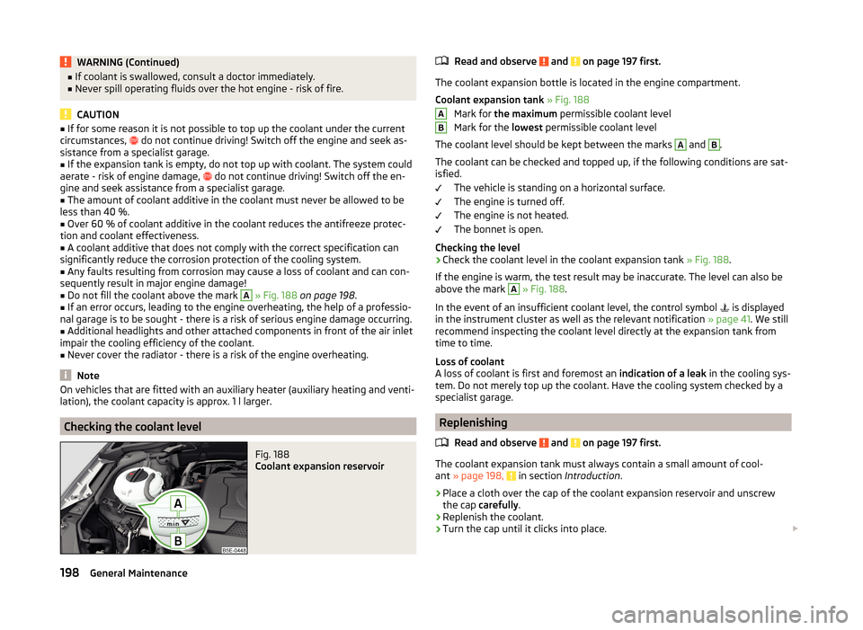
Fig. 188
Coolant expansion reservoir
Read and observe and on page 197 first.
The coolant expansion bottle is located in the engine compartment.
Coolant expansion tank » Fig. 188
Mark for the maximum permissible coolant level
Mark for the lowest permissible coolant level
The coolant level should be kept between the marks
A
and
B
.
The coolant can be checked and topped up, if the following conditions are sat-
isfied.
The vehicle is standing on a horizontal surface.
The engine is turned off.
The engine is not heated.
The bonnet is open.
Checking the level
›
Check the coolant level in the coolant expansion tank » Fig. 188.
If the engine is warm, the test result may be inaccurate. The level can also be
above the mark
A
» Fig. 188 .
In the event of an insufficient coolant level, the control symbol is displayed
in the instrument cluster as well as the relevant notification » page 41. We still
recommend inspecting the coolant level directly at the expansion tank from
time to time.
Loss of coolant
A loss of coolant is first and foremost an indication of a leak in the cooling sys-
tem. Do not merely top up the coolant. Have the cooling system checked by a
specialist garage.
Replenishing
Read and observe
and on page 197 first.
The coolant expansion tank must always contain a small amount of cool-
ant » page 198, in section Introduction .
›
Place a cloth over the cap of the coolant expansion reservoir and unscrew
the cap carefully .
›
Replenish the coolant.
›
Turn the cap until it clicks into place.
AB198General Maintenance
Page 202 of 280
CAUTION■Only refill with new coolant.■Do not use an alternative additive if the specified coolant is not available. In
this case, use just water and have the correct mixing ratio of water and cool-
ant additive restored by a specialist garage as soon as possible.
Brake fluid
Introduction
This chapter contains information on the following subjects:
Checking the brake fluid level
199
Specification
199
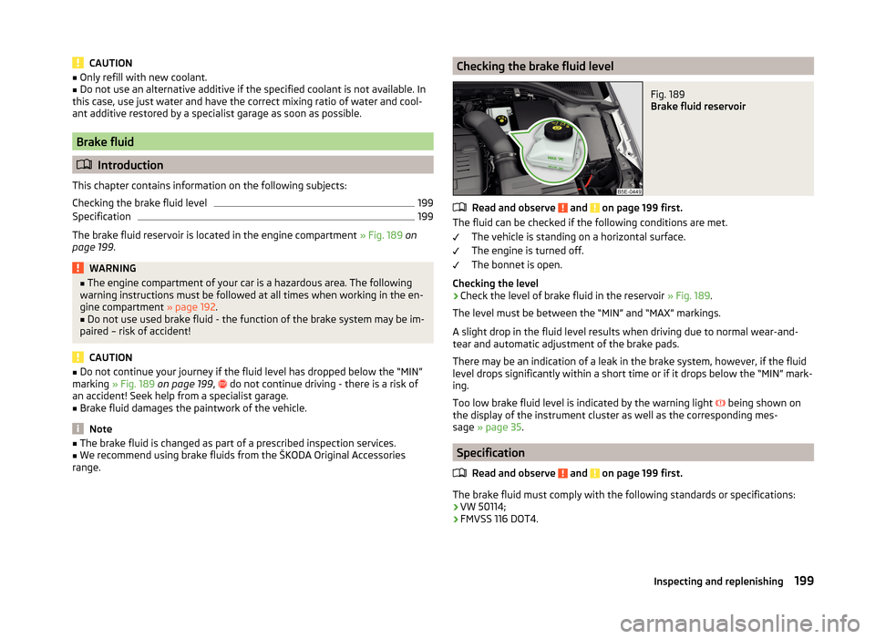
The brake fluid reservoir is located in the engine compartment » Fig. 189 on
page 199 .
WARNING■
The engine compartment of your car is a hazardous area. The following
warning instructions must be followed at all times when working in the en-
gine compartment » page 192.■
Do not use used brake fluid - the function of the brake system may be im-
paired – risk of accident!
CAUTION
■ Do not continue your journey if the fluid level has dropped below the “MIN”
marking » Fig. 189 on page 199 , do not continue driving - there is a risk of
an accident! Seek help from a specialist garage.■
Brake fluid damages the paintwork of the vehicle.
Note
■ The brake fluid is changed as part of a prescribed inspection services.■We recommend using brake fluids from the ŠKODA Original Accessories
range.Checking the brake fluid levelFig. 189
Brake fluid reservoir
Read and observe and on page 199 first.
The fluid can be checked if the following conditions are met.
The vehicle is standing on a horizontal surface.
The engine is turned off.
The bonnet is open.
Checking the level
›
Check the level of brake fluid in the reservoir » Fig. 189.
The level must be between the “MIN” and “MAX” markings.
A slight drop in the fluid level results when driving due to normal wear-and-
tear and automatic adjustment of the brake pads.
There may be an indication of a leak in the brake system, however, if the fluid
level drops significantly within a short time or if it drops below the “MIN” mark-
ing.
Too low brake fluid level is indicated by the warning light being shown on
the display of the instrument cluster as well as the corresponding mes-
sage » page 35 .
Specification
Read and observe
and on page 199 first.
The brake fluid must comply with the following standards or specifications:› VW 50114;
› FMVSS 116 DOT4.
199Inspecting and replenishing
Page 204 of 280

■Do not place the battery in direct daylight in order to protect the vehicle bat-
tery housing from the effects of ultra-violet light.■
If the vehicle is frequently used for making short trips, the vehicle battery
will not have time to charge up sufficiently and may discharge.
For the sake of the environment
A vehicle battery that has been removed is a special type of hazardous waste.
These must be disposed of in accordance with national legal regulations.
Note
■ We recommend having all work on the vehicle battery carried out by a spe-
cialist garage.■
You should replace batteries older than 5 years.
Opening the cover
Fig. 190
Polyester cover of vehicle bat-
tery
Read and observe and on page 200 first.
The battery is located in the engine compartment. For some equipment var-
iants, it is located underneath a polyester cover » Fig. 190.
›
Fold out the cover on the battery in the direction of the arrow.
The battery cover is installed in reverse order.
Checking the battery electrolyte levelFig. 191
Vehicle battery: Electrolyte level
indicator
Read and observe and on page 200 first.
On vehicles with a vehicle battery fitted with a colour indicator » Fig. 191, the
electrolyte level can be determined by looking at the change in colour of this
display.
Air bubbles can influence the colour of the indicator. For this reason carefully
knock on the indicator before carrying out the check.
› Black colour – electrolyte level is correct.
› Colourless or light yellow colour – electrolyte level too low, the battery must
be replaced.
Vehicles with a START-STOP system are fitted with a battery control unit for
checking the energy level for the recurring engine start.
We recommend that you have the acid level checked regularly by a specialist
garage, especially in the following cases.
› High external temperatures.
› Longer day trips.
› After each charge.
Winter time
The vehicle battery only has a proportion of the starting power in lower tem-
peratures. A discharged vehicle battery may already freeze at temperatures
just below 0 °C .
We therefore recommend that you have the battery checked and, if necessary,
recharged by a specialist garage before the start of the winter.
201Inspecting and replenishing
Page 206 of 280
›Firstly disconnect the battery's negative terminal
, followed by the positive
terminal .
Connecting›
Firstly connect the battery's positive terminal
, followed by the negative
terminal
.
After disconnecting and re-connecting the vehicle battery, the following func- tions or devices are partially or completely inoperative.
Function / deviceOperating measureElectrical power windows» page 66Panorama sliding/tilting roof» page 68Sun screen» page 70
Radio or navigation system
Enter code » Operating instruc-
tions for Infotainment Radio
or » Operating instructions for
Infotainment NavigationTime settings» page 33
CAUTION
■ Disconnect the vehicle battery only with the ignition turned off - there is a
risk of damaging the electrical system of the vehicle.■
Under no circumstances must the battery cables be connected incorrectly –
risk of a cable fire.
Note
■ After disconnecting and re-connecting the vehicle battery, we recommend
having the vehicle checked by a specialist to ensure that the full functionality
of all electrical systems is guaranteed.■
The data of the multi-function display will be reset.
Automatic load deactivation
Read and observe
and on page 200 first.
The vehicle voltage control unit automatically prevents the battery from dis-
charging when the bettery is subjected to heavy loads. This manifests itself by
the following.
› The idling speed is raised to allow the generator to deliver more electricity to
the electrical system.
› Where appropriate large convenience consumers, e.g. seat heaters, rear win-
dow heaters, have their power limited or in case of emergency shut off com-
pletely.
CAUTION
■ Despite such intervention by the vehicle electric system management, the
vehicle battery may be drained. For example, when the ignition is switched on
a long time with the engine turned off or the side or parking lights are turned
on during longer parking.■
Consumers which are supplied via a 12 V socket can cause the vehicle battery
to discharge when the ignition is switched off.
Note
Driving comfort is not disrupted by any shutting off of consumers. Often the
driver is not aware of it having taken place.203Inspecting and replenishing
Page 222 of 280
General informationRead and observe
on page 218 first.
For your own safety and the safety of your passengers, the following instruc-
tions must be observed before carrying out a wheel repair on the road.
Switch on the hazard warning light.
The warning triangle must be set up at the prescribed distance - observe
the national legal provisions when doing so.
Park the vehicle as far away as possible from the flow of traffic.
Choose a location with a flat, solid surface.
Have all the occupants get out of the vehicle. While changing a tyre, the
occupants of the vehicle should not stand on the road (they should in-
stead remain behind a crash barrier).
The national legal requirements must be observed when repairing a tyre.
The breakdown kit must not be used under the following circumstances. › The rim is damaged.
› The outside temperature is below -20 ° C.
› The cut or puncture is larger than 4 mm.
› The tyre wall is damaged.
› The result will be to drive with very low tyre pressure or with a completely
flat tyre.
› The expiration date has passed (see inflation bottle).
Preparations for using the breakdown kit
Read and observe
on page 218 first.
The following preparatory work must be carried out before using the puncture
repair kit.
›
Switch off the engine.
›
Engage first gear or place the selector lever of the automatic transmission
into the P position .
›
Firmly apply the handbrake.
›
Check that you can carry out the repairs with the breakdown kit » page 218.
›
Uncouple any trailers.
›
Remove the breakdown kit from the luggage compartment.
›
Stick the sticker
1
» Fig. 204 on page 218 on the dashboard in the driver's
field of view.
›
Unscrew the valve cap.
› Use the valve remover 2 to unscrew the valve core and place it on a clean
surface (rag, paper, etc.).
Sealing and inflating the tyre
Read and observe
on page 218 first.
Sealing
›
Forcefully shake the tyre inflater bottle
10
» Fig. 204 on page 218 back and
forth several times.
›
Firmly screw the inflation hose
3
onto the tyre inflator bottle
10
clockwise.
The film on the cap is pierced automatically.
›
Remove the plug from the inflation hose
3
and plug the open end fully onto
the tyre valve.
›
Hold the bottle
10
with the bottom facing upwards and fill all of the sealing
agent from the tyre inflator bottle into the tyre.
›
Remove the empty tyre inflator bottle from the valve.
›
Screw the valve core back into the tyre valve using the valve remover
2
.
Inflating
›
Screw the air compressor tyre inflation hose
7
» Fig. 204 on page 218 firmly
onto the tyre valve.
›
Start the engine and run it in idle.
›
Plug the connector
6
into 12 Volt socket » page 98.
›
Switch on the air compressor with the ON and OFF switch
9
.
›
Allow the air compressor to run until a pressure of 2.0 - 2.5 bar is achieved.
Maximum run time of 8 minutes » .
›
Switch off the air compressor.
›
If you cannot reach an air pressure of 2.0 – 2.5 bar, unscrew the tyre inflation
hose
7
from the tyre valve.
›
Drive the vehicle 10 metres forwards or backwards to allow the sealing agent
to “distribute” in the tyre.
›
Firmly screw the tyre inflation hose
7
back onto the tyre valve and repeat
the inflation process.
›
If you cannot reach the required tyre inflation pressure here either, this
means the tyre has sustained too much damage. You cannot seal with tyre with the breakdown kit »
.
›
Switch off the air compressor.
›
Remove the tyre inflation hose
7
from the tyre valve.
Once a tyre inflation pressure of 2.0 – 2.5 bar is achieved, continue the journey
at a maximum speed of 80 km/h (50 mph).
219Emergency equipment, and self-help
Page 231 of 280
Fuses and light bulbs
Fuses
Introduction
This chapter contains information on the following subjects:
Fuses in the dash panel – LHD
228
Fuses in the dash panel – RHD
229
Assignment of the fuses in the dash panel
229
Fuses in the engine compartment
230
Assignment of fuses in the engine compartment
231
Individual electrical circuits are protected by fuses.
Switch off the ignition and the corresponding power consuming device before
replacing a fuse.
Find out which fuse belongs to the component that is not operat-
ing » page 229 , Assignment of the fuses in the dash panel or » page 231 , As-
signment of fuses in the engine compartment .
Electrically adjustable seats are protected by automatic circuit breakers, which
switch on again automatically after a few seconds after the overload has been
eliminated.
Fuse colourMaximum amperagelight brown5dark brown7.5red10blue15yellow/blue20white25green/pink30orange/green40red50WARNINGAlways read and observe the warnings before completing any work in the
engine compartment » page 192.CAUTION■
“Never repair” fuses, and do not replace them with fuses of a higher amper-
age – risk of fire! This may also cause damage at other points in the electrical
system.■
If a newly inserted fuse blows again after a short time, have the electrical
system checked as quickly as possible by a specialist garage.
■
A blown fuses is recognisable by the molten metal strip. Replace the faulty
fuse with a new one of the same amperage.
Note
■
We recommend always carrying replacement fuses in the vehicle. A box of
replacement fuses can be purchased from ŠKODA Original Accessories.■
There can be several power consuming devices for one fuse.
■
Multiple fuses may exist for a single power consuming device.
Fuses in the dash panel – LHD
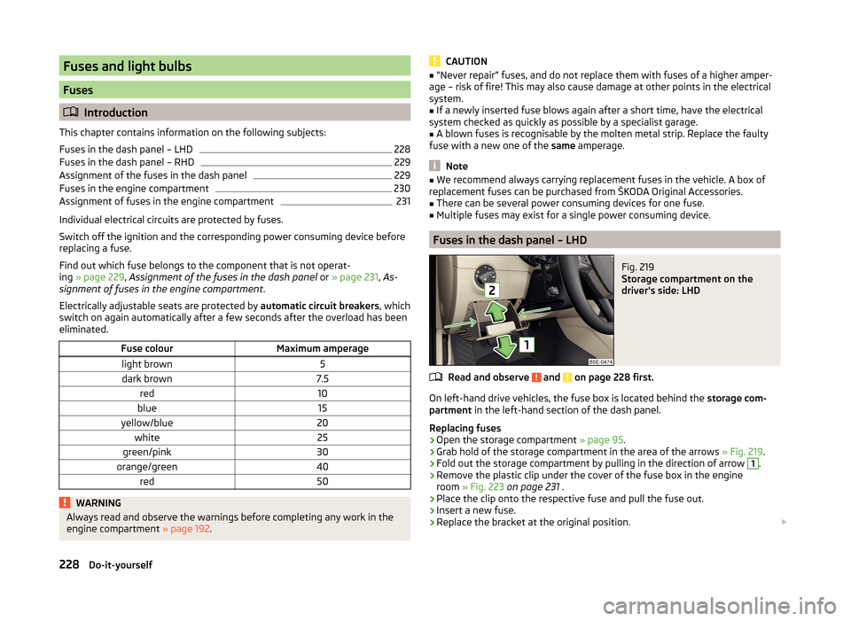
Fig. 219
Storage compartment on the
driver's side: LHD
Read and observe and on page 228 first.
On left-hand drive vehicles, the fuse box is located behind the storage com-
partment in the left-hand section of the dash panel.
Replacing fuses
›
Open the storage compartment » page 95.
›
Grab hold of the storage compartment in the area of the arrows » Fig. 219.
›
Fold out the storage compartment by pulling in the direction of arrow
1
.
›
Remove the plastic clip under the cover of the fuse box in the engine
room » Fig. 223 on page 231 .
›
Place the clip onto the respective fuse and pull the fuse out.
›
Insert a new fuse.
›
Replace the bracket at the original position.
228Do-it-yourself
Page 235 of 280
Change bulb for long-distance, daytime running lights and parking light
switch233
Change bulb for additional parking light
233
Change bulb for fog light switch - Variant 1
234
Change bulb for fog light switch - Variant 2
234
Replacing the bulb for the licence plate light
235
Rear Light
235
Replacing bulbs in the rear light - Variant 1
236
Replacing bulbs in the rear light - Variant 2
237
Some manual skills are required to change a bulb. For this reason, we recom-
mend having bulbs replaced by a specialist garage or seeking other expert help
in the event of any uncertainties.
› Switch off the ignition and all of the lights before replacing a bulb.
› Faulty bulbs must only be replaced with the same type of bulbs. The designa-
tion is located on the light socket or the glass bulb.
› A stowage compartment for replacement bulbs is located in a plastic box in
the spare wheel or underneath the floor covering in the luggage compart-
ment.
WARNING■ Always read and observe the warnings before completing any work in the
engine compartment » page 192.■
Accidents can be caused if the road in front of the vehicle is not suffi-
ciently illuminated and the vehicle cannot or can only be seen with difficul-
ty by other road users.
■
Bulbs H7 H8 and H15 are pressurised and may burst when changing the
bulb - risk of injury! We therefore recommended wearing gloves and safety
glasses when changing a bulb.
■
Gas discharge bulbs (xenon bulbs) operate with a high voltage, professio-
nal knowledge is required – risk of death!
■
Switch off the respective vehicle light when changing the bulb.
CAUTION
Do not take hold of the glass bulb with naked fingers (even the smallest
amount of dirt reduces the working life of the light bulb). Use a clean cloth,
napkin, or similar.Note■ This Owner's Manual only describes the replacement of bulbs where it is pos-
sible to replace the bulbs on your own without any complications arising. Other
bulbs must be replaced by a specialist garage.■
We recommend that a box of replacement bulbs always be carried in the ve-
hicle. Replacement bulbs can be purchased from ŠKODAOriginal Accessories.
■
We recommend having the headlight settings checked by a specialist garage
after replacing a bulb in the main beam, low beam or fog lights.
■
In case of failure of a xenon gas discharge lamp or an LED diode, visit a spe-
cialist garage.
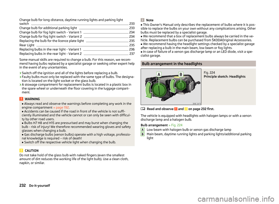
Bulb arrangement in the headlights
Fig. 224
Principle sketch: Headlights
Read and observe and on page 232 first.
The vehicle is equipped with headlights with halogen lamps or with a xenon
discharge lamp and a halogen bulb.
Bulb arrangement » Fig. 224
Low beam with halogen bulb or xenon gas discharge lamp
Main beam, daytime running lights and parking lights/additional parking
light
AB232Do-it-yourself