engine SKODA OCTAVIA 2014 3.G / (5E) Owner's Guide
[x] Cancel search | Manufacturer: SKODA, Model Year: 2014, Model line: OCTAVIA, Model: SKODA OCTAVIA 2014 3.G / (5E)Pages: 280, PDF Size: 35.53 MB
Page 119 of 280
Heating and air conditioning
Heating, ventilation, cooling
Introduction
This chapter contains information on the following subjects:
Air outlet vents
116
Air distribution control
117
Heating
118
Air conditioning (manual air conditioning)
119
Climatronic (automatic air conditioning)
119
Efficient handling of the cooling system
121
malfunctions
121
The heating and air conditioning ventilate and heat the vehicle interior. The air
conditioning system also cools and dehumidifies the vehicle interior.
The heating effect is dependent upon the coolant temperature, thus full heat
output only occurs when the engine has reached its operating temperature.
The cooling system operates only if the following conditions are met. The cooling system is switched on.
The engine is running.
The outside temperature is above approx. +2 °C.
The blower is switched on.
If the cooling system is switched on, the temperature and air humidity drops in
the vehicle. The cooling system prevents the windows from misting up during
the cold season of the year.
It is possible to briefly activate recirculated air mode to enhance the cooling
effect » page 117 .
WARNING■
For your own safety and that of other road users, ensure that all the win-
dows are free of ice, snow and misting.■
The blower should always be on to prevent the windows from misting up.
WARNING (Continued)■ Under certain circumstances, air at a temperature of about 5 °C can flow
out of the vents when the cooling system is switched on.■
To reduce health risks (e.g. common colds), the following instructions for
the use of the cooling system are to be observed. ■The difference between the indoor temperature and the outdoor air
temperature should not be greater than about 5 ° C.
■ The cooling system is to be turned off about 10 minutes before the end
of the journey.
■ Once a year, a disinfection of the air conditioner or the Climatronic is to
be carried out by a specialist company.
CAUTION
■ The air inlet in front of the windscreen must be free of e.g. ice, snow or
leaves to ensure that the heating and cooling system operates properly.■
After switching on the cooling Condensation from the evaporator of the air
conditioning may drip down and form a puddle below the vehicle. This is not a
leak!
■
If the coolant temperature is too high, the cooling system is switched off to
ensure that the engine cools down.
Note
The used air streams out through the vents in the luggage compartment.
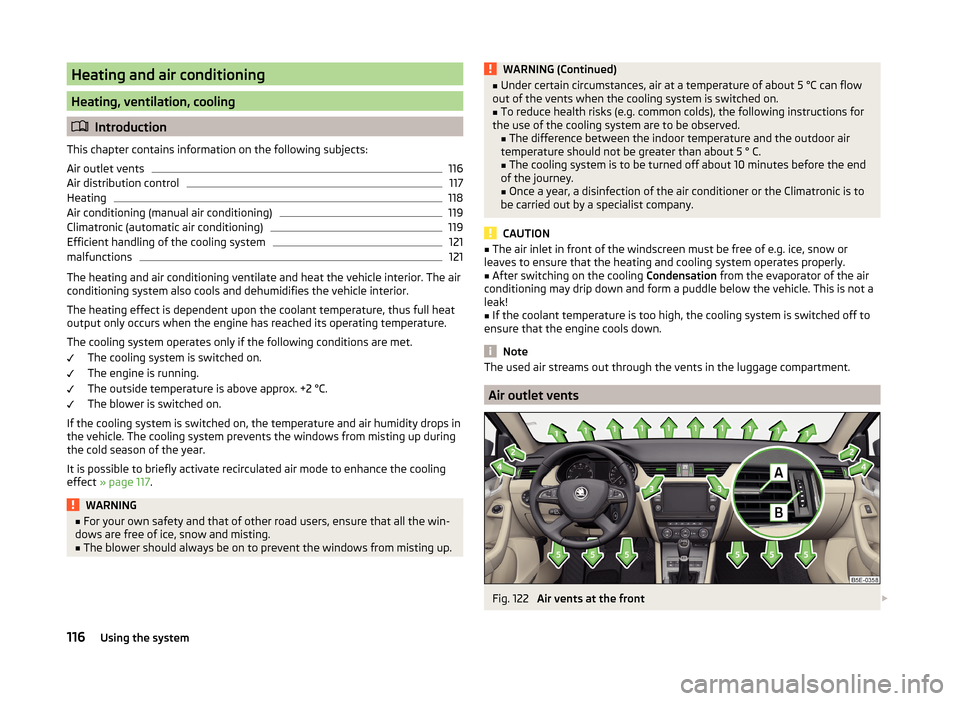
Air outlet vents
Fig. 122
Air vents at the front
116Using the system
Page 122 of 280
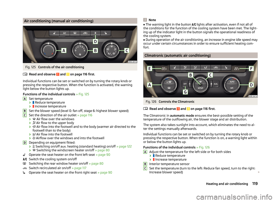
Air conditioning (manual air conditioning)Fig. 125
Controls of the air conditioning
Read and observe
and on page 116 first.
Individual functions can be set or switched on by turning the rotary knob or
pressing the respective button. When the function is activated, the warning
light below the button lights up.
Functions of the individual controls » Fig. 125
Set temperature ›
Reduce temperature
›
Increase temperature
Set the blower speed (level 0: fan off, stage 6: highest blower speed)
Set the direction of the air outlet » page 116
›
Air flow over the windows
›
Air flow to the upper body
›
Air flow into the footwell and to the body (warmer air directed to the
footwell than to the body)
›
Air flow into the footwell
›
Airflow over the windows and into the footwell
Depending on equipment fitted: ›
Switching on/off aux. heating (standard heating) on/off
» page 122
›
Switching the windscreen heater on/off
» page 80
Operate the seat heater on the front left seat » page 90
Switch the cooling system on/off
Switching the rear window heater on/off » page 80
Switch recirculated air on/off » page 117
Operate the seat heater on the front right seat » page 90
ABCDNote■
The warning light in the button lights after activation, even if not all of
the conditions for the function of the cooling system have been met. The light-
ing up of the indicator light in the button signals the operational readiness of
the cooling system.■
During operation of the air conditioning, an increase in engine idle speed may
occur under certain circumstances in order to ensure sufficient heating com-
fort.
Climatronic (automatic air conditioning)
Fig. 126
Controls the Climatronic
Read and observe
and on page 116 first.
The Climatronic in automatic mode ensures the best-possible setting of the
temperature of the outflowing air, the blower stage and air distribution.
The system also takes sunlight into account, which eliminates the need to al-
ter the settings manually afterwards.
Individual functions can be set or switched on by turning the rotary knob or
pressing the respective button. When the function is on, a warning light within
or below the button lights up.
Functions of the individual controls » Fig. 126
Adjust the temperature for the left side or for both sides
›
Reduce temperature
›
Increase temperature
Interior temperature sensor
Set the temperature (turn to the left: Reduce fan speed, turn to the right:
Increase blower speed)
ABC119Heating and air conditioning
Page 124 of 280
■As soon as the windscreen mists up, press the symbol button . Press the
button once the windscreen has demisted.■
During operation of the Climatronic, an increase in engine idle speed can oc-
cur under certain circumstances in order to ensure adequate heating comfort.
Efficient handling of the cooling system
Read and observe
and on page 116 first.
The air conditioning system compressor uses power from the engine when in
cooling mode, which will affect the fuel consumption.
It recommended to open the windows or the doors of a vehicle for which the
interior has been strongly heated through the effect of direct sunlight in order
to allow the heated air to escape.
The cooling system should not be on if the windows are open.
For the sake of the environment
Pollutant emissions are also lower when fuel is being saved » page 136.
malfunctions
Read and observe
and on page 116 first.
If the cooling system does not operate at outside temperatures higher than
+5 °C, there is a problem in the system. The reasons for this may be.
› One of the fuses has blown. Check the fuse and replace if necessa-
ry » page 229 .
› The cooling system has switched off automatically for a short time because
the coolant temperature of the engine is too hot » page 32.
If you are not able to resolve the operational problem yourself, or if the cooler
output has reduced, switch off the cooling system and seek assistance from a
specialist garage.
Auxiliary heating (auxiliary heating and ventilation)
Introduction
This chapter contains information on the following subjects:
Switching on/off
122
Radio remote control
123Conditions for the functioning of auxiliary heating (auxiliary heating and venti-
lation), hereinafter referred to only as auxiliary heating.
The charge state of the vehicle battery is sufficient.
The fuel supply is adequate (the warning icon
is not lit in the display of
the instrument cluster).
Auxiliary ventilation
The auxiliary ventilation enables fresh air to flow into the vehicle interior by
switching off the engine, whereby the interior temperature is effectively de-
creased (e.g. with the vehicle parked in the sun).
Auxiliary heating (parking heating)
The auxiliary heating can be used when both when stationary, when the en-
gine is switched off, to preheat the vehicle and also while driving (e.g. during
the heating phase of the engine).
The auxiliary heater functions in connection with the air-conditioning system
or Climatronic.
The auxiliary heating also warms up the engine.
The auxiliary heating warms up the coolant by combusting fuel from the vehi-
cle tank. This heats the air flowing into the passenger compartment (if the
blower is turned on).
The heater is switched on or off automatically depending on the ambient con-
ditions to give the best possible conditions for the engine running and the in-
terior heating.
The automatic switching on and off of the heater can be turned off by a spe-
cialist garage.WARNING■ The auxiliary heating must never be operated in closed rooms (e.g. garag-
es) – risk of poisoning!■
The auxiliary heating must not be allowed to run during refuelling – risk
of fire.
■
The exhaust pipe of the auxiliary heating is located on the underside of
the vehicle. If you want to use the heater, do not park the car in places
where the exhaust fumes can come into contact with flammable materials
such as dry grass, undergrowth, leaves, spilled fuel etc. - risk of fire.
121Heating and air conditioning
Page 125 of 280
CAUTION■The running auxiliary heater consumes fuel from the vehicle tank and auto-
matically controls the filling level. If only a low quantity of fuel is present in the
fuel tank, the auxiliary heating switches off.■
The exhaust pipe of the auxiliary heating, which is located on the underside
of the vehicle, must not be clogged and the exhaust flow must not be blocked.
■
If the auxiliary heating is running, the vehicle battery discharges. If the auxili-
ary heating and ventilation has been operated several times over a longer peri-
od, the vehicle must be driven a few kilometres in order to recharge the vehi-
cle battery.
■
The air inlet in front of the windscreen must be free (e.g. of ice, snow or
leaves) to ensure that the auxiliary heating operates properly.
Note
■ The auxiliary heating switches on the blower B » Fig. 125 on page 119 orC » Fig. 126 on page 119 only if it has achieved a coolant temperature of ap-
prox. 50 °C.■
At low outside temperatures, this can result in a formation of water vapour in
the area of the engine compartment. This is quite normal and is not an operat-
ing problem.
■
So that warm air can flow into the vehicle interior after switching on the aux-
iliary heating, you must maintain the comfort temperature normally selected
by you, leave the fan switched on and leave the air outlet vents in an open po-
sition. It is recommended to put the air flow in the position
or
.
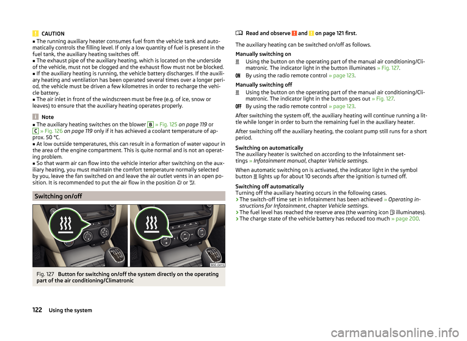
Switching on/off
Fig. 127
Button for switching on/off the system directly on the operating
part of the air conditioning/Climatronic
Read and observe and on page 121 first.
The auxiliary heating can be switched on/off as follows.
Manually switching on Using the button on the operating part of the manual air conditioning/Cli-
matronic. The indicator light in the button illuminates » Fig. 127.
By using the radio remote control » page 123.
Manually switching off Using the button on the operating part of the manual air conditioning/Cli-
matronic. The indicator light in the button goes out » Fig. 127.
By using the radio remote control » page 123.
After switching the system off, the auxiliary heating will continue running a lit- tle while longer in order to burn the remaining fuel in the auxiliary heater.
After switching off the auxiliary heating, the coolant pump still runs for a short
period.
Switching on automatically
The auxiliary heater is switched on according to the Infotainment set-
tings » Infotainment manual , chapter Vehicle settings .
When automatic switching on is activated, the indicator light in the symbol
button lights up for about 10 seconds after the ignition is turned off.
Switching off automatically
Turning off the auxiliary heating occurs in the following cases.
› The switch-off time set in Infotainment has been achieved
» Operating in-
structions for Infotainment , chapter Vehicle settings .
› The fuel level has reached the reserve area (the warning icon
illuminates).
› The charge state of the vehicle battery has reduced too much
» page 200.
122Using the system
Page 127 of 280

Communication
SmartGate
Introduction
This chapter contains information on the following subjects:
Connection with SmartGate
124
Smart Gate website
125
Password management
125
SmartGate is a system which transmits vehicle data via Wi-Fi.
The ŠKODA applications installed in a connected communications device (e.g.
phone, tablet, notebook) 1)
offer the possibility to further process the received
data.
Available applications and further information can be found on the ŠKODA
website.
WARNING■ The national legal regulations for using mobile communication devices in
a vehicle must be observed.■
Do not fit the equipment or fixtures onto airbag covers or within the im-
mediate deployment range of the airbags.
■
Never leave a connected device in the deployment area of an airbag, on a
seat, on the dash panel or any another area from where it can be thrown
during a sudden braking manoeuvre, an accident or a collision - risk of in-
jury.
Note
The Wi-Fi range is limited to the interior of the vehicle.
Connection with SmartGate
Read and observe
on page 124 first.
For a successful connection the following conditions must be met.
Wi-Fi is turned on in the device to be connected.
The ignition is switched on.
Connect›
Enable the connected device to search for available Wi-Fi networks (see op-
erating instructions for the connected device).
›
In the Found networks menu, select the connection to the
“SmartGate_ ... ”network 2)
.
›
Enter the password (the password is pre-set as the complete Vehicle Identi-
fication Number at the factory - enter in capital letters).
Disconnect the connection
The connection to SmartGate can be terminated in the following ways.
›
By disconnecting the connected device from SmartGate.
›
By turning off the Wi-Fi in the connected device.
›
By switching off the ignition and removing the key for more than 5 secs (for
vehicles with starter button, by turning off the engine and opening the driv-
er's door).
Automatic connection
The connection to SmartGate is automatically restored under the following
conditions.
Wi-Fi is turned on in the device to be connected.
The ignition is switched on.
The device to be connected has saved the password required for the con-
nection check.
Connection problems
If the connection fails, check the following points.
› Are the conditions for successful connection fulfilled?
› Is Smart Gate available in the list of available Wi-Fi networks?
› Has the password required for the connection check been entered?
› Is the password required for the connection check correct?
› Is the device to be connected still connected to another Wi-Fi network?
If the above items are ok but the connection still fails, contact a ŠKODA Part-
ner.
1)
The applications support communication devices with the Android operating system version 4.0.x and
higher, as well as iOS 7.xx and higher.
2)
The last six symbols of the VIN vehicle identification number of your vehicle are displayed at position ....
124Using the system
Page 129 of 280

Driving
Starting-off and Driving
Starting and stopping the engine using the key
Introduction
This chapter contains information on the following subjects:
Electronic immobilizer
126
Lock steering lock / unlock
126
Turning ignition on/off and starting the engine
127
Stopping the engine
127
With the key in the ignition, the ignition can be switched on and off and the
engine can be started / stopped.
WARNING■ While driving with the engine stopped, the ignition must always be
switched on » page 127, Turning ignition on/off and starting the engine .
■ With the ignition off, the steering may lock » page 126 - danger of an
accident!■
Do not withdraw the ignition key from the ignition lock until the vehicle
has come to a stop » page 132, Parking . Otherwise the steering wheel
could block – risk of accident!
■
Never leave the key in the vehicle when you exit the vehicle. Unauthor-
ized persons, such as children, for example, could lock the car, turn on the
ignition or start the engine - there is a danger of injury and accidents!
■
Never leave the vehicle unattended with the engine running - there is
risk of accident, damage or theft!
■
Never switch off the engine before the vehicle is stationary – risk of acci-
dent!
WARNING■ Never (e.g. in garages) run the engine in a closed place - there is the dan-
ger of poisoning and death!■
Do not leave any items (e.g. cloths or tools) in the engine compartment.
This presents a fire hazard and the risk of engine damage.
■
Never cover the engine with additional insulation material (e.g. with a
blanket) – risk of fire!
CAUTION■ Only start the engine when the engine and the vehicle are stationary - there
is a danger of starter and engine damage!■
Do not push-start the engine – there is a risk of damaging the engine and
the catalytic converter. The battery from another vehicle can be used as a
jump-start aid » page 220.
Note
Do not warm up the engine while the vehicle is stationary. If possible, start
your journey as soon as the engine has started. Through this, the engine rea-
ches its operating temperature faster.
Electronic immobilizer
Read and observe
and on page 126 first.
The electronic immobilizer makes a possible attempted theft or unauthorizeduse of your vehicle more difficult.
An electronic chip is integrated in the head of the key. The immobiliser is deac-
tivated with the aid of this chip when the key is inserted in the ignition lock.
The electronic immobiliser is automatically activated when the ignition key is
withdrawn from the lock.
The engine will not start if a non-authorized ignition key is used.
The following message is shown in the information cluster display. Immobilizer active.
IMMOBILIZER ACTIVE
Lock steering lock / unlock
Read and observe
and on page 126 first.
The steering lock (steering lock) deters any attempted theft of your vehicle.
Locking
›
Withdraw the ignition key.
›
Turn the steering wheel to the left or right until the steering lock clicks into
place.
Unlocking
›
Insert the key into the ignition lock.
›
Switch on the ignition » page 127.
126Driving
Page 130 of 280
The vehicle is unlocked.
If the ignition switch can not be turned on, then turn the steering wheel back
and forth slightly and thereby unlock the steering lock.
Turning ignition on/off and starting the engine
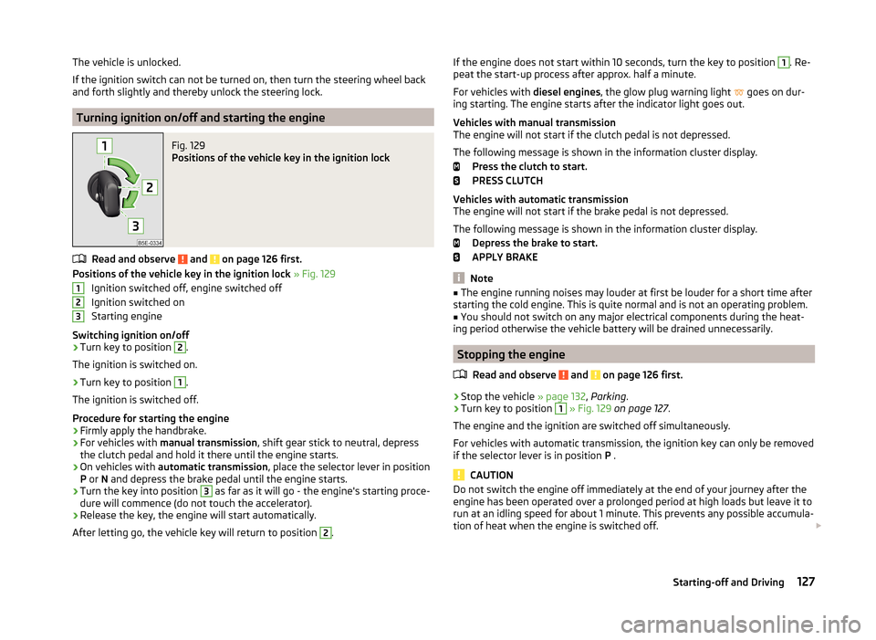
Fig. 129
Positions of the vehicle key in the ignition lock
Read and observe and on page 126 first.
Positions of the vehicle key in the ignition lock » Fig. 129
Ignition switched off, engine switched off
Ignition switched on
Starting engine
Switching ignition on/off
›
Turn key to position
2
.
The ignition is switched on.
›
Turn key to position
1
.
The ignition is switched off.
Procedure for starting the engine
›
Firmly apply the handbrake.
›
For vehicles with manual transmission , shift gear stick to neutral, depress
the clutch pedal and hold it there until the engine starts.
›
On vehicles with automatic transmission , place the selector lever in position
P or N and depress the brake pedal until the engine starts.
›
Turn the key into position
3
as far as it will go - the engine's starting proce-
dure will commence (do not touch the accelerator).
›
Release the key, the engine will start automatically.
After letting go, the vehicle key will return to position
2
.
123If the engine does not start within 10 seconds, turn the key to position 1. Re-
peat the start-up process after approx. half a minute.
For vehicles with diesel engines, the glow plug warning light
goes on dur-
ing starting. The engine starts after the indicator light goes out.
Vehicles with manual transmission
The engine will not start if the clutch pedal is not depressed.
The following message is shown in the information cluster display. Press the clutch to start.
PRESS CLUTCH
Vehicles with automatic transmission
The engine will not start if the brake pedal is not depressed.
The following message is shown in the information cluster display. Depress the brake to start.
APPLY BRAKE
Note
■ The engine running noises may louder at first be louder for a short time after
starting the cold engine. This is quite normal and is not an operating problem.■
You should not switch on any major electrical components during the heat-
ing period otherwise the vehicle battery will be drained unnecessarily.
Stopping the engine
Read and observe
and on page 126 first.
›
Stop the vehicle » page 132, Parking .
›
Turn key to position
1
» Fig. 129 on page 127 .
The engine and the ignition are switched off simultaneously.
For vehicles with automatic transmission, the ignition key can only be removed if the selector lever is in position P .
CAUTION
Do not switch the engine off immediately at the end of your journey after the
engine has been operated over a prolonged period at high loads but leave it to
run at an idling speed for about 1 minute. This prevents any possible accumula-
tion of heat when the engine is switched off. 127Starting-off and Driving
Page 131 of 280

NoteAfter switching off the ignition, the radiator fan may intermittently continue to
operate for approx. 10 minutes.
Starting or stopping the engine by pressing button
Introduction
Fig. 130
Starter button (
)
This chapter contains information on the following subjects:
Locking/unlocking the steering lock
128
Switching ignition on / off
129
Starting the engine
129
Switching off the engine
129
Problems starting the engine
130
The ignition can be switched on and off and the engine can be started/stop-
ped with the starter button » Fig. 130.
The key must be in the vehicle in order to unlock the steering wheel, switch on the ignition, start the engine and drive.
WARNING■ Never leave the key in the vehicle when you exit the vehicle. Unauthor-
ized persons, such as children, for example, could lock the car, turn on the
ignition or start the engine - there is a danger of injury and accidents!■
Never leave the vehicle unattended with the engine running - there is a
risk of theft etc!
■
Never switch off the engine before the vehicle is stationary – risk of acci-
dent!
WARNINGNever (e.g. in garages) run the engine in a closed place - there is the danger
of poisoning and death!
CAUTION
■ The system can recognize the valid key, even if it has been accidentally left
on the vehicle roof - there is danger of loss or damage to the key!■
Only start the engine when the engine and the vehicle are stationary - there
is a danger of starter and engine damage!
■
Do not push-start the engine – there is a risk of damaging the engine and
the catalytic converter. The battery from another vehicle can be used as a
jump-start aid » page 220.
Note
■
Do not warm up the engine while the vehicle is stationary. If possible, start
your journey as soon as the engine has started. Through this, the engine rea-
ches its operating temperature faster.■
The system is protected against inadvertently switching off the engine while
driving, this means that the engine can only be switched off in an emergen-
cy » page 129 .
Locking/unlocking the steering lock
Read and observe
and on page 128 first.
The steering lock (steering lock) deters any attempted theft of your vehicle.
Locking
›
Switch off the engine.
›
Open the driver door.
The steering lock is locked automatically.
If the driver's door is opened and the ignition is switched off afterwards, the
steering is only locked after the vehicle has been locked.
Unlocking
›
Open the driver's door and get into the vehicle.
›
Close the driver's door.
The steering is locked automatically.
128Driving
Page 132 of 280
Under certain circumstances (e.g. after switching off the ignition and opening
the driver's door), the steering is enabled only when the ignition is switched on
or the engine is started.WARNINGNever let the vehicle roll with locked steering lock - there is a risk of acci-
dent!
Switching ignition on / off
Read and observe
and on page 128 first.
›
Press the button » Fig. 130 on page 128 briefly.
The ignition is switched on or off.
On vehicles fitted with a manual gearbox, the clutch pedal must not be de-
pressed while switching the ignition on or off, otherwise the system would try
to start.
On vehicles fitted with a automatic gearbox, the brake pedal must not be de-
pressed while switching the ignition on or off, otherwise the system would try
to start.
If the driver's door is opened while the igition is on, an audible signal sounds
and the following message appears in the instrument cluster display.
Ignition on!
IGNITION STILL ON
When leaving the vehicle always switch off the ignition.
Starting the engine
Read and observe
and on page 128 first.
Procedure for starting the engine
›
Firmly apply the handbrake.
›
For vehicles with manual transmission , shift gear stick to neutral, depress
the clutch pedal and hold it there until the engine starts.
›
On vehicles with automatic transmission , place the selector lever in position
P or N and depress the brake pedal until the engine starts.
›
Press the starter button » Fig. 130 on page 128 briefly – the engine starts au-
tomatically.
In vehicles with diesel engines after pressing the button, the glow plug warn-
ing light lights up. The engine can be started after the indicator light goes
out.
Note
■ The engine running noises may louder at first be louder for a short time after
starting the cold engine. This is quite normal and is not an operating problem.■
You should not switch on any major electrical components during the heat-
ing period otherwise the vehicle battery will be drained unnecessarily.
Switching off the engine
Read and observe
and on page 128 first.
Switching off
›
Stop the vehicle » page 132, Parking .
›
Press the button » Fig. 130 on page 128 briefly.
The engine and the ignition are switched off simultaneously.
Emergency shutdown
If necessary, the engine in exceptional cases may also be turned off while driv-
ing.
›
Press the starter button » Fig. 130 on page 128 for longer than 1 second or
twice within 1 second.
After the emergency stop of the engine, the steering lock will remain un-
locked.
CAUTION
Do not switch the engine off immediately at the end of your journey after the
engine has been operated over a prolonged period at high loads but leave it to
run at an idling speed for about 1 minute. This prevents any possible accumula-
tion of heat when the engine is switched off.
Note
After switching off the ignition, the radiator fan may intermittently continue to
operate for approx. 10 minutes.129Starting-off and Driving
Page 133 of 280
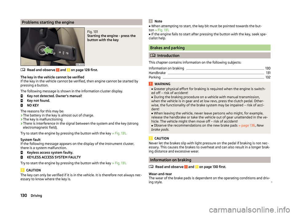
Problems starting the engineFig. 131
Starting the engine - press the
button with the key
Read and observe and on page 128 first.
The key in the vehicle cannot be verified
If the key in the vehicle cannot be verified, then engine cannot be started by pressing a button.
The following message is shown in the information cluster display. Key not detected. Owner's manual!
Key not found.
NO KEY
The reasons for this may be:
› The battery in the key is almost out of charge.
› The key is malfunctioning
› There is interference in the signal between the system and the key (strong
electromagnetic field).
Try to start the engine by pressing the button with the key » Fig. 131.
System fault
If the following message appears on the display of the instrument cluster,
there is a system malfunction.
Keyless access system faulty.
KEYLESS ACCESS SYSTEM FAULTY
Try to start the engine by pressing the button with the key » Fig. 131.
CAUTION
The key can only be verified if it is in the vehicle. It is therefore not always nec-
essary to know where the key is.Note■ When attempting to start, the key bit must be pointed towards the but-
ton » Fig. 131 .■
If the engine fails to start after pressing the button with the key, seek spe-
cialist help.
Brakes and parking
Introduction
This chapter contains information on the following subjects:
Information on braking
130
Handbrake
131
Parking
132WARNING■ Greater physical effort for braking is required when the engine is switch-
ed off – risk of accident!■
During the braking procedure on a vehicle with manual transmission,
when the vehicle is in gear and at low revs, press the clutch pedal. Other-
wise, the functionality of the brake system may be impaired – risk of acci-
dent!
■
When leaving the vehicle, never leave persons who might, for example,
release the handbrake or take the vehicle out of gear unattended in the ve-
hicle. The vehicle might then move off – risk of accident!
■
Observe the recommendations on the new brake pads » page 136, New
brake pads .
CAUTION
Never let the brakes slip with light pressure on the pedal if braking is not nec-
essary. This causes the brakes to overheat and can also result in a longer brak-
ing distance and excessive wear.
Information on braking
Read and observe
and on page 130 first.
Wear-and-tear
The wear of the brake pads is dependent on the operating conditions and driv-
ing style.
130Driving