stop start SKODA OCTAVIA 2014 3.G / (5E) Owner's Guide
[x] Cancel search | Manufacturer: SKODA, Model Year: 2014, Model line: OCTAVIA, Model: SKODA OCTAVIA 2014 3.G / (5E)Pages: 280, PDF Size: 35.53 MB
Page 162 of 280

›Release the clutch pedal.
Automatic engine shutdown then occurs and the indicator symbol appears in
the display
» Fig. 156 on page 158 .
Automatic engine start›
Depress the clutch pedal.
The automatic re-start process takes place and the indicator symbol
goes
out.
Operation in vehicles with automatic gearbox
Read and observe
on page 158 first.
In compliance with the operating conditions, automatic engine shutdown / au-
tomatic engine start takes place as described.
Automatic engine shutdown
›
Bring the vehicle to a stop and depress the brake pedal.
Automatic engine shutdown then occurs and the indicator symbol appears in
the display
» Fig. 156 on page 158 .
Automatic engine start
›
Release the brake pedal.
The automatic re-start process takes place and the indicator symbol goes
out.
Further information on automatic transmission
Engine shut down takes place when the selector lever is in positions P, D/S , N
and in Tiptronic mode.
When the selector lever is in position P the engine remains shut down after
you release the brake pedal. The engine starts automatically by pressing the
gas pedal or by moving the selector lever into a different mode and releasing
the brake pedal.
If the engine is off due to the automatic and the selector lever is put to the R
position then the automatic starts the engine.
If the gear selector is moved from position R to the position D/S or N the vehi-
cle must reach a speed of more than 10 km / h before the automatic engine
shutdown starts.
There is no automatic engine shutdown when the system detects a vehicle
moving due to a large steering angle.
No automatic engine shutdown takes place when the vehicle is moving at low
speed (e.g. during a traffic jam or when tuning) and remains stationary after
pressing the brake pedal lightly. Automatic engine shutdown takes place if you
press the brake pedal down with more force.
System related automatic start-up
Read and observe
on page 158 first.
When the engine is off, the system can automatically start the engine beforethe desired journey continues. Some possible reasons for this are:
› The vehicle begins to roll, e.g. on a slope.
› The brake pedal has been actuated several times.
› The current consumption is too high.
Manually deactivating/activating the system
Fig. 157
Button for the START-STOP sys-
tem
Read and observe on page 158 first.
Deactivating/activating
›
Press the symbol button
» Fig. 157 .
When start-stop mode is deactivated, the warning light in the button lights up.
Note
■ If the system is deactivated when the engine is turned off automatically,
then the automatic start process takes place.■
Selecting the driving mode Eco when the system is deactivated will automat-
ically activate the system » page 160, Selection of travel mode (Driving Mode
Selection) .
159Assist systems
Page 163 of 280

Information messagesRead and observe
on page 158 first.
The information messages are shown in the instrument cluster display. Start the engine manually!
START MANUALLY
One of the conditions for automatic engine start is not satisfied or the driver's
seat belt is not fastened. The engine must be started manually.
On vehicles with the starter button, the ignition is turned off by the first press of the starter button; the start process is only initiated when the button is
pressed for the second time.
Error: start-stop system
START STOP ERROR
A system error is present. Seek help from a specialist garage.
Selection of travel mode (Driving Mode Selection)
Introduction
This chapter contains information on the following subjects:
Selection
160
Normal Mode
160
Sportmode
160
Ecomode
161
Individualmode
161
By selecting the driving mode, the driving behavior can be adapted to the de-
sired mode of operation.
The following modes of Normal, Sport, Eco, Individual are available.
The set driving mode remains stored even after switching the ignition on and
off.
WARNING■ The system only serves to support and does not relieve the driver of the
responsibility for the vehicle operation.■
Adjust the speed and driving style to the current visibility, weather, road
and traffic conditions.
SelectionFig. 158
Button for selecting the driving mode: Version 1/version 2
Read and observe
on page 160 first.
›
Press the symbol button or
» Fig. 158 .
The menu is displayed on the infotainment screen.
The mode is changed by repeatedly pressing the symbol button or
or in
the Infotainment display » Infotainment operating instructions , chapter Vehi-
cle settings .
If a driving mode other than Normal is selected, then the symbol lights up on
the button or
» Fig. 158 .
WARNINGSetting the driving mode while driving can distract you from other traffic –
risk of accident.
Normal Mode
Read and observe
on page 160 first.
This mode is suitable for common everyday use.
SportmodeRead and observe
on page 160 first.
This mode is suitable for a sporty driving style.
Selecting this mode primarily affects the function of the following systems.
160Driving
Page 164 of 280

Engine (drive)
The vehicle acceleration is more dynamic than in Normal mode.
The engine noise is noticeable in the interior more intensely than in
normalmode 1)
.
Steering
The power steering is reduced slightly, i.e., the driver needs to exert more
force for steering .
Adaptive Cruise Control (ACC)
The acceleration is quicker than in normal mode with distance con-
trol » page 149 .
Adaptive headlights (AHL)
The headlights adapt to the driving style more dynamically than in mode
Normal » page 74 .
ProActive passenger protection
The first level of protection is deactivated » page 161.
Ecomode
Read and observe
on page 160 first.
This mode is suitable for a relaxed style of driving and helps to save fuel.
Selecting this mode primarily affects the function of the following systems.
Engine (drive)
Vehicle acceleration is more relaxed than in Normal mode.
The recommended gear is controlled such to achieve the lowest possible fuel
consumption » page 46.
When the START-STOP system was deactivated manually » page 158, it is au-
tomatically activated.
The automatic gearbox is set automatically to mode E » page 133 .
The engine noise is felt less intensely in the interior less than in normalmode 1)
.
Adaptive Cruise Control (ACC)
Acceleration occurs more relaxed than in Normal » page 149mode with dis-
tance control.
Adaptive headlights (AHL)
The system is automatically deactivated » page 74.
Air conditioning (Climatronic)
The air conditioning is controlled so as to save energy. For this reason, for ex-
ample, it may take longer to reach the desired interior temperature in mode
Normal.
Note
■ The Eco driving mode is not available when towing a trailer. When the vehicle
is connected electrically to a trailer and is in the Eco driving mode, the Normal
driving mode is configured automatically.■
The maximum vehicle acceleration (kickdown function) is possible also in
driving mode Eco.
Individualmode
Read and observe
on page 160 first.
In mode Individual you can select between Normal, Sport and Eco for each sys-tem separately » Operating instructions for Infotainment , chapter Vehicle set-
tings .
ProActive passenger protection
Introduction
This chapter contains information on the following subjects:
Function
162
ProActive passenger protection (From here on referred to only as system) in-
creases passenger protection in the front seats in situations that could lead to
vehicle impact or overturning.
WARNING■ The increased safety by ProActive passenger protection must not tempt
you to take greater risks than otherwise – risk of accident!■
Adjust the speed and driving style to the current visibility, weather, road
and traffic conditions.
1)
Applies to Octavia RS, Octavia RS.
161Assist systems
Page 194 of 280
CAUTION■Just filling the tank once with diesel fuel that does not comply with the
standard, can cause severe damage to parts of the engine, the fuel and ex-
haust system!■
If a different fuel other than diesel fuel, which complies to the above men-
tioned standards (e.g. petrol) is used, do not start the engine or switch on the
ignition! Extensive damage to engine parts can occur!
■
Water which has collected in the fuel filter can cause engine faults.
CAUTION
■ The vehicle cannot be operated with bio fuel RME, therefore this fuel must
not be filled in the tank and used for driving the vehicle. The use of biofuel
RME can cause considerable damage to parts of the engine or fuel system.■
Do not mix any fuel additives, so-called “flow improvers” (petrol and similar
agents) into the diesel. This can result in considerable damage to parts of the
engine or the exhaust system.
Refuelling with CNG (compressed natural gas)
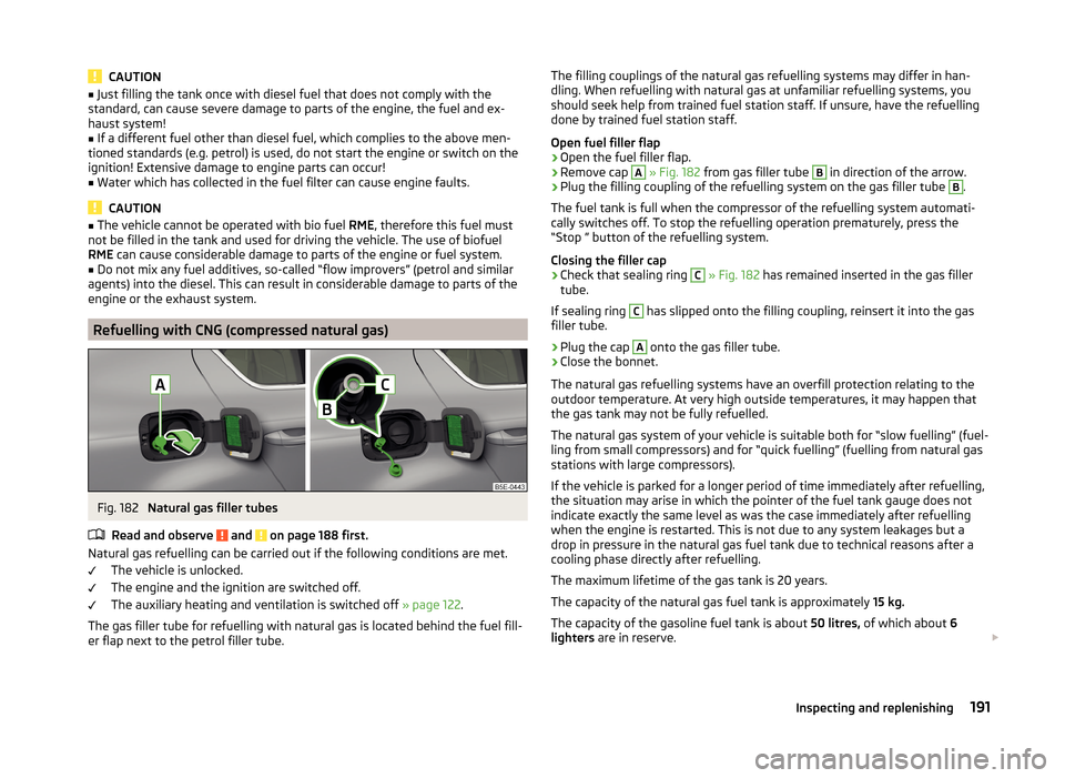
Fig. 182
Natural gas filler tubes
Read and observe
and on page 188 first.
Natural gas refuelling can be carried out if the following conditions are met. The vehicle is unlocked.
The engine and the ignition are switched off.
The auxiliary heating and ventilation is switched off » page 122.
The gas filler tube for refuelling with natural gas is located behind the fuel fill- er flap next to the petrol filler tube.
The filling couplings of the natural gas refuelling systems may differ in han-
dling. When refuelling with natural gas at unfamiliar refuelling systems, you
should seek help from trained fuel station staff. If unsure, have the refuelling done by trained fuel station staff.
Open fuel filler flap›
Open the fuel filler flap.
›
Remove cap
A
» Fig. 182 from gas filler tube
B
in direction of the arrow.
›
Plug the filling coupling of the refuelling system on the gas filler tube
B
.
The fuel tank is full when the compressor of the refuelling system automati-
cally switches off. To stop the refuelling operation prematurely, press the
“Stop ” button of the refuelling system.
Closing the filler cap
›
Check that sealing ring
C
» Fig. 182 has remained inserted in the gas filler
tube.
If sealing ring
C
has slipped onto the filling coupling, reinsert it into the gas
filler tube.
›
Plug the cap
A
onto the gas filler tube.
›
Close the bonnet.
The natural gas refuelling systems have an overfill protection relating to the
outdoor temperature. At very high outside temperatures, it may happen that
the gas tank may not be fully refuelled.
The natural gas system of your vehicle is suitable both for “slow fuelling” (fuel-
ling from small compressors) and for “quick fuelling” (fuelling from natural gas
stations with large compressors).
If the vehicle is parked for a longer period of time immediately after refuelling,
the situation may arise in which the pointer of the fuel tank gauge does not
indicate exactly the same level as was the case immediately after refuelling
when the engine is restarted. This is not due to any system leakages but a
drop in pressure in the natural gas fuel tank due to technical reasons after a
cooling phase directly after refuelling.
The maximum lifetime of the gas tank is 20 years.
The capacity of the natural gas fuel tank is approximately 15 kg.
The capacity of the gasoline fuel tank is about 50 litres, of which about 6
lighters are in reserve.
191Inspecting and replenishing
Page 196 of 280
WARNINGWhen working in the engine compartment, injuries, scolding, accident or
fire hazards may arise. For this reason, it is essential to comply with the
warning instructions stated below and with the general applicable rules of
safety. The engine compartment of your car is a hazardous area!WARNINGInstructions before beginning work in the engine compartment■Turn off the engine and withdraw the ignition key.■
Firmly apply the handbrake.
■
For vehicles with manual transmission the lever into the neutral position.
■
On vehicles with automatic transmission, shift the selector lever into the
P position.
■
Allow the engine to cool.
■
Never open the bonnet if you can see steam or coolant flowing out of the
engine compartment – risk of scalding! Wait until the steam or coolant has
stopped escaping.
WARNINGInformation for working in the engine compartment■Keep all people, especially children, away from the engine compartment.■
Never touch the radiator fan while the engine is still warm. The fan might
suddenly start running!
■
Do not touch any hot engine parts – risk of burns!
WARNINGInformation for working in the engine compartment with the engine run-
ning■
Pay particular attention to moving engine parts, e.g. V-ribbed belt, gener-
ator, radiator fan - danger to life!
■
Never touch the electric wiring on the ignition system.
■
Avoid short circuits in the electrical system – particularly on the vehicle's
battery.
■
Always make sure that no jewellery, loose clothing or long hair can get
caught in rotating engine parts – risk of death! Always remove any jewel-
lery, tie back long hair and wear tight fitting clothing before completing any
work.
WARNINGInformation for working on the fuel system or the electrical system■Always disconnect the vehicle battery from the electrical system.■
Do not smoke.
■
Never work near open flames.
■
Always have a functioning fire extinguisher nearby.
WARNING■ Read the information and warning instructions on the fluid containers.■Keep the working fluids in sealed original containers and safe from peo-
ple who are not completely independent, e.g. children.■
Never spill fluids over the hot engine - risk of fire.
■
If you wish to work under the vehicle, you must secure the vehicle from
rolling away and support it with suitable supporting blocks: the car jack is
not sufficient for this – risk of injury!
CAUTION
Always top up using the correct specification of fluids. This may result in major
operating problems and also vehicle damage!
For the sake of the environment
In view of the requirements for the environmentally friendly disposal of fluids and the special tools and knowledge required for such work, we recommend
that fluids be changed by a specialist garage.
Note
■ Please consult a specialist garage for any questions relating to fluids.■Fluids with the proper specifications can be purchased from the ŠKODA Origi-
nal Accessories or from the ŠKODA Genuine Parts ranges.193Inspecting and replenishing
Page 204 of 280

■Do not place the battery in direct daylight in order to protect the vehicle bat-
tery housing from the effects of ultra-violet light.■
If the vehicle is frequently used for making short trips, the vehicle battery
will not have time to charge up sufficiently and may discharge.
For the sake of the environment
A vehicle battery that has been removed is a special type of hazardous waste.
These must be disposed of in accordance with national legal regulations.
Note
■ We recommend having all work on the vehicle battery carried out by a spe-
cialist garage.■
You should replace batteries older than 5 years.
Opening the cover
Fig. 190
Polyester cover of vehicle bat-
tery
Read and observe and on page 200 first.
The battery is located in the engine compartment. For some equipment var-
iants, it is located underneath a polyester cover » Fig. 190.
›
Fold out the cover on the battery in the direction of the arrow.
The battery cover is installed in reverse order.
Checking the battery electrolyte levelFig. 191
Vehicle battery: Electrolyte level
indicator
Read and observe and on page 200 first.
On vehicles with a vehicle battery fitted with a colour indicator » Fig. 191, the
electrolyte level can be determined by looking at the change in colour of this
display.
Air bubbles can influence the colour of the indicator. For this reason carefully
knock on the indicator before carrying out the check.
› Black colour – electrolyte level is correct.
› Colourless or light yellow colour – electrolyte level too low, the battery must
be replaced.
Vehicles with a START-STOP system are fitted with a battery control unit for
checking the energy level for the recurring engine start.
We recommend that you have the acid level checked regularly by a specialist
garage, especially in the following cases.
› High external temperatures.
› Longer day trips.
› After each charge.
Winter time
The vehicle battery only has a proportion of the starting power in lower tem-
peratures. A discharged vehicle battery may already freeze at temperatures
just below 0 °C .
We therefore recommend that you have the battery checked and, if necessary,
recharged by a specialist garage before the start of the winter.
201Inspecting and replenishing
Page 205 of 280
Note■The battery acid level is also checked regularly by a specialist garage as part
of the inspection service.■
For technical reasons, on vehicles with the description “AGM”, the electrolyte
level cannot be checked.
Charging
Read and observe
and on page 200 first.
A properly charged vehicle battery is essential for reliably starting the engine.
A charging operation can be performed if the following conditions are satis-
fied.
The engine is turned off.
The ignition is switched off.
All consumers are turned off.
The bonnet is open.
“Fast charging” with high currents
›
Disconnect both battery cables (first of all “negative”, then “positive”).
›
Attach the terminal clamps of the charger to the battery terminals (red =
“positive”, black = “negative”).
›
Plug the mains cable of the charger into the power socket and switch on the
device.
›
After charging has been successful: Switch off the charger and remove the
mains cable from the power socket.
›
Only then disconnect the charger's terminal clamps.
›
Reconnect the cables to the battery (first of all “positive”, then “negative”).
Charging with low voltages
It is not necessary to disconnect the cables from the battery if you recharge
the vehicle battery, for example from a mini-charger.
Refer to the instructions of the charger manufacturer .
A charging current of 0.1 multiple of the total vehicle battery capacity (or low-
er) must be used until full charging is achieved.
The vent plugs of the vehicle battery should not be opened for charging.
WARNING■ When you charge a battery, hydrogen is released, and a highly explosive
gas mixture is also produced. An explosion can be caused through sparkling
over during unclamping or loosening of the cable plug while the ignition is
on.■
Creating a bridge between the poles on the battery (e.g. with metal ob-
jects - cables) creates a short circuit - risk of damage to the battery, explo-
sion and burning of the battery, jets of acid spurting out.
■
Avoid creating sparks when working with cables and electrical devices.
Strong sparking represents a risk of injury.
■
Before carrying out any work on the electrical system, switch off the en-
gine, the ignition and all electrical components and disconnect the negative
terminal
.
■
“Quick-charging” the vehicle battery is dangerous and requires a special
charger and specialist knowledge.
■
We therefore recommend that vehicle batteries be “rapidly charged” by a
specialist garage.
CAUTION
On vehicles with the START/STOP system or additional heating (auxiliary heat-
ing), do not connect the pole terminal of the charger directly to the negative
terminal of the vehicle battery, but rather only to the engine earth » page 220,
Jump-starting using the battery from another vehicle .
Replacing
Read and observe
and on page 200 first.
The new vehicle battery must have the same capacity, voltage, current and
size as the original battery. Suitable vehicle battery types can be purchased
from a specialist garage.
We recommend having the battery replaced by a specialist garage, where the
new vehicle battery will be installed properly and the original battery will be
disposed of in accordance with national regulations.
Disconnecting and reconnecting
Read and observe
and on page 200 first.
Disconnecting
›
Switch off the ignition.
202General Maintenance
Page 220 of 280
Their positions are indicated by embossed markings B in the side of the lower
beam.
Raising the vehicle›
Insert the crank
7
into the mount on the jack
6
» page 212 .
›
Support the base plate of the jack with its entire surface resting on level
ground and ensure that the lever is positioned vertically to the jacking
point » Fig. 202 .
›
Use the crank to raise the jack until its claw encloses the bar » Fig. 202.
›
Continue to raise the jack until the wheel is just lifted off the ground.
WARNING■
Choose a flat and firm surface for jacking the vehicle.■If the wheel has to be changed on a slope, first of all block the opposite
wheel with a stone or similar object to prevent the vehicle from unexpect-
edly rolling away.■
Secure the base plate of the lifting jack with suitable means to prevent
possible moving. A soft and slippery ground under the base plate may move
the lifting jack, causing the vehicle to fall down. It is therefore always nec-
essary to place the lifting jack on a solid surface or use a wide and stable
base. Use a non-slip base (e.g. a rubber foot mat) if the surface is smooth,
such as cobbled stones, tiled floor, etc.
■
Only attach the lifting jack to the attachment points provided for this pur-
pose.
■
Always raise the vehicle with the doors closed.
■
Never position any body parts, such as arms or legs under the vehicle,
while the vehicle is raised with a lifting jack.
■
When the vehicle is raised, never start the engine.
CAUTION
It is important to ensure that the jack is correctly attached to the bar of the
lower beam, as otherwise there is a risk of damage to the vehicle.Anti-theft wheel boltsFig. 203
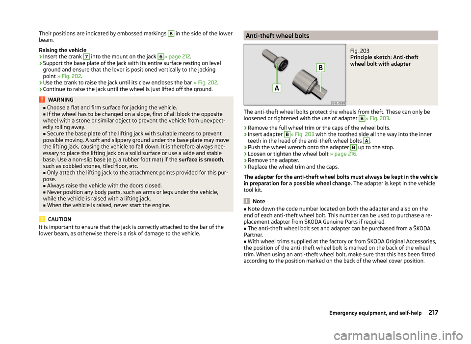
Principle sketch: Anti-theft
wheel bolt with adapter
The anti-theft wheel bolts protect the wheels from theft. These can only be
loosened or tightened with the use of adapter
B
» Fig. 203 .
›
Remove the full wheel trim or the caps of the wheel bolts.
›
Insert adapter
B
» Fig. 203 with the toothed side all the way into the inner
teeth in the head of the anti-theft wheel bolts
A
.
›
Push the wheel wrench onto the adapter
B
up to the stop.
›
Loosen or tighten the wheel bolt » page 216.
›
Remove the adapter.
›
Replace the wheel trim and the caps.
The adapter for the anti-theft wheel bolts must always be kept in the vehicle
in preparation for a possible wheel change. The adapter is kept in the vehicle
tool kit.
Note
■ Note down the code number located on both the adapter and also on the
end of each anti-theft wheel bolt. This number can be used to purchase a re-
placement adapter from ŠKODA Genuine Parts if required.■
The anti-theft wheel bolt set and adapter can be purchased from a ŠKODA
Partner.
■
With wheel trims supplied at the factory or from ŠKODA Original Accessories,
the position of the anti-theft wheel bolt is marked on the back of the wheel
trim. When using an anti-theft wheel bolt, make sure that this has been fitted
according to the position marked on the back of the wheel cover position.
217Emergency equipment, and self-help
Page 224 of 280
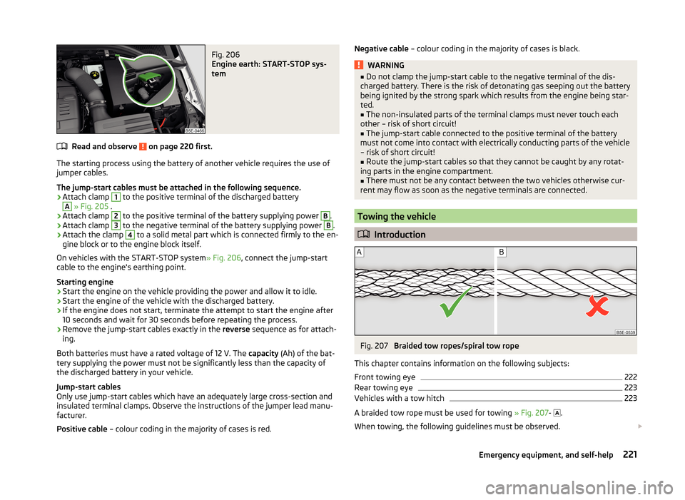
Fig. 206
Engine earth: START-STOP sys-
tem
Read and observe on page 220 first.
The starting process using the battery of another vehicle requires the use of
jumper cables.
The jump-start cables must be attached in the following sequence.
›
Attach clamp
1
to the positive terminal of the discharged battery
A
» Fig. 205 .
›
Attach clamp
2
to the positive terminal of the battery supplying power
B
.
›
Attach clamp
3
to the negative terminal of the battery supplying power
B
.
›
Attach the clamp
4
to a solid metal part which is connected firmly to the en-
gine block or to the engine block itself.
On vehicles with the START-STOP system » Fig. 206, connect the jump-start
cable to the engine's earthing point.
Starting engine
›
Start the engine on the vehicle providing the power and allow it to idle.
›
Start the engine of the vehicle with the discharged battery.
›
If the engine does not start, terminate the attempt to start the engine after
10 seconds and wait for 30 seconds before repeating the process.
›
Remove the jump-start cables exactly in the reverse sequence as for attach-
ing.
Both batteries must have a rated voltage of 12 V. The capacity (Ah) of the bat-
tery supplying the power must not be significantly less than the capacity of
the discharged battery in your vehicle.
Jump-start cables
Only use jump-start cables which have an adequately large cross-section and
insulated terminal clamps. Observe the instructions of the jumper lead manu-
facturer.
Positive cable – colour coding in the majority of cases is red.
Negative cable – colour coding in the majority of cases is black.WARNING■
Do not clamp the jump-start cable to the negative terminal of the dis-
charged battery. There is the risk of detonating gas seeping out the battery being ignited by the strong spark which results from the engine being star-
ted.■
The non-insulated parts of the terminal clamps must never touch each
other – risk of short circuit!
■
The jump-start cable connected to the positive terminal of the battery
must not come into contact with electrically conducting parts of the vehicle
– risk of short circuit!
■
Route the jump-start cables so that they cannot be caught by any rotat-
ing parts in the engine compartment.
■
There must not be any contact between the two vehicles otherwise cur-
rent may flow as soon as the negative terminals are connected.
Towing the vehicle
Introduction
Fig. 207
Braided tow ropes/spiral tow rope
This chapter contains information on the following subjects:
Front towing eye
222
Rear towing eye
223
Vehicles with a tow hitch
223
A braided tow rope must be used for towing » Fig. 207-
.
When towing, the following guidelines must be observed.
221Emergency equipment, and self-help
Page 226 of 280

›After unscrewing the towing eye, insert the cap in the area of arrow 1 and
then press the opposite side of the cap.
The cap must engage firmly.
Removing/installing the towing eye›
Manually screw the towing eye as far as it will go in the direction of the ar-
row
3
» Fig. 208 » .
For tightening purposes, we recommend, for example, using the wheel
wrench, towing eye from another vehicle or a similar object that can be pushed through the eye.
›
Unscrew the towing eye against the direction of the arrow
3
.
WARNINGThe towing eye must always be screwed in fully and firmly tightened, oth-
erwise the towing eye can tear when towing in or tow-starting.
Rear towing eye
Fig. 209
Expansion of the cap / installation of towing eye - Version 1
Fig. 210
Expansion of the cap / installation of towing eye - Version 2
Read and observe
and on page 222 first.
Removing/installing the cap
›
Press on the cap in the area of arrow
1
» Fig. 209 or » Fig. 210 .
›
Remove the cap in the direction of arrow
2
.
›
After unscrewing the towing eye, insert the cap in the area of arrow
1
.
›
Press the opposite side of the cap.
The cap must engage firmly.
Removing/installing the towing eye
›
Manually screw the towing eye in as far as it will go in the direction of the
arrow
3
» Fig. 209 or » Fig. 210 to the stop » .
For tightening purposes, we recommend, for example, using the wheel
wrench, towing eye from another vehicle or a similar object that can be pushed through the eye.
›
Unscrew the towing eye against the direction of the arrow
3
.
WARNINGThe towing eye must always be screwed in fully and firmly tightened, oth-
erwise the towing eye can tear when towing in or tow-starting.
Vehicles with a tow hitch
Read and observe
and on page 222 first.
On vehicles with a factory-fitted towing device, there is no mount for the
screw-in towing eye behind the cap.
Use the built-in detachable ball rod for towing » page 169, Hitch .
223Emergency equipment, and self-help