warning lights SKODA OCTAVIA 2014 3.G / (5E) Repair Manual
[x] Cancel search | Manufacturer: SKODA, Model Year: 2014, Model line: OCTAVIA, Model: SKODA OCTAVIA 2014 3.G / (5E)Pages: 280, PDF Size: 35.53 MB
Page 167 of 280

The boundary lines are clearly visible (appropriate longitudinal markings).
The boundary line of at least one side of the lane is detected.
The driver's hands are on the steering wheel.
The lane is more than 2.5 m in width.
If the turn signal is switched on prior to driving over the boundary line (e.g.
when making a turn), no steering intervention takes place when the vehicle
approaches the boundary line. The system regards the situation as an inten-
ded lane change.
Warning lights in the instrument clusterWarning lightMeaningThe system is active, but not ready to intervene.The system is active and ready to intervene or is currently
intervening.
Adaptive lane assist
Adaptive lane assist helps to keep the vehicle in the position between the
boundary lines selected by the driver, by means of steering intervention.
If the system detects only one boundary line, it will help to maintain the selec-
ted proximity from said boundary line.
If the proximity to the detected boundary line is changed, the system quickly
adapts and maintains the newly-selected position.
WARNINGThe function of adaptive lane guidance Assist system may be restricted
when driving e.g. over rutted roads, on a slope, or if there are lateral winds.
Activating/deactivating
Read and observe
and on page 163 first.
The activation or deactivation of the system can be carried out in one of two
ways.
› In the
Assist systems menu item in the instrument cluster display » page 51,
Menu item wizard .
› In Infotainment
» Infotainment operating instructions , chapter Vehicle set-
tings (CAR button) .
Adaptive tracking can also be enabled or disabled In Infotainment.
Information messages
Read and observe
and on page 163 first.
The information messages are shown in the instrument cluster display. Lane Assist not available. No sensor view.
The windscreen is dirty, iced over or misted up in the camera viewing range.
Clean the windscreen or remove the obstacles.
Lane Assist currently not available.
The system has limited functionality due to a temporary error. Try to re-acti-
vate the machine.
Error: Lane Assist
There is a system error. Seek help from a specialist garage. Lane Assist: Take over steering!
The system has detected that there are no hands on the steering wheel. In
this case, the Assist system is not ready to intervene. Place your hands on the
steering wheel.
Traffic sign recognition
Introduction
This chapter contains information on the following subjects:
Function
165
Additional display
166
Traffic sign display when towing a trailer
166
Information messages
166
The traffic sign recognition system (hereinafter referred to only as system)
shows certain traffic signs on the display of the instrument cluster.
WARNING■ The system only serves to support and does not relieve the driver of the
responsibility for the vehicle operation.■
Vertical traffic signs must always take precedence over the traffic signs
shown in the display. The driver is always responsible for correctly assess-
ing the traffic situation.
164Driving
Page 170 of 280
The system detects a break from driving when one of the following condi-
tions is met.
› The vehicle is stopped and the ignition is turned off.
› The vehicle is stopped, the seat belt is taken off and the driver's door is
opened.
› The vehicle is stopped for more than 15 minutes.
If none of these conditions are met or if the driving style is not changed, the
system recommends a driving break again after 15 minutes.
The system can be activated/deactivated in the Infotainment » operating in-
structions for Infotainment , chapter Vehicle settings (CAR button) .
Information messages
Read and observe
on page 166 first.
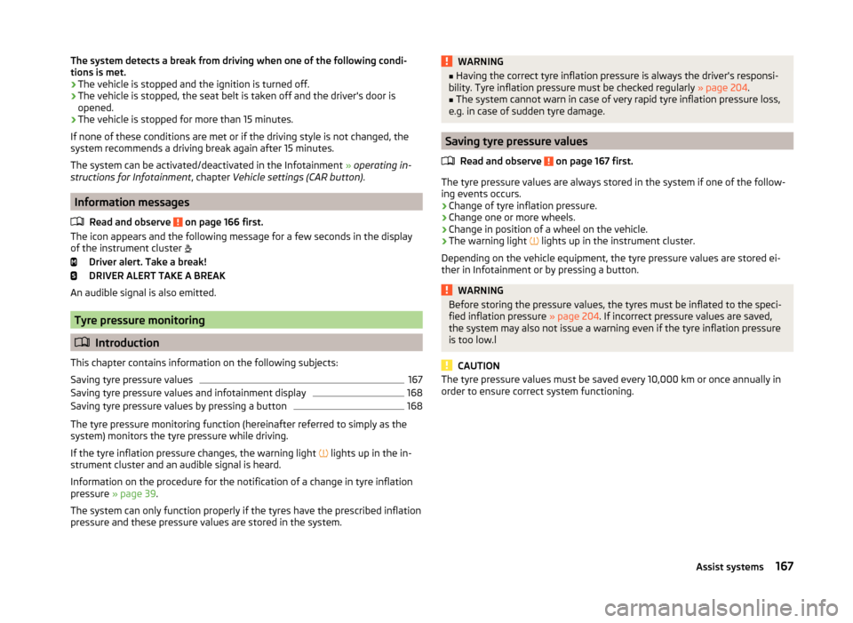
The icon appears and the following message for a few seconds in the display
of the instrument cluster
Driver alert. Take a break!
DRIVER ALERT TAKE A BREAK
An audible signal is also emitted.
Tyre pressure monitoring
Introduction
This chapter contains information on the following subjects:
Saving tyre pressure values
167
Saving tyre pressure values and infotainment display
168
Saving tyre pressure values by pressing a button
168
The tyre pressure monitoring function (hereinafter referred to simply as the
system) monitors the tyre pressure while driving.
If the tyre inflation pressure changes, the warning light lights up in the in-
strument cluster and an audible signal is heard.
Information on the procedure for the notification of a change in tyre inflation
pressure » page 39 .
The system can only function properly if the tyres have the prescribed inflation
pressure and these pressure values are stored in the system.
WARNING■ Having the correct tyre inflation pressure is always the driver's responsi-
bility. Tyre inflation pressure must be checked regularly » page 204.■
The system cannot warn in case of very rapid tyre inflation pressure loss,
e.g. in case of sudden tyre damage.
Saving tyre pressure values
Read and observe
on page 167 first.
The tyre pressure values are always stored in the system if one of the follow-ing events occurs.
› Change of tyre inflation pressure.
› Change one or more wheels.
› Change in position of a wheel on the vehicle.
› The warning light
lights up in the instrument cluster.
Depending on the vehicle equipment, the tyre pressure values are stored ei-
ther in Infotainment or by pressing a button.
WARNINGBefore storing the pressure values, the tyres must be inflated to the speci-
fied inflation pressure » page 204. If incorrect pressure values are saved,
the system may also not issue a warning even if the tyre inflation pressure
is too low.l
CAUTION
The tyre pressure values must be saved every 10,000 km or once annually in
order to ensure correct system functioning.167Assist systems
Page 171 of 280
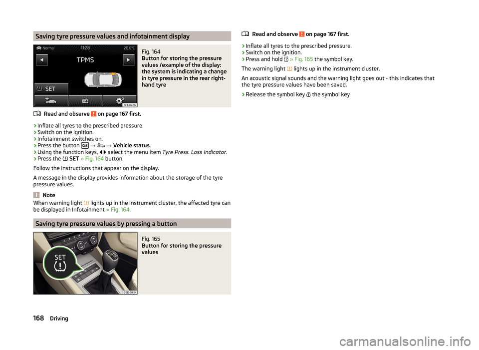
Saving tyre pressure values and infotainment displayFig. 164
Button for storing the pressure
values /example of the display:
the system is indicating a change
in tyre pressure in the rear right-
hand tyre
Read and observe on page 167 first.
›
Inflate all tyres to the prescribed pressure.
›
Switch on the ignition.
›
Infotainment switches on.
›
Press the button
→
→ Vehicle status .
›
Using the function keys,
select the menu item
Tyre Press. Loss Indicator .
›
Press the
SET » Fig. 164 button.
Follow the instructions that appear on the display.
A message in the display provides information about the storage of the tyre
pressure values.
Note
When warning light lights up in the instrument cluster, the affected tyre can
be displayed in Infotainment » Fig. 164.
Saving tyre pressure values by pressing a button
Fig. 165
Button for storing the pressure
values
Read and observe on page 167 first.›
Inflate all tyres to the prescribed pressure.
›
Switch on the ignition.
›
Press and hold
» Fig. 165 the symbol key.
The warning light
lights up in the instrument cluster.
An acoustic signal sounds and the warning light goes out - this indicates that the tyre pressure values have been saved.
›
Release the symbol key
the symbol key
168Driving
Page 178 of 280
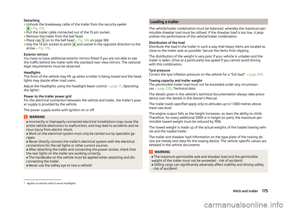
Detaching›Unhook the breakaway cable of the trailer from the security eyeletB
» Fig. 178.
›
Pull the trailer cable connected out of the 13-pin socket.
›
Remove the trailer from the ball head.
›
Place cap
5
on to the ball head » Fig. 166 on page 169 .
›
Grip the 13-pin socket at point
A
and swivel in the opposite direction to the
arrow » Fig. 178 .
Exterior mirrors
You have to have additional exterior mirrors fitted if you are not able to see
the traffic behind the trailer with the standard rear-view mirrors. The national
legal requirements must be observed.
Headlights
The front of the vehicle may lift up when a trailer is being towed and the head-
lights may dazzle other road users.
Adjust the headlights using the headlight beam control » page 71, Operating
the lights 1)
.
Power to the trailer power grid
For the electrical connection between the vehicle and trailer, the trailer's pow-
er supply is provided by the vehicle.
The power supply works with ignition on or off.
WARNING■ Incorrectly or improperly connected electrical installations may cause the
entire vehicle electronics to malfunction, and may lead to accidents and se-
rious injury from electric shock.■
Work on the electrical system must only be carried out by specialist ga-
rages.
■
Never directly connect the trailer's electrical system with the electrical
connections for the tail lights or other current sources.
■
After attaching the trailer and connecting the power socket, check that
the rear lights on the trailer are working correctly.
■
The handbrake on the vehicle must be applied when attaching and dis-
connecting the trailer.
■
Never use the safety eye to tow a vehicle!
Loading a trailer
The vehicle/trailer combination must be balanced. whereby the maximum per-
missible drawbar load must be utilised. If the drawbar load is too low, it jeop-
ardises the performance of the vehicle/trailer combination.
Distribution of the load
Distribute the load in the trailer in such a way that heavy items are located as
close to the trailer axle as possible. Secure the items from slipping.
The distribution of the weight is very poor if your vehicle is unladen and the
trailer is laden. Drive at a particularly low speed if you cannot avoid driving
with this combination.
Tyre pressure
Correct the tyre inflation pressure on the vehicle for a “full load” » page 204.
Towing capacity and trailer weight
The permissible trailer load must not be exceeded under any circumstan-
ces » page 238 , Technical data .
The details given in the vehicle's technical documentation always take prece-
dence over the details in the Owner's Manual.
The trailer loads specified apply only to altitudes up to 1 000 metres above
mean sea level.
The engine output falls as the height increases, as does the ability to climb.
Therefore, for every additional 1000 m in height (or part), the maximum per-
missible towed weight must be reduced by 10%.
The towed weight is made up of the actual weights of the loaded towing vehi-
cle and the loaded trailer.
The trailer and drawbar load information on the type plate of the towing de-
vice are merely test data for the towing device. The vehicle-specific values are
detailed in the vehicle documents.WARNING■ The maximum permissible axle and drawbar load and the permissible
weight of the trailer must not be exceeded - risk of accident!■
Sliding cargo can significantly adversely affect stability and driving safety
- risk of accident!
1)
Applies to vehicles with bi-xenon headlights.
175Hitch and trailer
Page 179 of 280
Trailer operation
Driving speed
For safety reasons, do not drive faster than 80 km/h when hitching a trailer.
Immediately reduce your speed as soon as even the slightest swaying of the
trailer is detected. Never attempt to stop the trailer from “swaying” by acceler-
ating.
Brakes
Apply the brakes in good time! If the trailer is fitted with a trailer brake, apply
the brakes gently at first, then brake firmly. This will avoid brake jolts resulting
from the trailer wheels locking.
On downhill sections shift down a gear in good time to also use the engine as
a brake.
Engine overheating
If the needle for the coolant temperature gauge moves into the right-hand
area or the red area of the scale, the speed must be reduced immediately.
Stop and switch off the engine if the warning symbol in the instrument clus-
ter » page 41 lights up.
The following information must be observed » page 41,
Coolant
.
The coolant temperature can be reduced by switching on the heating.WARNING■ Always drive particularly carefully with the trailer.■Adapt your speed to the conditions of the road surface and to the traffic
situation.
CAUTION
If you tow a trailer frequently, you should also have your vehicle inspected be-
tween service intervals.
Anti-theft alarm system
If the vehicle is locked, the alarm is activated when the electrical connection to
the trailer is interrupted.
Always switch off the anti-theft alarm system before a trailer is coupled or un-
coupled » page 59 .
Conditions for including a trailer in the anti-theft alarm system.
The vehicle is factory-fitted with an anti-theft alarm system and a towing
device.
The trailer is electrically connected to the towing vehicle by means of the
trailer socket.
The electrical system of the vehicle and trailer is functional.
the vehicle is locked with the vehicle key and the anti-theft alarm system
is activated.
CAUTION
For technical reasons, trailers with rear LED lights cannot be connected to the
anti-theft alarm system.176Driving
Page 187 of 280
■Do not remove snow or ice from glass parts using warm or hot water – risk of
cracks forming in the glass.■
Make sure that when removing snow and ice from the windows, the labels
attached to the vehicle by the factory are not damaged.
CAUTION
Information for cleaning windows■Do not clean the inside of the windows with sharp-edged objects or corro-
sive and acidic cleaning agents – there is a risk of damaging the heating ele-
ments or window aerial.■
When drying the windows after washing the vehicle, do not use window
leathers that have been used to polish the bodywork. Residues of preserva-
tives in the window leather can dirty the window and reduce visibility.
Headlight glasses
Read and observe
and on page 182 first.
Clean plastic front headlight lenses using clean, warm water and soap.
CAUTION
■The headlights are never to be wiped dry - there is a risk of damaging the
protective lacquer and the headlight glass subsequently developing cracks.■
Do not use sharp objects to clean the glasses - there is a risk of damaging
the protective lacquer and the headlight glasses subsequently developing
cracks.
■
Do not use any aggressive cleaning or chemical solvent products to clean the
headlights – risk of damaging the headlight lenses.
Camera lens
Read and observe
and on page 182 first.
Moisten the lens of the rear view camera first with clean water and then dry
with a dry cloth.
Remove the snow from the lens with a brush and the ice from the lens with
de-icing agents specifically developed for these purposes.
CAUTION■ Remove snow or ice on the lens with warm or hot water - there is a risk of
damaging the lens.■
Never use cleaners containing abrasive effect to clean the lens.
■
Never use pressurized water or steam jet to clean the lens.
Door closing cylinder
Read and observe
and on page 182 first.
Specific products must be used for de-icing door lock cylinders.
CAUTION
Make sure that as little water as possible gets into the locking cylinder when
washing the vehicle - there is a risk of freezing the lock cylinder!
Cavity protection
Read and observe
and on page 182 first.
All the cavities of your vehicle which are at risk from corrosion are protected
for life by a layer of protective wax applied in the factory.
Wax protection does not require to be inspected or re-treated.
If any small amount of wax flow out of the cavities at high temperatures, these
must be removed with a plastic scraper and the stains cleaned using a petrole-
um cleaner.
WARNINGSafety regulations should be observed when using petroleum cleaner to re-
move wax – risk of fire!
Jack
Read and observe
and on page 182 first.
The jack is maintenance-free.
If necessary, the moving parts of the jack should be lubricated with a suitable
lubricant.
184General Maintenance
Page 198 of 280
NoteThe location of the inspection points in the engine compartment of petrol and
diesel engines is practically identical.
Radiator fan
Read and observe
and on page 193 first.
The radiator fan is powered by an electric motor. Operation is controlled ac-
cording to the temperature of the coolant.
WARNINGAfter switching off the ignition, the fan can intermittently continue to oper-
ate for approx. 10 minutes.
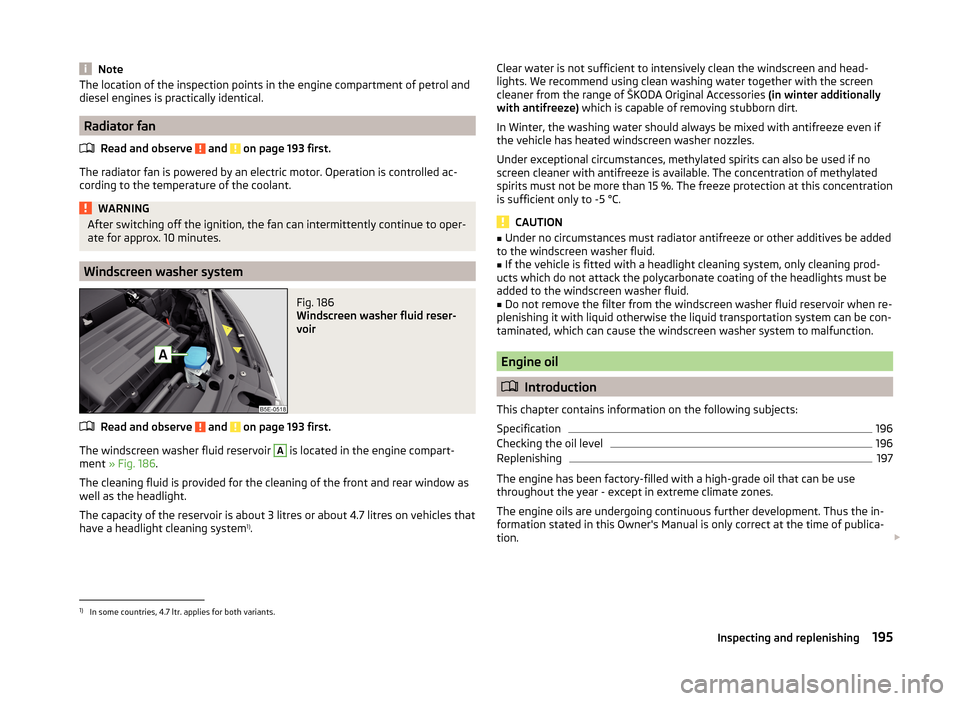
Windscreen washer system
Fig. 186
Windscreen washer fluid reser-
voir
Read and observe and on page 193 first.
The windscreen washer fluid reservoir
A
is located in the engine compart-
ment » Fig. 186 .
The cleaning fluid is provided for the cleaning of the front and rear window as
well as the headlight.
The capacity of the reservoir is about 3 litres or about 4.7 litres on vehicles that
have a headlight cleaning system 1)
.
Clear water is not sufficient to intensively clean the windscreen and head-
lights. We recommend using clean washing water together with the screen
cleaner from the range of ŠKODA Original Accessories (in winter additionally
with antifreeze) which is capable of removing stubborn dirt.
In Winter, the washing water should always be mixed with antifreeze even if
the vehicle has heated windscreen washer nozzles.
Under exceptional circumstances, methylated spirits can also be used if no
screen cleaner with antifreeze is available. The concentration of methylated
spirits must not be more than 15 %. The freeze protection at this concentration
is sufficient only to -5 °C.
CAUTION
■ Under no circumstances must radiator antifreeze or other additives be added
to the windscreen washer fluid.■
If the vehicle is fitted with a headlight cleaning system, only cleaning prod-
ucts which do not attack the polycarbonate coating of the headlights must be
added to the windscreen washer fluid.
■
Do not remove the filter from the windscreen washer fluid reservoir when re-
plenishing it with liquid otherwise the liquid transportation system can be con-
taminated, which can cause the windscreen washer system to malfunction.
Engine oil
Introduction
This chapter contains information on the following subjects:
Specification
196
Checking the oil level
196
Replenishing
197
The engine has been factory-filled with a high-grade oil that can be use
throughout the year - except in extreme climate zones.
The engine oils are undergoing continuous further development. Thus the in- formation stated in this Owner's Manual is only correct at the time of publica-
tion.
1)
In some countries, 4.7 ltr. applies for both variants.
195Inspecting and replenishing
Page 201 of 280
WARNING (Continued)■If coolant is swallowed, consult a doctor immediately.■Never spill operating fluids over the hot engine - risk of fire.
CAUTION
■If for some reason it is not possible to top up the coolant under the current
circumstances, do not continue driving! Switch off the engine and seek as-
sistance from a specialist garage.■
If the expansion tank is empty, do not top up with coolant. The system could
aerate - risk of engine damage,
do not continue driving! Switch off the en-
gine and seek assistance from a specialist garage.
■
The amount of coolant additive in the coolant must never be allowed to be
less than 40 %.
■
Over 60 % of coolant additive in the coolant reduces the antifreeze protec-
tion and coolant effectiveness.
■
A coolant additive that does not comply with the correct specification can
significantly reduce the corrosion protection of the cooling system.
■
Any faults resulting from corrosion may cause a loss of coolant and can con-
sequently result in major engine damage!
■
Do not fill the coolant above the mark
A
» Fig. 188 on page 198 .
■
If an error occurs, leading to the engine overheating, the help of a professio-
nal garage is to be sought - there is a risk of serious engine damage occurring.
■
Additional headlights and other attached components in front of the air inlet
impair the cooling efficiency of the coolant.
■
Never cover the radiator - there is a risk of the engine overheating.
Note
On vehicles that are fitted with an auxiliary heater (auxiliary heating and venti-
lation), the coolant capacity is approx. 1 l larger.
Checking the coolant level
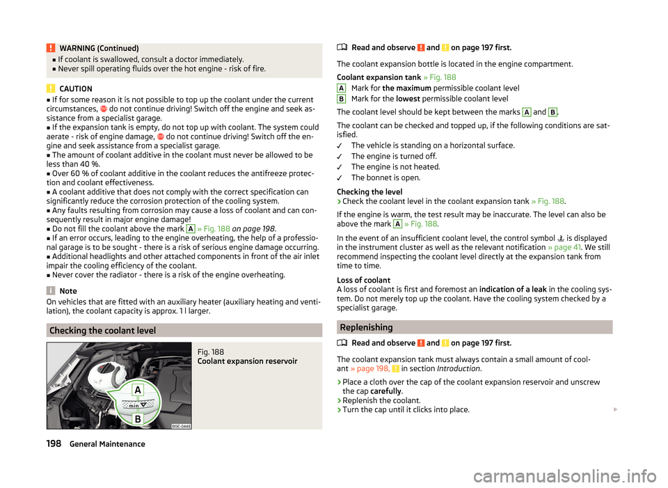
Fig. 188
Coolant expansion reservoir
Read and observe and on page 197 first.
The coolant expansion bottle is located in the engine compartment.
Coolant expansion tank » Fig. 188
Mark for the maximum permissible coolant level
Mark for the lowest permissible coolant level
The coolant level should be kept between the marks
A
and
B
.
The coolant can be checked and topped up, if the following conditions are sat-
isfied.
The vehicle is standing on a horizontal surface.
The engine is turned off.
The engine is not heated.
The bonnet is open.
Checking the level
›
Check the coolant level in the coolant expansion tank » Fig. 188.
If the engine is warm, the test result may be inaccurate. The level can also be
above the mark
A
» Fig. 188 .
In the event of an insufficient coolant level, the control symbol is displayed
in the instrument cluster as well as the relevant notification » page 41. We still
recommend inspecting the coolant level directly at the expansion tank from
time to time.
Loss of coolant
A loss of coolant is first and foremost an indication of a leak in the cooling sys-
tem. Do not merely top up the coolant. Have the cooling system checked by a
specialist garage.
Replenishing
Read and observe
and on page 197 first.
The coolant expansion tank must always contain a small amount of cool-
ant » page 198, in section Introduction .
›
Place a cloth over the cap of the coolant expansion reservoir and unscrew
the cap carefully .
›
Replenish the coolant.
›
Turn the cap until it clicks into place.
AB198General Maintenance
Page 225 of 280
Vehicles with manual transmission may be towed in with a tow bar or a tow
rope or with the front or rear wheels raised.
Vehicles with automatic transmission may be towed in with a tow bar or a tow
rope or with the front wheels raised. If the vehicle is raised at rear, the auto-
matic gearbox is damaged!
Driver of the tow vehicle›
Engage the clutch gently when starting off or depress the accelerator partic-
ularly gently if the vehicle is fitted with an automatic gearbox.
›
Only then approach correctly when the rope is taut.
The maximum towing speed is 50 km/h.
Driver of the towed vehicle
›
Switch on the ignition so that the steering wheel is not locked and so that
the turn signal lights, windscreen wipers and windscreen washer system can
be used.
›
Take the vehicle out of gear or move the selector lever into position N if the
vehicle is fitted with an automatic gearbox.
Please note that the brake servo unit and power steering only operate if the
engine is running. If the engine is not running, significantly more physical force
is required to depress the brake pedal and steer the vehicle.
If using a tow rope, ensure that it is always kept taught.
Both drivers should be familiar with the problems which might possibly occur while a vehicle is being towed. Unskilled drivers should not attempt to tow in
another vehicle or to be towed in.
The vehicle must be transported on a special breakdown vehicle or trailer if it
is not possible to tow in the vehicle in the way described or if the towing dis-
tance is greater than 50 km.
WARNING■ When towing, respect the national legal provisions, especially those
which relate to the identification of the towing vehicle and the vehicle be-
ing towed.■
When towing, exercise increased caution.
■
Spiral tow ropes must not be used for towing » Fig. 207-
, the towing
eye may unscrew out of the vehicle - risk of accident.
■
The tow rope should not be twisted - risk of accident.
CAUTION■ Do not tow start the engine – there is a risk of damaging the engine and the
catalytic converter. The battery from another vehicle can be used as a jump-
start aid » page 220 , Jump-starting .■
If the gearbox no longer contains any oil, your vehicle must only be towed
with the front axle raised clear of the ground or on a breakdown vehicle or
trailer.
■
To protect both vehicles when tow-starting or towing, the tow rope should
be elastic. Thus one should only use plastic fibre rope or a rope made out of a
similarly elastic material.
■
There is always a risk of excessive stresses and damage resulting at the
points to which you attach the tow rope or tow bar when you attempt to tow a
vehicle which is not standing on a paved road.
■
Attach the tow rope or the tow bar to the towing eyes » page 222
or » page 223 to the detachable ball head of the towing equip-
ment » page 169 .
Note
We recommend using a tow rope from ŠKODA Original Accessories available
from a ŠKODA Partner.
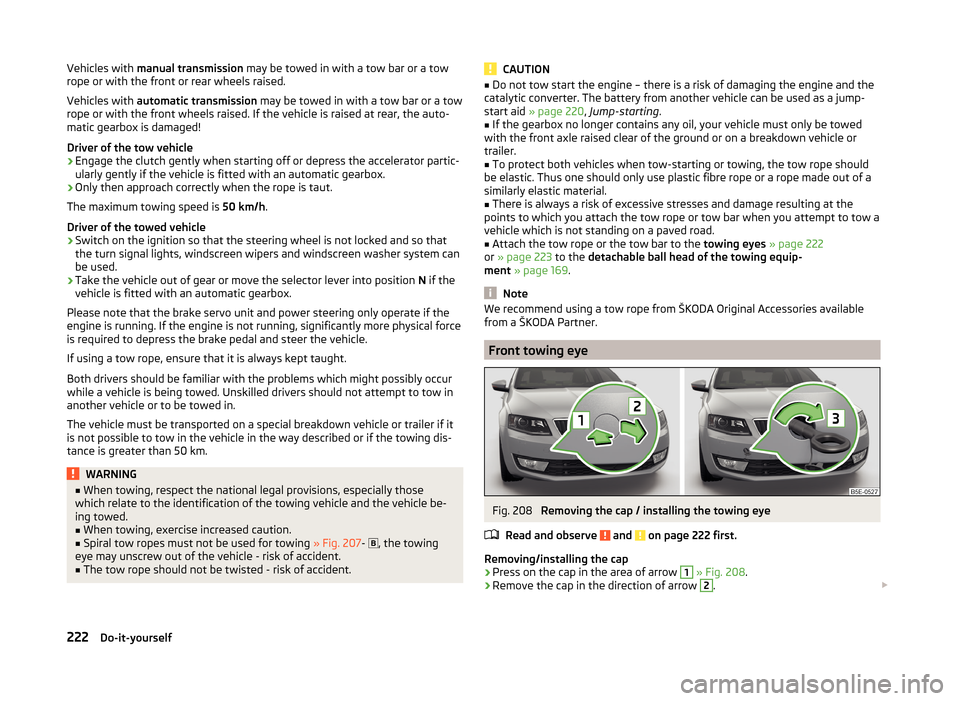
Front towing eye
Fig. 208
Removing the cap / installing the towing eye
Read and observe
and on page 222 first.
Removing/installing the cap
›
Press on the cap in the area of arrow
1
» Fig. 208 .
›
Remove the cap in the direction of arrow
2
.
222Do-it-yourself
Page 233 of 280
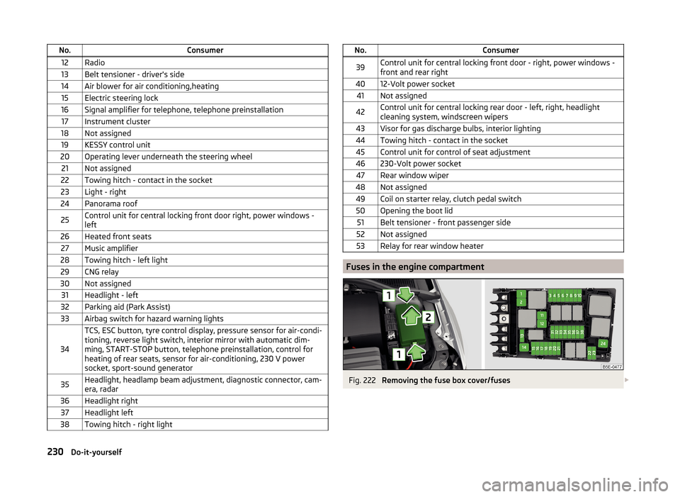
No.Consumer12Radio13Belt tensioner - driver's side14Air blower for air conditioning,heating15Electric steering lock16Signal amplifier for telephone, telephone preinstallation17Instrument cluster18Not assigned19KESSY control unit20Operating lever underneath the steering wheel21Not assigned22Towing hitch - contact in the socket23Light - right24Panorama roof25Control unit for central locking front door right, power windows -
left26Heated front seats27Music amplifier28Towing hitch - left light29CNG relay30Not assigned31Headlight - left32Parking aid (Park Assist)33Airbag switch for hazard warning lights
34
TCS, ESC button, tyre control display, pressure sensor for air-condi-
tioning, reverse light switch, interior mirror with automatic dim-
ming, START-STOP button, telephone preinstallation, control for
heating of rear seats, sensor for air-conditioning, 230 V power
socket, sport-sound generator35Headlight, headlamp beam adjustment, diagnostic connector, cam-
era, radar36Headlight right37Headlight left38Towing hitch - right lightNo.Consumer39Control unit for central locking front door - right, power windows -
front and rear right4012-Volt power socket41Not assigned42Control unit for central locking rear door - left, right, headlight
cleaning system, windscreen wipers43Visor for gas discharge bulbs, interior lighting44Towing hitch - contact in the socket45Control unit for control of seat adjustment46230-Volt power socket47Rear window wiper48Not assigned49Coil on starter relay, clutch pedal switch50Opening the boot lid51Belt tensioner - front passenger side52Not assigned53Relay for rear window heater
Fuses in the engine compartment
Fig. 222
Removing the fuse box cover/fuses
230Do-it-yourself