warning light SKODA OCTAVIA 2016 3.G / (5E) Workshop Manual
[x] Cancel search | Manufacturer: SKODA, Model Year: 2016, Model line: OCTAVIA, Model: SKODA OCTAVIA 2016 3.G / (5E)Pages: 324, PDF Size: 48.85 MB
Page 111 of 324
WARNING■The auxiliary heating must never be operated in closed rooms (e.g. garag-
es) – risk of poisoning!■
The auxiliary heating must not be allowed to run during refuelling – risk
of fire.
■
The exhaust pipe of the auxiliary heating is located on the underside of
the vehicle. If you want to use the auxiliary heating, do not park the vehicle
in places where the exhaust fumes can come into contact with flammable
materials such as dry grass, undergrowth, leaves, spilled fuel etc. - There is
a risk of fire.
CAUTION
The air inlet in front of the windscreen must be free (e.g. of ice, snow or
leaves) to ensure that the auxiliary heating operates properly.
Note
■ The auxiliary heating only switches the blower on, if it has achieved a coolant
temperature of approx. 50 °C.■
In the engine compartment, water vapour may form during the operation of
the heater.
Switch on / off
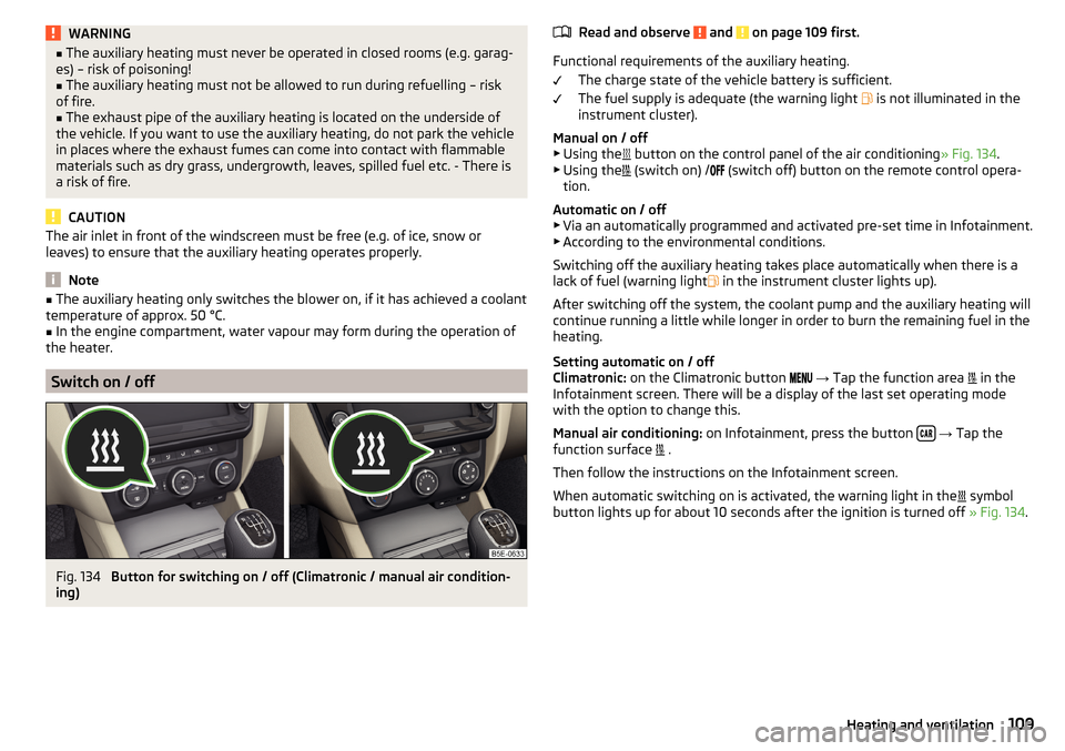
Fig. 134
Button for switching on / off (Climatronic / manual air condition-
ing)
Read and observe and on page 109 first.
Functional requirements of the auxiliary heating.
The charge state of the vehicle battery is sufficient.
The fuel supply is adequate (the warning light
is not illuminated in the
instrument cluster).
Manual on / off ▶ Using the
button on the control panel of the air conditioning » Fig. 134.
▶ Using the
(switch on) /
(switch off) button on the remote control opera-
tion.
Automatic on / off ▶ Via an automatically programmed and activated pre-set time in Infotainment.
▶ According to the environmental conditions.
Switching off the auxiliary heating takes place automatically when there is a
lack of fuel (warning light in the instrument cluster lights up).
After switching off the system, the coolant pump and the auxiliary heating will
continue running a little while longer in order to burn the remaining fuel in the
heating.
Setting automatic on / off
Climatronic: on the Climatronic button
→ Tap the function area
in the
Infotainment screen. There will be a display of the last set operating mode
with the option to change this.
Manual air conditioning: on Infotainment, press the button
→ Tap the
function surface .
Then follow the instructions on the Infotainment screen.
When automatic switching on is activated, the warning light in the symbol
button lights up for about 10 seconds after the ignition is turned off » Fig. 134.
109Heating and ventilation
Page 112 of 324
Operation in InfotainmentFig. 135
Aux. heating: Main menu/set preset time
Read and observe
and on page 109 first.
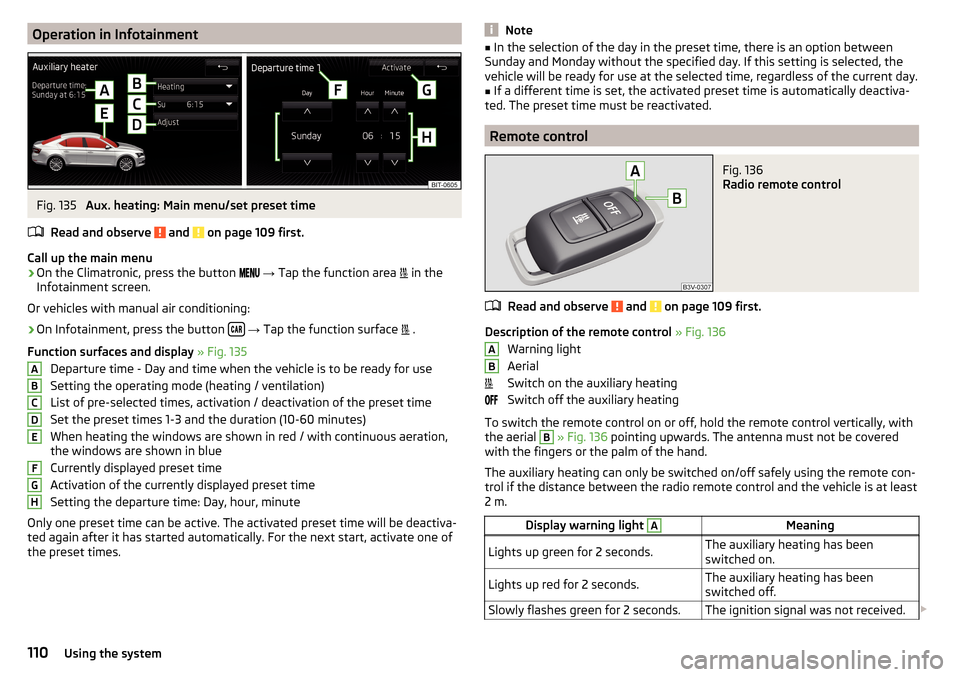
Call up the main menu
›
On the Climatronic, press the button
→ Tap the function area
in the
Infotainment screen.
Or vehicles with manual air conditioning:
›
On Infotainment, press the button
→ Tap the function surface
.
Function surfaces and display » Fig. 135
Departure time - Day and time when the vehicle is to be ready for use
Setting the operating mode (heating / ventilation)
List of pre-selected times, activation / deactivation of the preset time Set the preset times 1-3 and the duration (10-60 minutes)
When heating the windows are shown in red / with continuous aeration,
the windows are shown in blue
Currently displayed preset time
Activation of the currently displayed preset time
Setting the departure time: Day, hour, minute
Only one preset time can be active. The activated preset time will be deactiva-
ted again after it has started automatically. For the next start, activate one of
the preset times.
ABCDEFGHNote■ In the selection of the day in the preset time, there is an option between
Sunday and Monday without the specified day. If this setting is selected, the
vehicle will be ready for use at the selected time, regardless of the current day.■
If a different time is set, the activated preset time is automatically deactiva-
ted. The preset time must be reactivated.
Remote control
Fig. 136
Radio remote control
Read and observe and on page 109 first.
Description of the remote control » Fig. 136
Warning light
Aerial
Switch on the auxiliary heating
Switch off the auxiliary heating
To switch the remote control on or off, hold the remote control vertically, with the aerial
B
» Fig. 136 pointing upwards. The antenna must not be covered
with the fingers or the palm of the hand.
The auxiliary heating can only be switched on/off safely using the remote con-
trol if the distance between the radio remote control and the vehicle is at least
2 m.
Display warning light AMeaningLights up green for 2 seconds.The auxiliary heating has been
switched on.Lights up red for 2 seconds.The auxiliary heating has been
switched off.Slowly flashes green for 2 seconds.The ignition signal was not received. AB110Using the system
Page 113 of 324

Display warning light AMeaning
Quickly flashes green for 2 seconds.
The auxiliary heating is blocked, e.g.
because the tank is nearly empty or
there is a fault in the auxiliary heat-
ing.Flashes red for 2 seconds.The switch off signal was not re-
ceived.Lights up orange for 2 seconds, then
green or red.The battery is weak, however the
switching on or off signal was re-
ceived.Lights up orange for 2 seconds, then
flashes green or red.The battery is weak, however the
switching on or off signal was not re-
ceived.Flashes orange for 5 seconds.The battery is discharged, however
the switching on or off signal was not
received.
Replace the battery » page 275.
CAUTION
■
The remote control must be protected against moisture, severe shocks and
direct sunlight - Otherwise, there is a risk of damage to the remote control.■
The range of the remote control with a charged battery is a few hundred me-
tres (depending on obstructions between the remote control and the vehicle,
weather conditions, the battery condition etc.).
111Heating and ventilation
Page 190 of 324
Driving
Starting-off and Driving
Starting and stopping the engine
Introduction
This chapter contains information on the following subjects:
Electronic immobiliser and steering lock
188
Switch on/off ignition
189
Starting / stopping the engine
189
Problems with the engine start - vehicles with starter button
190
Depending on equipment fitted, it is possible to switch the ignition on/off and
start/stop the engine with the key in the ignition or using the starter button .
WARNING■
Never switch off the engine before the vehicle is stationary – risk of acci-
dent!■
While driving with the engine stopped the ignition must always be
switched on. Otherwise, the steering may lock - danger of an accident!
■
Do not withdraw the ignition key from the ignition lock until the vehicle
has come to a stop » page 193, Parking . Otherwise, the steering may lock -
danger of an accident!
■
Never leave the vehicle unattended with the engine running - there is a
risk of theft etc!
■
Never (e.g. in garages) run the engine in a closed place - there is a risk of
poisoning and death!
CAUTION
■ Only start the engine when the engine and the vehicle are stationary - there
is a risk of starter and engine damage!■
Do not push-start the engine – There is a risk of damaging the engine and
the catalytic converter! The battery from another vehicle can be used as a
jump-start aid.
■
On vehicles with the starter button, pay attention to where the key is loca-
ted. The system can recognize the valid key, even if it has been accidentally
left on the vehicle roof - there is danger of loss or damage to the key!
NoteDo not warm up the engine while the vehicle is stationary. If possible, start
your journey as soon as the engine has started. Through this, the engine rea-
ches its operating temperature faster.
Electronic immobiliser and steering lock
Read and observe
and on page 188 first.
The electronic immobiliser (hereinafter referred to as immobiliser) makes the
theft or unauthorised use of your vehicle more difficult.
Immobiliser
The immobiliser allows the engine to start provided an original vehicle key only
is used.
Malfunction of the immobiliser
If a component in the immobiliser key fails, it is not possible to start the en-
gine. A corresponding message appears in the display of the instrument clus-
ter to explain the immobiliser is active.
To start, use the other vehicle key or seek help from a specialist garage.
Steering lock - locking
›
On vehicles with ignition lock, remove the key and turn the steering wheel
until the steering lock engages.
›
On vehicles with a starter button, switch off the ignition and open the driv-
er's door. If the driver's door is opened and the ignition is switched off after-
wards, the steering is only locked automatically after the vehicle has been
locked.
Steering lock - unlock
›
On vehicles with ignition lock, insert the key into the ignition and turn on the
ignition. If this is not possible, then move the steering wheel slightly back
and forth, as a result of which the steering lock should unlock.
›
On vehicles with starter button, get into the vehicle and close the driver's
door. Under certain circumstances, the steering lock can be unlocked only
when the ignition is switched on or the engine is started.
WARNINGNever let the vehicle roll with locked steering lock - there is a risk of acci-
dent!188Driving
Page 191 of 324
Switch on/off ignitionFig. 229
Positions of the vehicle key in the ignition lock / starter button
Read and observe
and on page 188 first.
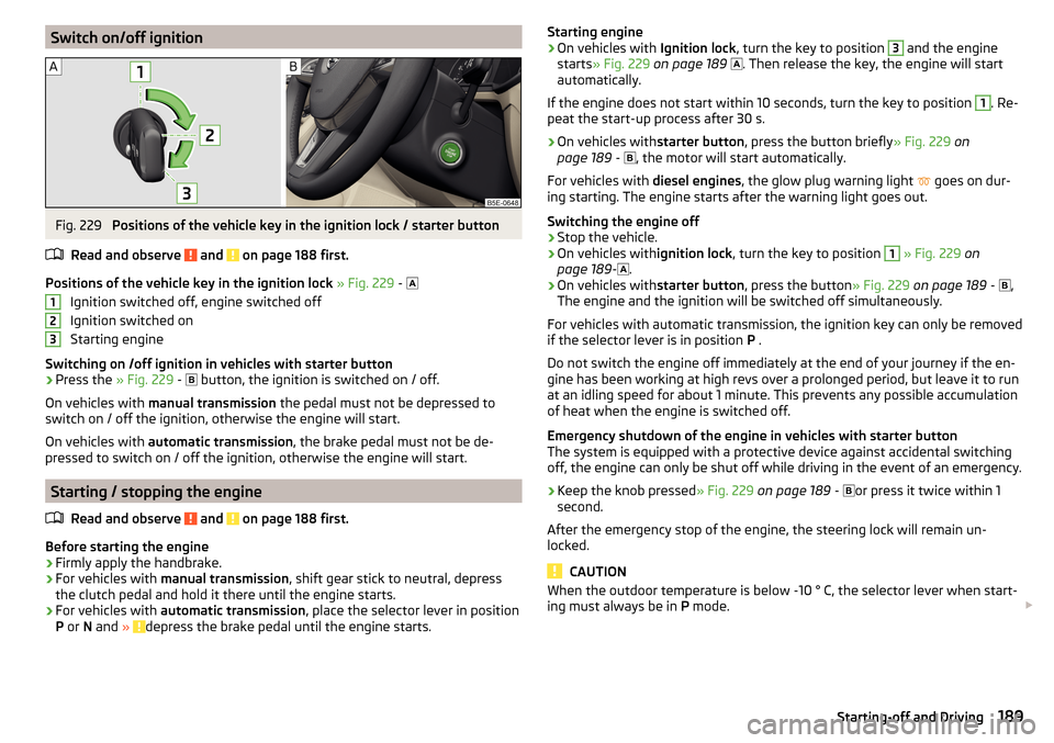
Positions of the vehicle key in the ignition lock » Fig. 229 -
Ignition switched off, engine switched off
Ignition switched on
Starting engine
Switching on /off ignition in vehicles with starter button
›
Press the » Fig. 229 -
button, the ignition is switched on / off.
On vehicles with manual transmission the pedal must not be depressed to
switch on / off the ignition, otherwise the engine will start.
On vehicles with automatic transmission , the brake pedal must not be de-
pressed to switch on / off the ignition, otherwise the engine will start.
Starting / stopping the engine
Read and observe
and on page 188 first.
Before starting the engine
›
Firmly apply the handbrake.
›
For vehicles with manual transmission , shift gear stick to neutral, depress
the clutch pedal and hold it there until the engine starts.
›
For vehicles with automatic transmission , place the selector lever in position
P or N and » depress the brake pedal until the engine starts.
123Starting engine›On vehicles with Ignition lock, turn the key to position 3 and the engine
starts » Fig. 229 on page 189
. Then release the key, the engine will start
automatically.
If the engine does not start within 10 seconds, turn the key to position 1
. Re-
peat the start-up process after 30 s.
›
On vehicles with starter button, press the button briefly » Fig. 229 on
page 189 -
, the motor will start automatically.
For vehicles with diesel engines, the glow plug warning light
goes on dur-
ing starting. The engine starts after the warning light goes out.
Switching the engine off
›
Stop the vehicle.
›
On vehicles with ignition lock, turn the key to position
1
» Fig. 229 on
page 189 -
.
›
On vehicles with
starter button, press the button » Fig. 229 on page 189 -
,
The engine and the ignition will be switched off simultaneously.
For vehicles with automatic transmission, the ignition key can only be removed
if the selector lever is in position P .
Do not switch the engine off immediately at the end of your journey if the en-
gine has been working at high revs over a prolonged period, but leave it to run
at an idling speed for about 1 minute. This prevents any possible accumulation
of heat when the engine is switched off.
Emergency shutdown of the engine in vehicles with starter button
The system is equipped with a protective device against accidental switching
off, the engine can only be shut off while driving in the event of an emergency.
›
Keep the knob pressed » Fig. 229 on page 189 -
or press it twice within 1
second.
After the emergency stop of the engine, the steering lock will remain un-
locked.
CAUTION
When the outdoor temperature is below -10 ° C, the selector lever when start-
ing must always be in P mode. 189Starting-off and Driving
Page 194 of 324
Before negotiating a long or steep gradient , reduce speed and shift down a
gear. As a result, the braking effect of the engine will be used, reducing the
load on the brakes. If, nevertheless, there is a need for additional braking, it
should be carried out at intervals.
Emergency braking warning - If it is necessary to brake hard, the system may
cause the brake lights to automatically flash, to alert the traffic behind.
New brake pads must first be““run in”” because these do not initially have the
best possible braking effect. Drive especially carefully for the first 200 km or
so.
If the brake fluid level is too low, it can cause faults in the braking system ;
the warning light will light up in the instrument cluster » page 33
,
Braking
system . If the warning light does not light up, yet the stopping distance is per-
ceived to be longer than before, the driving style should be adapted in view of
the unknown cause of the problem, and braking kept to a minimum - seek the
help of a specialist garage without delay.
The brake booster increases the pressure generated with the brake pedal. The
brake booster only operates when the engine is running.WARNING■ Greater physical effort for braking is required when the engine is switch-
ed off – risk of accident!■
During the braking procedure on a vehicle with manual transmission,
when the vehicle is in gear and at low revs, press the clutch pedal. Other-
wise, the functionality of the brake system may be impaired – risk of acci-
dent!
■
Do not depress the brake pedal, if there is no requirement to slow down.
This causes the brakes to overheat and can also result in a longer braking
distance and excessive wear - There is a risk of an accident!
■
Only brake for the purpose of drying and cleaning the brake discs if the
traffic conditions permit this. Do not place any other road users in jeopardy.
■
Recommendations for new brake pads should be followed.
■
When stopping and parking, the parking brake should always be applied
firmly, otherwise the vehicle could move off - There is a risk of an accident!
■
If a front spoiler, full wheel trim, etc. is mounted retrospectively, it must
be ensured that the air supply to the front wheel brakes is not reduced.
Otherwise, the front brakes could be in danger of overheating – There is a
risk of an accident!
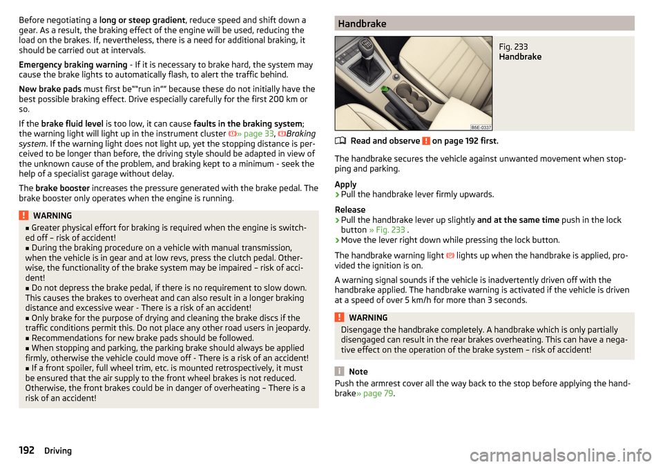
HandbrakeFig. 233
Handbrake
Read and observe on page 192 first.
The handbrake secures the vehicle against unwanted movement when stop- ping and parking.
Apply
›
Pull the handbrake lever firmly upwards.
Release
›
Pull the handbrake lever up slightly and at the same time push in the lock
button » Fig. 233 .
›
Move the lever right down while pressing the lock button.
The handbrake warning light lights up when the handbrake is applied, pro-
vided the ignition is on.
A warning signal sounds if the vehicle is inadvertently driven off with the
handbrake applied. The handbrake warning is activated if the vehicle is driven
at a speed of over 5 km/h for more than 3 seconds.
WARNINGDisengage the handbrake completely. A handbrake which is only partially
disengaged can result in the rear brakes overheating. This can have a nega-
tive effect on the operation of the brake system – risk of accident!
Note
Push the armrest cover all the way back to the stop before applying the hand-
brake » page 79 .192Driving
Page 195 of 324
ParkingRead and observe
on page 192 first.
When stopping and parking, look for a place with a suitable surface » .
Only carry out the activities while parking in the specified order.
›
Bring the vehicle to a stop and depress the brake pedal.
›
Firmly apply the handbrake.
›
On vehicles with automatic transmission place the selector lever in the P po-
sition.
›
Switch off the engine.
›
For vehicles with Manual transmission , select 1st gear or Reverse gear R .
›
Release the brake pedal.
WARNING■
The parts of the exhaust system can become very hot. Therefore, never
stop the vehicle in places where the underside of your vehicle could come
into contact with flammable materials (e.g. dry grass, leaves, spilled fuel or
the like). - Risk of fire and serious injury can occur!■
When leaving the vehicle never leave people unattended in the car who
could, for example, lock the vehicle or release the brake - There is a risk of
an accident and an injury!
Manual shifting of gears and pedals
Introduction
This chapter contains information on the following subjects:
Manual gear changing
193
Pedals
194
CAUTION
When stopping on a slope, never try to hold the vehicle using the clutch and
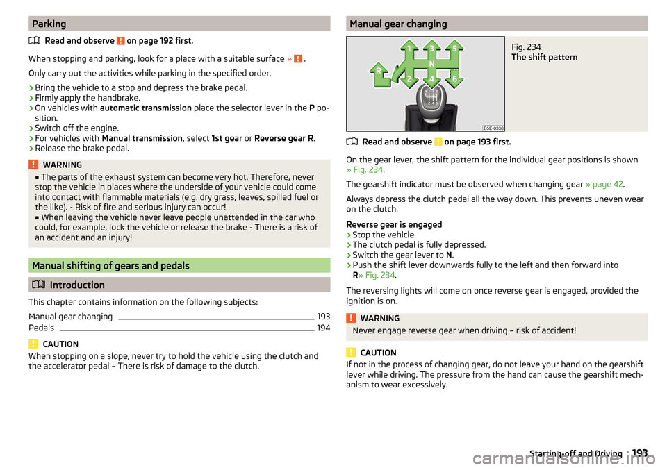
the accelerator pedal – There is risk of damage to the clutch.Manual gear changingFig. 234
The shift pattern
Read and observe on page 193 first.
On the gear lever, the shift pattern for the individual gear positions is shown
» Fig. 234 .
The gearshift indicator must be observed when changing gear » page 42.
Always depress the clutch pedal all the way down. This prevents uneven wear
on the clutch.
Reverse gear is engaged
›
Stop the vehicle.
›
The clutch pedal is fully depressed.
›
Switch the gear lever to N.
›
Push the shift lever downwards fully to the left and then forward into
R » Fig. 234 .
The reversing lights will come on once reverse gear is engaged, provided the
ignition is on.
WARNINGNever engage reverse gear when driving – risk of accident!
CAUTION
If not in the process of changing gear, do not leave your hand on the gearshift
lever while driving. The pressure from the hand can cause the gearshift mech-
anism to wear excessively.193Starting-off and Driving
Page 197 of 324
Forward mode / sport programme - the gear change takes place in the
position S at higher engine speeds than in mode D
(Sprung position) - choice between positions D and S
If the Sport driving mode is selected with the engine running » page 221, Se-
lect the driving mode (Driving Mode Selection) , the transmission is automati-
cally set in the S mode.
E – Economical driving mode
If the driving mode Eco or Individual (engine - Eco) » page 221 is selected and
the selection lever is in the setting D/S, the transmission is automatically set
to mode E. This mode cannot be selected with the selector lever.
The forward mode is switched up or down automatically in mode E at lower en-
gine speeds than in mode D.
Selector lever lock
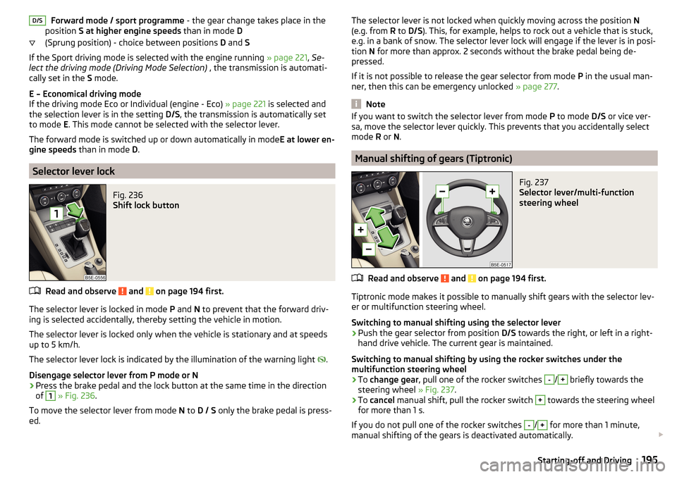
Fig. 236
Shift lock button
Read and observe and on page 194 first.
The selector lever is locked in mode P and N to prevent that the forward driv-
ing is selected accidentally, thereby setting the vehicle in motion.
The selector lever is locked only when the vehicle is stationary and at speeds
up to 5 km/h.
The selector lever lock is indicated by the illumination of the warning light .
Disengage selector lever from P mode or N
›
Press the brake pedal and the lock button at the same time in the direction
of
1
» Fig. 236 .
To move the selector lever from mode N to D / S only the brake pedal is press-
ed.
D/SThe selector lever is not locked when quickly moving across the position N
(e.g. from R to D/S ). This, for example, helps to rock out a vehicle that is stuck,
e.g. in a bank of snow. The selector lever lock will engage if the lever is in posi-
tion N for more than approx. 2 seconds without the brake pedal being de-
pressed.
If it is not possible to release the gear selector from mode P in the usual man-
ner, then this can be emergency unlocked » page 277.
Note
If you want to switch the selector lever from mode P to mode D/S or vice ver-
sa, move the selector lever quickly. This prevents that you accidentally select
mode R or N.
Manual shifting of gears (Tiptronic)
Fig. 237
Selector lever/multi-function
steering wheel
Read and observe and on page 194 first.
Tiptronic mode makes it possible to manually shift gears with the selector lev-
er or multifunction steering wheel.
Switching to manual shifting using the selector lever
›
Push the gear selector from position D/S towards the right, or left in a right-
hand drive vehicle. The current gear is maintained.
Switching to manual shifting by using the rocker switches under the
multifunction steering wheel
›
To change gear , pull one of the rocker switches
-
/
+
briefly towards the
steering wheel » Fig. 237.
›
To cancel manual shift, pull the rocker switch
+
towards the steering wheel
for more than 1 s.
If you do not pull one of the rocker switches
-
/
+
for more than 1 minute,
manual shifting of the gears is deactivated automatically.
195Starting-off and Driving
Page 202 of 324
The sensor is a component of the ACC » page 214 and Front Assist
» page 219 systems.
The sensor function may be impaired in the events of one of the following. ▶ The sensor cover is soiled (e.g. with mud, snow etc.).
▶ The area in front of and around the sensor cover is obscured (e.g. by labels,
auxiliary headlights etc.).
▶ When visibility is poor, (e.g. fog, heavy rain, thick snowfall).
If the sensor is covered or dirty, the corresponding message appears in the in-
strument cluster display for the ACC system » page 218, Malfunctions or Front
Assist system » page 221, Malfunctions .WARNING■
If you suspect that the sensor is damaged, deactivate the ACC system and
Front Assist system » page 216» page 220 . Have the sensor checked by a
specialist garage.■
A collision or damage in the front or lower area of the vehicle could affect
the sensor function - there is risk of accident! Have the sensor checked by
a specialist garage.
■
Do not cover the area in front of and around the sensor cover. This can
lead to impaired function of the sensor - risk of accidents!
CAUTION
Remove the snow with a brush and the ice with a solvent-free de-icer.
Braking and stabilisation systems
Introduction
This chapter contains information on the following subjects:
Stability Control (ESC)
200
ESC Sport
200
Anti-lock braking system (ABS)
201
Engine drag torque control (MSR)
201
Traction control (TCS)
201
Electronic Differential Lock (EDL and XDS)
201
Active steering assist (DSR)
202
Brake Assist (HBA)
202
Hill Start Assist (HHC)
202Multicollision brake (MCB)202Trailer stabilisation system (TSA)202
The brake and stabilization systems are automatically activated each time the
ignition is switched on, unless otherwise indicated.
The error display is in Chapter » page 32, Warning lights .
WARNINGThe general information relating to the use of assistance systems must be
observed » page 199, in section Introduction .
Stability Control (ESC)
Read and observe
on page 200 first.
ESC improves vehicle stability in critical driving situations (e.g. if the vehicle
starts to skid) by the braking the individual wheels to maintain the direction.
If there is a TCS intervention, the indicator light flashes in the instrument
cluster.
ESC Sport
Read and observe
on page 200 first.
ESC Sport allows for a sportier driving style. With ESC Sport activated, no ESC
intervention takes place when the vehicle slightly oversteers and understeers,
and ASR is so limited that the drive wheels can be spun.
Activation
›
Press and hold down the
» Fig. 241 on page 201 button.
›
or: On Infotainment, press the button
→ Press the function area
→
ESC system:
→
ESC Sport
.
With activation the warning light
lights up in the instrument cluster and an
appropriate message is displayed in the instrument cluster.
Deactivation
›
Press the
» Fig. 241 on page 201 button.
›
or: On Infotainment, press the button
→ Press the function area
→
ESC system:
→
Activated
.
With deactivation the warning light extinguishes in the instrument cluster
and an appropriate message is displayed in the instrument cluster.
200Driving
Page 203 of 324
Anti-lock braking system (ABS)Read and observe
on page 200 first.
ABS prevents the wheels locking when braking. Thus helping the driver to
maintain control of the vehicle.
The intervention of the ABS is noticeable from the pulsating movements of
the brake pedal which is accompanied by noises.
When the ABS system is active, do not brake periodically or reduce the pres-
sure on the brake pedal.
Engine drag torque control (MSR)
Read and observe
on page 200 first.
MSR counteracts the tendency of the drive wheels to lock during downshifts
or sudden deceleration (e.g. on icy or an otherwise slippery road surface).
If the drive wheels should lock, then the engine speed is automatically in-
creased. This reduces the braking effect of the engine and the wheels can ro-
tate freely again.
Traction control (TCS)
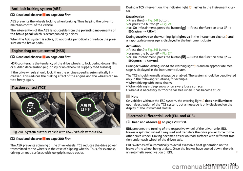
Fig. 241
System button: Vehicle with ESC / vehicle without ESC
Read and observe
on page 200 first.
The ASR prevents spinning of the drive wheels. TCS reduces the drive power transmitted to the wheels in the case of slipping wheels. Thus, for example,
driving on road surfaces with low grip is made easier.
During a TCS intervention, the indicator light flashes in the instrument clus-
ter.
Deactivation›
Press the
» Fig. 241 button.
›
or:press the button
» Fig. 241
›
or: On Infotainment, press the button
→ Press the function area
→
ESC system:
→
ASR off
.
During deactivation the warning light lights up in the instrument cluster
and
an appropriate message is displayed in the instrument cluster.
Activation
›
Press the
» Fig. 241 button.
›
or:press the button
» Fig. 241
›
or: On Infotainment, press the button
→ Press the function area
→
ESC system:
→
Activated
.
During activation extinguished the warning light
is and an appropriate mes-
sage is displayed in the instrument cluster.
The TCS should normally always be enabled. The system should be deactivated
only in the following situations, for example. ▶ When driving with snow chains.
▶ When driving in deep snow or on a very loose surface.
▶ When it is necessary to “rock” a car free when it has become stuck.
Note
On vehicles without the ESC system, the warning light does not illuminate
upon deactivation of the TCS system, but a message is only displayed on the
display of the instrument cluster.
Electronic Differential Lock (EDL and XDS)
Read and observe
on page 200 first.
EDL prevents the turning of the respective wheel of the driven axle. EDL
brakes a spinning wheel if required and transfers the drive power force to the
other drive wheel. Driving becomes easier on road surfaces with different trac-
tion under each wheel of the driven axle.
EDL switches off automatically to avoid excessive heat generation on the
brake of the wheel being braked. Once the brakes have cooled down, there is
an automatic re-activation of EDL.
201Assist systems