trailer SKODA OCTAVIA 2016 3.G / (5E) Owner's Manual
[x] Cancel search | Manufacturer: SKODA, Model Year: 2016, Model line: OCTAVIA, Model: SKODA OCTAVIA 2016 3.G / (5E)Pages: 324, PDF Size: 48.85 MB
Page 5 of 324
Media136Operation136
Audio sources
139
Images
144
Image viewer
144
Video DVD
145
Video player
145
Media Command
147
Operation
147
Telephone
149
Introductory information
149
Pair and connect
152
Use the SIM card in the external module
154
rSAP
155
Telephone functions
157
Text messages (SMS)
161
Hotspot (WLAN) and data connection
163
Hotspot (WLAN)
163
Data connection
164
SmartLink
165
Introductory information
165
Android Auto
166
Apple CarPlay
167
MirrorLink®
167
Navigation
169
Introductory information
169
Search for destination and enter
171
Import my destinations
175
Map
176
Route guidance
179
Route
181Waypoint mode183Traffic reports185
Vehicle systems
187
CAR Vehicle settings
187
Driving
Starting-off and Driving
188
Starting and stopping the engine
188
START-STOPsystem
190
Brakes and Parking
191
Manual shifting of gears and pedals
193
Automatic transmission
194
Running in and economical driving
196
Avoiding damage to your vehicle
198
Assist systems
199
General information
199
Braking and stabilisation systems
200
OFF ROADmode
203
Parking aid (Park Pilot)
204
Reversing camera
207
Park Assist
209
Cruise Control System
212
Adaptive Cruise Control (ACC)
214
Front Assist
219
Select the driving mode (Driving Mode
Selection)
221
Proactive passenger protection (Crew Protect
Assist)
223
Lane Departure Warning (Lane Assist)
224
Traffic sign recognition
226
Fatigue detection
228
Tyre pressure monitoring
229
Towing device and trailer
230
Hitch
230
Using hitch
235General Maintenance
Care and maintenance240
Service work, adjustments and technical
alterations
240
Service intervals
242
Cleaning and care
244
Inspecting and replenishing
248
Fuel
248
Engine compartment
252
Engine oil
255
Coolant
256
Brake fluid
257
Vehicle battery
258
Wheels
260
Wheels and tyres
260
Operating in winter conditions
263
Do-it-yourself
Emergency equipment, and self-help
265
Emergency equipment
265
Changing a wheel
266
Breakdown kit
270
Jump-starting
272
Towing the vehicle
273
Remote - replacing battery
275
Emergency unlocking / locking of doors
276
Replacing windscreen wiper blades
277
Fuses and light bulbs
278
Fuses
278
Bulbs
282
Technical data
Technical data
288
Basic vehicle data
288
Vehicle-specific details per engine type
2963Table of Contents
Page 13 of 324
AbbreviationsAbbreviationDefinitionrpmEngine revolutions per minuteABSAnti-lock brake systemACCAdaptive cruise controlAGAutomatic gearboxAGMVehicle battery typeTCSTraction controlCNGcompressed natural gasCO2Carbon dioxideCOCDeclaration of conformityDPFDiesel particle filterDSGAutomatic double clutch gearboxDSRActive driver-steering recommendationEDLElectronic differential lockECEEconomic Commission for EuropeEPCEPC fault lightESCElectronic Stability ControlRDRim depthEUEuropean UnionG-TECLabelling for natural gas vehiclesHBAHydraulic brake assistHHCUphill start assistKESSYkeyless unlocking, starting and lockingkWKilowatt, measuring unit for outputLEDLighting element typeM1A passenger car constructed primarily for the transport of
peopleMCBMulti-collision brakeMGManual gearboxMPIGasoline engine with a multi-point fuel injectionMSREngine drag torque controlAbbreviationDefinitionN1Panel van intended exclusively or mainly for the transporta-
tion of goodsNmNewton meter, measuring unit for the engine torquePINpersonal identification numberQiStandard for wireless charging by electrical inductionTDI CRDiesel engine with turbo charging and common-rail injection
systemTSATrailer stabilisationTSIPetrol engine with turbo charging and direct injectionVINVehicle identification numberWWatt, unit of powerWi-FiWireless data networkXDSFunctional expansion of the electronic differential lock11Abbreviations
Page 34 of 324
Warning lights
Introduction
This chapter contains information on the following subjects:
Handbrake
33
Braking system
33
Front seat belt warning light
33
Adaptive cruise control (ACC)
33
Power steering / steering lock (KESSY system)
33
Stability control (ESC) / Traction control (TCS)
34
Traction control (TCS) disabled
34
Anti-lock braking system (ABS)
34
Rear fog light
34
Emission control system
35
Preheating unit (diesel)
35
EPC warning light (petrol)
35
Safety systems
35
Tyre pressure
35
Brake linings
36
Low fuel - petrol / diesel
36
Lane assist (Lane Assist)
36
Turn signal system
36
Trailer turn signal lights
36
Fog lights
37
Cruise control
37
Brake pedal (automatic gearbox)
37
Natural gas operation
37
Main beam
37
Automatic gearbox
37
Rear seat belt warning light
37
Generator
37
Coolant
38
Engine oil pressure
38
Engine oil level
38
Lamp failure
39
Diesel particle filter (diesel)
39
Windscreen washer fluid level39High beam assistant39
START-STOPsystem
39
Display a low temperature
39
Water in the fuel filter (diesel)
40
Adaptive cruise control (ACC)
40
Distance warning (Front Assist)
40
Front assist
40
OFF ROAD mode
40
Adaptive Chassis Control (DCC)
40
Service
40
The warning lights in the instrument cluster indicate certain functions or
faults.
Some warning lights can be accompanied by acoustic signals and messages in
the display of the instrument cluster.
After switching on the ignition, some warning lights light up briefly as a func-
tion test. If the tested systems are OK, the corresponding warning lights go
out a few seconds after switching on the ignition or after starting the engine.
The warning lights are located at the following positions in the instrument
cluster » Fig. 17 on page 30 .
▶ Tachometer
1
▶Display
2
▶Speedometer
3
▶Bar with warning lights
5
Warning lights in the display
Depending on the importance the warning light (danger) or
(warning) illu-
minate along with some of the warning lights in the list with the warning
lights.
Depending on vehicle equipment, some warning lights can be displayed in col-
our on the display. For example. the coolant warning lamp may be represented
as follows.
▶ - Segment display / monochromatic (“black and white”) MAXI DOT display
▶ - Coloured MAXI DOT display
32Using the system
Page 38 of 324
▶Correct the tyre pressure if necessary or replace the affected wheel
» page 266 or use the repair kit » page 270.
▶ Save the tyre pressure values in the system » page 229.
System fault
flashes for approximately 1 minute and remains lit – there may be a fault in
the tyre pressure monitoring system.
▶ Stop the vehicle, turn the ignition off and start the engine again.
If the warning light
flashes after starting the engine again, there is a system
error.
▶ You can drive on, exercising appropriate caution. Seek assistance from a spe-
cialist garage immediately.
Disconnecting the vehicle battery
If the vehicle's battery has been disconnected and reconnected, the indicator
light comes on after switching on the ignition.
The warning light should go out after driving a short distance.
If, after a short drive, the indicator light does not go out, there is a system er-
ror.
▶ You can drive on, exercising appropriate caution. Seek assistance from a spe-
cialist garage immediately.
Other incidents
The illumination of the warning light can have the following reasons.
▶ The vehicle is loaded on one side. Distribute the load evenly.
▶ The wheels of one axle are loaded more heavily (e.g. when towing a trailer or
when driving uphill or downhill).
▶ Snow chains are mounted.
▶ A wheel has been changed.
CAUTION
Under certain circumstances (e.g. sporty style of driving, wintry or unpaved
roads) the warning light in the instrument cluster can be delayed or does
not light up at all.
Brake linings
Read and observe
on page 33 first.
illuminates - the brake pads are worn.
▶
You can drive on, exercising appropriate caution. Seek assistance from a spe-
cialist garage immediately.
Low fuel - petrol / diesel
Read and observe
on page 33 first.
illuminates – the fuel level in the fuel tank is at the reserve level (approxi-
mately 6 litres).
An audible signal sounds as a warning. ▶ Please refuel » page 249.
Note
The text in the display goes out after refuelling and driving a short distance.
Lane assist (Lane Assist)
Read and observe
on page 33 first.
The warning lights
indicates the state of the Lane Assist system.
More information about the Lane Assist System » page 224.
Turn signal system
Read and observe
on page 33 first.
flashes – the left turn signal is turned on.
flashes – the right turn signal is turned on.
If there is a fault in the turn signal system, the warning light flashes at twice
its normal rate (does not apply when towing).
Switching off the hazard warning light system is switched on will cause all of
the turn signal lights as well as both warning lights to flash.
Trailer turn signal lights
Read and observe
on page 33 first.
flashes – the trailer turn signal lights are switched on.
If a trailer is hitched and the warning light is not flashing, one of the trailer
turn signal lights has failed.
36Using the system
Page 39 of 324
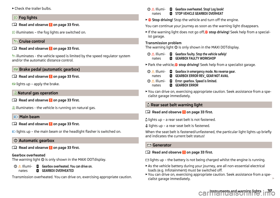
▶Check the trailer bulbs.
Fog lights
Read and observe
on page 33 first.
illuminates – the fog lights are switched on.
Cruise control
Read and observe
on page 33 first.
illuminates - the vehicle speed is limited by the speed regulator system
and/or the automatic distance control.
Brake pedal (automatic gearbox)
Read and observe
on page 33 first.
lights up – apply the brake.
Natural gas operation
Read and observe
on page 33 first.
illuminates - the vehicle is running on natural gas.
Main beam
Read and observe
on page 33 first.
lights up – the main beam or the headlight flasher is switched on.
Automatic gearbox
Read and observe
on page 33 first.
Gearbox overheated
The warning light is only shown in the MAXI DOTdisplay.
Illumi-
nates
Gearbox overheated. You can drive on.GEARBOX OVERHEATED
Transmission overheated. You can drive on, exercising appropriate caution.
Illumi-
nates
Gearbox overheated. Stop! Log book!STOP VEHICLE GEARBOX OVERHEAT
▶ Stop driving! Stop the vehicle and turn off the engine.
You can continue your journey as soon as the warning light disappears.
▶ If the warning light does not go off,
stop driving! Seek help from a special-
ist garage.
Transmission problem
The warning light
is only shown in the MAXI DOTdisplay.
Illumi-
nates
Gearbox faulty. Stop the vehicle safely!GEARBOX FAULTY WORKSHOP
▶ Park the vehicle,
stop driving! Seek help from a specialist garage.
Illumi-
nates
Gearbox in emergency mode. No reverse gear.GEARBOX ERROR REV_ GEAR NOT AVAIL Illumi-
nates
Error: gearbox. Speed is limited.GEARBOX ERROR
▶ You can drive on, exercising appropriate caution. Seek assistance from a spe-
cialist garage immediately.
Rear seat belt warning light
Read and observe
on page 33 first.
lights up – a rear seat belt is not fastened.
lights up – a rear seat belt is fastened.
When the seat belt is fastened/unfastened, the particular light lights up briefly
and indicates the current belt status!
Generator
Read and observe
on page 33 first.
lights up – the battery is not being charged whilst the engine is running.
▶ As the vehicle battery during your journey, are all non-essential electrical
loads (e.g. Infotainment) must be switched off.
▶ You can drive on, exercising appropriate caution. Seek assistance from a spe-
cialist garage immediately.
37Instruments and warning lights
Page 57 of 324
MalfunctionsRead and observe
and on page 51 first.
Synchronising the remote control
If the buttons on the remote control key have been depressed several times
beyond the effective range of the equipment or the battery has been replaced
in the remote control key and the vehicle cannot be unlocked with the remote
control, the key must be synchronised.
›
Press any button on the remote control key.
›
Unlock the door with the key via the lock cylinder within 1 minute of pressing
the button.
Fault with the central locking
If the warning light in the driver's door initially flashes quickly for around 2 sec-
onds, and then illuminates for 30 seconds without interruption before flashing
again slowly, you will need to seek the assistance of a specialist garage.
A failure in the central locking system can lead the vehicle doors and the boot
lid can emergency lock or emergency release » page 276.
Failure of the system KESSY
If there is a fault in the KESSY system, the appropriate error message is dis-
played in the instrument cluster.
Low voltage of the key battery
If the voltage of the key battery is too low, a message appears in the display of the instrument cluster referring to the need to replace the battery. Replace
the battery » page 275.
Anti-theft alarm system
Introduction
This chapter contains information on the following subjects:
Alarm trigger
55
Interior monitor and towing protection
56
The alarm system triggers audible and visual signals if an attempt is made to
break into the vehicle (hereafter referred to as alarm).
The alarm system is activated automatically approximately 30 seconds after the vehicle is locked. This is automatically disabled after release.
CAUTIONBefore leaving the vehicle, it must be checked that all of the windows, doors
and the sliding/tilting roof are locked in order to ensure the full functionality of
the anti-theft alarm system.
Note
The alarm system has its own power source, the service life of which is 5 years.
In order to ensure functionality of the alarm system, we recommend that you
get the alarm checked after this time by a specialist garage.
Alarm trigger
Read and observe
on page 55 first.
The alarm is triggered when one of the following unauthorised actions is acti-
vated on the vehicle with an activated warning system. ▶ Opening the bonnet.
▶ Opening the boot lid.
▶ Opening the doors.
▶ Manipulation of the ignition lock.
▶ Towing the vehicle.
▶ Movement in the vehicle.
▶ Sudden and significant voltage drop of the electrical system.
▶ Uncoupling the trailer.
An alarm is triggered also when the driver's door is unlocked and opened by
the lock cylinder.
The alarm is switched off by pressing the
button on the key or switching on
the ignition.
55Unlocking and opening
Page 59 of 324
NoteButtonA » Fig. 38 is disabled when starting off or driving at a speed of over 5
km/h. The button is reactivated when the vehicle has stopped and a door is
opened.
Delayed locking of the boot lid
Read and observe
on page 56 first.
If the boot lid is unlocked with the button on the key, then the boot lid is
automatically locked after closing.
The period after which the boot lid is locked automatically can be extended by
a specialist garage.
CAUTION
There is a risk of unwanted entry into the vehicle before the boot lid is locked
automatically.
Electric boot lid
Introduction
This chapter contains information on the following subjects:
Description of operation
58
Set the top position of the lid
58
Malfunctions
58
The boot lid (hereinafter referred to as lid) can be operated electrically and
manually in the event of an emergency » page 58.
WARNING■
Ensure that the lock is properly engaged after closing the lid. Otherwise,
the lid might open suddenly while the vehicle is moving, even if the lid was
locked – There is a risk of an accident!■
Never drive with the lid open or unlatched, as otherwise exhaust gases
may get into the interior of the vehicle – risk of poisoning!
■
Only open and close the lid when no one is located in the opening/closing
range – risk of injury!
WARNING (Continued)■ Make sure that when closing the lid, no body parts are crushed – risk of
injury!■
When you open the boot lid make sure that there are no persons in the
opening area of the lid - there is a danger of injury!
CAUTION
Do not attempt to close the lid manually during the electrical closing process -
there is a risk of damaging the electric lid operation.
CAUTION
■ Check that no objects are located in the opening/closing area which could
hinder the movement (e.g. cargo on the roof rack or on the trailer etc.) - there
is a risk of damage to the lid!■
In certain circumstances, if the lid is loaded (e.g by a thick layer of snow), the
opening process of the lid can be interrupted. Remove the snow from the lid to
re-enable the electrical operation.
■
If the lid closes automatically (e.g. under load of snow), you will hear an inter-
mittent beep.
■
Always close the flap before disconnecting the battery.
57Unlocking and opening
Page 70 of 324
NoteWhile driving with an accessory connected to the trailer socket (e.g. trailer,
bike carrier) only the equipment is illuminated by the fog light. The towing de-
vice must be installed at the factory or from the ŠKODA original accessories.
Fog lights with CORNER function
Read and observe
on page 64 first.
The CORNER function automatically switches on the fog lights on the respec-tive side of the vehicle (e.g. when cornering), if the following conditions are
met.
The turn signal is switched on or the front wheels are turned sharply 1)
.
The vehicle speed is below 40 km/h.
The low beam is switched on.
The fog lights are not switched on.
The two fog lights are switched on when you shift into the reverse gear.
COMING HOME / LEAVING HOME
Read and observe
on page 64 first.
The function COMING HOME ensures that the vehicle's environment is illumi-
nated after switching off the ignition and opening the driver's door.
The function LEAVING HOME ensures that the vehicle's environment is illumi-
nated after unlocking the vehicle with the radio remote control unit.
The function switches the light on only if there is poorer visibility and the light
switch is in the position .
The two functions can be activated/deactivated and set in the Infotainment
menu
→
→
Light
.
CAUTION
■
Poorer visibility is evaluated by a sensor mounted below the windscreen in
the holder of the rear-view mirror. Do not cover the sensor - the system can be
affected.■
If this option is always enabled, then the battery is heavily loaded.
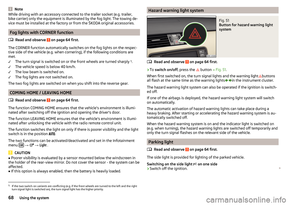
Hazard warning light systemFig. 51
Button for hazard warning light
system
Read and observe on page 64 first.
›
To switch on/off , press the
button
» Fig. 51 .
When first switched on, the turn signal lights and the warning light buttons
all flash at the same time as the warning lights
in the instrument cluster.
The hazard warning light system can also be operated if the ignition is switch-
ed off.
If one of the airbags is deployed, the hazard warning light system will switch
on automatically.
The automatic activation of hazard warning lights can take place during a
heavy braking. After starting or accelerating the hazard warning system is au-
tomatically switched off.
When the hazard warning system is on and the indicator light is switched on
(e.g. when turning), the hazard warning lights are switched off temporarily and
only the turn signal flashes on the relevant side of the vehicle.
Parking light
Read and observe
on page 64 first.
The side light is provided for lighting of the parked vehicle.
Switching on the side light on one side
›
Switch off the ignition.
1)
If the two switch-on variants are conflicting (e.g. if the front wheels are turned to the left and the right
turn signal light is switched on), the turn signal light has the higher priority.
68Using the system
Page 130 of 324

■Forward calls - Setting forwarding of incoming calls (valid for Infotainment Co-
lumbus with the SIM card slot in the external module) ■All calls
- Forward all incoming calls
■
If engaged
- Forwarding incoming calls during a telephone call
■
If not available
- Forwarding the incoming calls when the vehicle is outside
the reach of the telephone service provider signal
■
If no answer
- Redirecting incoming calls when the incoming call is not an-
swered
SmartLink menu settings
›
In the SmartLink main menu, tap on the function surface
.
■
Activate data transfer for ŠKODA apps
- Turning data transfer on and off for ŠKODA
applications
■ MirrorLink® - Settings of the system MirrorLink ®
■
Screen orientation:
- Setting the screen orientation
■
Landscape
- Width display
■
Portrait
- Height display
■
Rotated 180 degrees
- Turn on / off the 180 ° inversion
■
Allow MirrorLink® notification to be shown
- Turn on / off the display of messages
of Mirror link ®
applications on the Infotainment screen
Navigation menu settings
Route options
›
In the Navigation main menu, tap on the function surface
Tap on
→
routeoptions
.
■
Suggest 3 alternative routes
- Switch on/off the menu for alternative routes (eco-
nomical, fast, short)
■
Route:
- Setting the preferred route
■
Most frequent routes
- Show/hide the menu of the most frequent routes in the
split screen
■
Dynamic route
- Switch on/off dynamic route recalculation due to TMC traffic
reports
■
Avoid motorways
- Switch on/off the non-use of motorways in the route cal-
culation
■
Avoid ferries and motorail trains
- Switch on/off the non-use of ferries and mo-
torail trains in the route calculation
■
Avoid toll roads
- Switch on/off use of toll roads for route calculation
■
Avoid tunnels
- Switch on/off use of tunnels for route calculation
■
Avoid routes requiring toll stickers - Switch use of routes requiring toll stickers
on/off for route calculation
■Show available toll stickers
- Selection of countries for which a valid toll sticker is
required (routes requiring toll stickers are used for route calculation)
■
Include trailer
- Turn on / off the setting to take a trailer into account for
route calculation » page 180
Map
›
In the Navigation main menu, tap on the function surface
Tap on →
Map
.
■
Show road signs
- Switch on/off the display of traffic signs
■
Lane guidance
- Display of lane guidance on/off
■
Show favourites
- Switch on/off the display of favourites
■
Show POIs
- Switch on/off the display of POIs
■
Select categories for POIs
- Selection of the displayed category POIs
■
Show brands for POIs
- Switch on/off the company logos available for the POIs
shown
Manage memory
›
In the Navigation main menu, tap on the function surface
→
Manage memo-ry
.
■
Sort Contacts:
- Setting the arrangement of the phonebook
■
By surname
- Sorting by the contact surname
■
By first name
- Sorting by the contact first name
■
Define home address
- Enter the home address
■
Delete My POIs
- Deleting own POI categories (Personal POI)
■
Update My POIs (SD / USB)
- Import / update your own POI categories (Personal
POI)
■
Import destinations (SD/USB)
- Import destinations in vCard format
■
Delete user data
- Delete user data (by pressing the function surface
Delete
and
confirm the deletion) ■
Last destinations
- Delete the last destinations
■
Dest. memory
- Delete the stored destinations
■
Routes
- Delete saved routes
■
My points of interest (Personal POI)
- Delete the custom POIs
■
Entered cities
- Delete the history of places already entered via the address
■
Home address
- Delete the stored home address
■
Flagged destination
- Delete the flagged destination
128Infotainment
Page 181 of 324
For trailer towing , We recommend that you activate recognition of road signs
relevant to trailers.›
Press the button, then tap on the function surface
→
Driver assistance
→
Show road signs relevant to trailers
.
Route guidance
Introduction to the subject
A route is created by starting route guidance to a destination. Additional inter-
mediate destinations can be added to the route.
The route guidance takes place as follows
▶ Through graphical driving instructions on the Infotainment screen and in the
display of the instrument cluster.
▶ With nav. announcements.
Infotainment tries to allow for continued guidance even if the navigation data
is incomplete or there is no data at all for the given area.
The route is recalculated each time if you ignore driving recommendations or change the route.
CAUTION
The nav. announcements provided may vary from the actual situations, e.g.
due to out-of-date navigation data.
Destination details
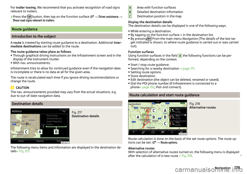
Fig. 217
Destination details
The following menu items and information are displayed in the destination de-
tails » Fig. 217 .
Area with function surfaces
Detailed destination information
Destination position in the map
Display the destination details
The destination details can be displayed in one of the following ways.
▶ While entering a destination.
▶ By tapping on the function surface
in the destination list.
▶ By pressing
From the main menu
Navigation (The details of the last tar-
get indicated is shown, to where route guidance is carried out or was carried
out).
Function surfaces
Using function surfaces in the field
A
the following functions can be per-
formed, depending on the context.
▶ Start / stop route guidance.
▶ Searching for a nearby destination » page 171.
▶ Setting route options.
▶ Store destination.
▶ Edit destination (the object can be deleted, renamed or saved).
▶ Dial the POI phone number (if Infotainment is connected to a
phone » page 152 , Pair and connect ).
Route calculation and start route guidance
Fig. 218
Alternative routes
Route calculation is done on the basis of the set route options. The route op-
tions can be set:
→
Route options
.
Alternative routes
With selection of alternative routes turned on, the following menu is displayed
after the calculation of a new route » Fig. 218.
ABC179Navigation