technical data SKODA OCTAVIA TOUR 2011 2.G / (1Z) Owner's Guide
[x] Cancel search | Manufacturer: SKODA, Model Year: 2011, Model line: OCTAVIA TOUR, Model: SKODA OCTAVIA TOUR 2011 2.G / (1Z)Pages: 183, PDF Size: 11.13 MB
Page 62 of 183
Seats and Stowage61
Using the system
Safety
Driving Tips
General Maintenance
Breakdown assistance
Technical Data
WARNING
•
Take care when using the cigarette lighter! Not paying proper attention or
incorrect use the cigarette lighter in an uncontrolled manner may result in burns.
•
The cigarette lighter and the power socket also operates when the ignition
is switched off or the ignition key withdrawn. You should therefore never leave
children unattended in the vehicle.Caution
Always use matching plugs to avoid damaging the power socket.
Note
•
Connecting electrical components when the engine is not running will drain
the battery of the vehicle - risk of battery draining!
•
Further information page 146, “Accessories, changing and replacing parts”.
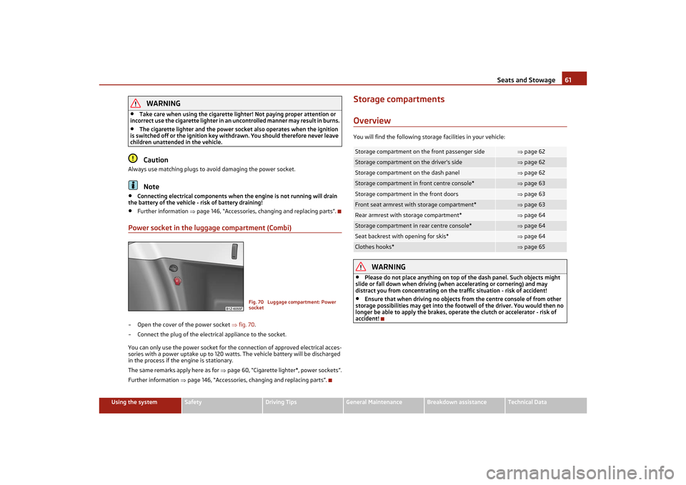
Power socket in the luggage compartment (Combi)– Open the cover of the power socket fig. 70.
– Connect the plug of the electrical appliance to the socket.
You can only use the power socket for the connection of approved electrical acces-
sories with a power uptake up to 120 watts. The vehicle battery will be discharged
in the process if the engine is stationary.
The same remarks apply here as for page 60, “Cigarette lighter*, power sockets”.
Further information page 146, “Accessories, changing and replacing parts”.
Storage compartmentsOverviewYou will find the following storage facilities in your vehicle:
WARNING
•
Please do not place anything on top of the dash panel. Such objects might
slide or fall down when driving (when accelerating or cornering) and may
distract you from concentrating on the traffic situation - risk of accident!
•
Ensure that when driving no objects from the centre console of from other
storage possibilities may get into the footwell of the driver. You would then no
longer be able to apply th e brakes, operate the clutch or accelerator - risk of
accident!
Fig. 70 Luggage compartment: Power
socket
Storage compartment on the front passenger side
page 62
Storage compartment on the driver's side
page 62
Storage compartment on the dash panel
page 62
Storage compartment in front centre console*
page 63
Storage compartment in the front doors
page 63
Front seat armrest with storage compartment*
page 63
Rear armrest with storage compartment*
page 64
Storage compartment in rear centre console*
page 64
Seat backrest with opening for skis*
page 64
Clothes hooks*
page 65
s2lk.2.book Page 61 Monday, April 18, 2011 7:41 AM
Page 64 of 183
Seats and Stowage63
Using the system
Safety
Driving Tips
General Maintenance
Breakdown assistance
Technical Data
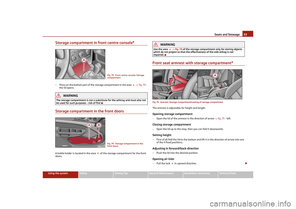
Storage compartment in front centre console*– Press on the bottom part of the storage compartment in the area fig. 73 -
the lid opens.
WARNING
The storage compartment is not a substitu te for the ashtray and must also not
be used for such purposes - risk of fire!Storage compartment in the front doorsA bottle holder is located in the area of the storage compartment for the front
doors.
WARNING
Use the area fig. 74 of the storage compartment only for storing objects
which do not project so that the effe ctiveness of the side airbag is not
impaired.Front seat armrest with storage compartment*Fig. 75 Armrest: Storage compartm ent/cooling of storage compartmentThe armrest is adjustable for height and length.Opening storage compartment– Open the lid of the armrest in the direction of arrow fig. 75 - left.Closing storage compartment– Open the lid up to the stop, then you can fold it downwards.Setting height– First of all fold the lid to the bottom and lift it in the direction of arrow into one
of the 4 fixed positions.Adjusting in forward/back direction– Push the lid into the desired position.Opening air inlet– Pull the lock in upward direction.
Fig. 73 Front centre console: Storage
compartment
A
Fig. 74 Storage compartment in the
front doors
B
AA
s2lk.2.book Page 63 Monday, April 18, 2011 7:41 AM
Page 66 of 183
Seats and Stowage65
Using the system
Safety
Driving Tips
General Maintenance
Breakdown assistance
Technical Data
Opening from passenger compartment– Pull down the armrest of the rear seat at the loop page 52.
– Pull the handle up to the stop in upward direction and fold open the lid down- wards page 64, fig. 78 - left.Opening from luggage compartment– Push the unlock button downwards page 64, fig. 78 - right and fold the lid
(with armrest) to the front.Closing– Fold the cover and the arm rest upwards as far as the stop. The cover must click
into place audibly.
Ensure that the armrest is always locked into place after closing. You can recognise
this on the fact that the red field above the unlocking button of the luggage
compartment is not visible.Clothes hooks*The clothes hooks are located on the middle pillar and on the handle in the head-
liner above each of the rear doors.
WARNING
•
Ensure that any clothes hanging from the hooks do not impair your vision to
the rear.
•
Use the hooks for hanging only light items of clothing and ensure that there
are no heavy or sharp-edge d objects in the pockets.
•
The maximum permissible load of the hooks is 2 kg.
•
Do not use clothes hangers for hanging up items of clothing otherwise this
will interfere with the protecti on offered by the head airbag*.
s2lk.2.book Page 65 Monday, April 18, 2011 7:41 AM
Page 68 of 183
Heating and air conditioning system67
Using the system
Safety
Driving Tips
General Maintenance
Breakdown assistance
Technical Data
HeatingUsing the system
The heating system delivers air into the interior of the vehicle and
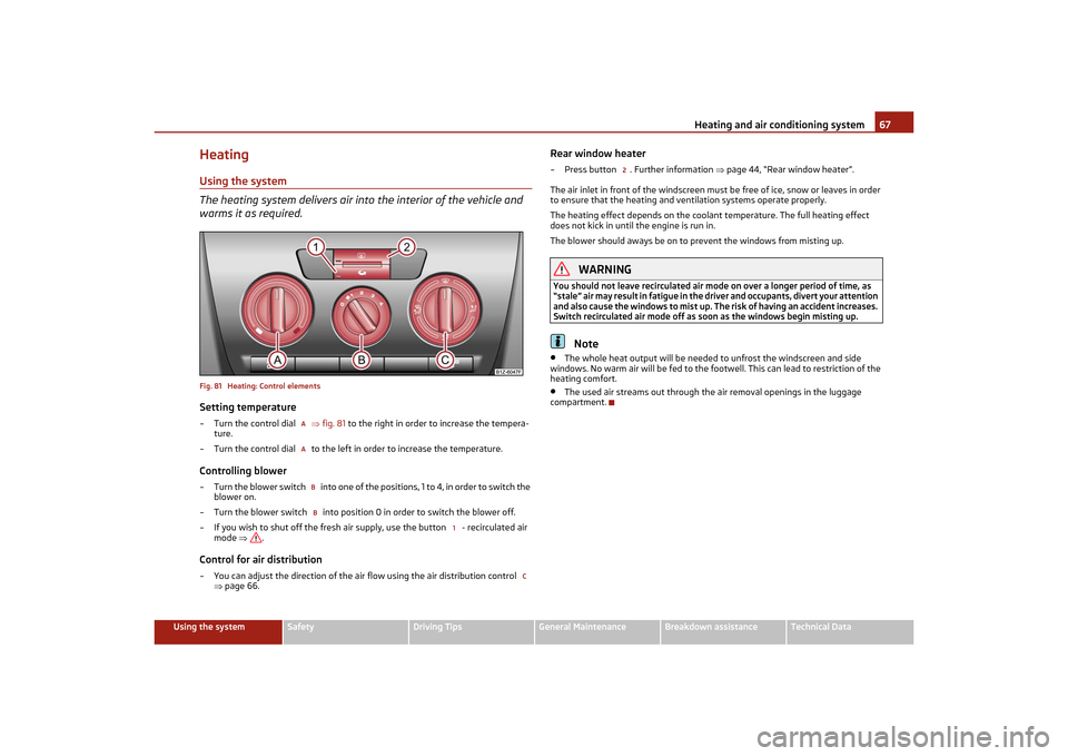
warms it as required.Fig. 81 Heating: Control elementsSetting temperature– Turn the control dial fig. 81 to the right in order to increase the tempera-
ture.
– Turn the control dial to the left in order to increase the temperature.Controlling blower– Turn the blower switch into one of the po si ti o ns , 1 to 4, in o rd e r t o sw itc h the
blower on.
– Turn the blower switch into position 0 in order to switch the blower off.
– If you wish to shut off the fresh air su pply, use the button - recirculated air
mode .Control for air distribution– You can adjust the direction of the air flow using the air distribution control
page 66.
Rear window heater– Press button . Further information page 44, “Rear window heater”.
The air inlet in front of the windscreen must be free of ice, snow or leaves in order
to ensure that the heating and ve ntilation systems operate properly.
The heating effect depends on the coolan t temperature. The full heating effect
does not kick in until the engine is run in.
The blower should aways be on to prevent the windows from misting up.
WARNING
You should not leave recirculated air mode on over a longer period of time, as
“stale” air may result in fatigue in the dr iver and occupants, divert your attention
and also cause the windows to mist up. Th e risk of having an accident increases.
Switch recirculated air mode off as soon as the windows begin misting up.
Note
•
The whole heat output will be needed to unfrost the windscreen and side
windows. No warm air will be fed to the footwell. This can lead to restriction of the
heating comfort.
•
The used air streams out through the air removal openings in the luggage
compartment.
AABB
1
C
2
s2lk.2.book Page 67 Monday, April 18, 2011 7:41 AM
Page 70 of 183
Heating and air conditioning system69
Using the system
Safety
Driving Tips
General Maintenance
Breakdown assistance
Technical Data
Recirculated air mode
In recirculated air mode air is sucked out of the interior of the vehicle
and then fed back into the interior.Recirculated air mode prevents polluted ai r outside the vehicle from getting into the
vehicle, for example when driving through a tunnel or when standing in a traffic jam.Switching recirculated air mode on– Press the button . The warning light in the button page 67, fig. 81 goes
out.Switching recirculated air mode off– Once again press the button . The warning light in the button goes out.
The recirculated air mode is switched off au tomatically if the air distribution control
is in position
page 67, fig. 81 . You can also switch recirculated air mode on
again from this setting by re peatedly pressing pushbutton .
WARNING
You should not leave recirculated air mode on over a longer period of time, as
“stale” air may result in fatigue in the driver and occupants, divert your attention
and also cause the windows to mist up. Th e risk of having an accident increases.
Switch recirculated air mode off as soon as the windows begin misting up.Climatic*Description
The Climatic is a combined cooling and heating system. It makes it
possible to optimally control the air temperature at any season of
the year.Description of the Climatic
It is important for your safety and for your driving comfort that the Climatic is oper-
ating properly.
The cooling only op erates if button page 70, fig. 82 is pressed, and the
following conditions are met:
•
engine running,
•
outside temperature above approx. +2 °C and
•
blower switch switched on (positions 1 to 4).
If the cooling system is switched on, the temperature and air humidity drops in the
vehicle. The wellbeing of the occupants of the car is enhanced as a result of this
particularly at high outside temperatur es and a high air humidity. The system
prevents the windows misting up during the cold season of the year.
The heating effect depends on the coolan t temperature. The full heating effect
does not kick in until the engine is run in.
It is possible to briefly activate recirculated air mode in order to enhance the cooling
effect .
Air at a temperature of about 5 °C may fl ow out of the vents under certain circum-
stances when the cooling system is operat ing. Lengthy and uneven distribution of
the air flow out of the vents and large differences in temperature, for example when
getting out of the vehicle, can resu lt in chills in sensitive persons.
The air inlet in front of the windscreen must be free of ice, snow or leaves in order
to ensure that the heating and cooling systems operate properly.
After switching on the cooling Condensation from the evaporator of the air condi-
tioning may drip down and form a puddle below the vehicle. This is quite normal and
not an indication of a leak!
WARNING
•
For your own safety and that of othe r road users, ensure that all the
windows are free of ice, snow and mistin g. Please familiarize yourself about how
to correctly operate the heating and ve ntilation systems, how to demist and
defrost the windows, as well as with the cooling mode.
•
You should not leave recirculated air mo de on over a longer period of time,
as “stale” air may result in fatigue in the driver and occupants, divert your atten-
tion and also cause the windows to mist up. The risk of having an accident
increases. Switch recirculated air mode off as soon as the windows begin
misting up.Note
•
We recommend that you do not smoke in the vehicle when the recirculating air
mode is operating since the smoke which is drawn at the evaporator from the inte-
rior of the vehicle forms deposits in the evaporator of the air conditioning system.
This produces a permanent odour when th e air conditioning system is operating
C
AC
2
s2lk.2.book Page 69 Monday, April 18, 2011 7:41 AM
Page 72 of 183
Heating and air conditioning system71
Using the system
Safety
Driving Tips
General Maintenance
Breakdown assistance
Technical Data
Set ClimaticRecommended settings of Climatic controls for the respective operating modes:
Setup
Setting of the control dial
Button
Air outlet vents 3
Defrosting the windscreen and
side windows
To the right up to
the stop
3
Switched off
Do not switch on
Open and align with the side window
Free windscreen and side win-
dows from mist
Desired tempera-ture
2 or 3
switched on
Do not switch on
Open and align with the side window
The fastest heating
To the right up to the stop
3
Switched off
briefly switched on
Opening
Comfortable heating
Desired tempera- ture
2 or 3
Switched off
Do not switch on
Opening
the fastest cooling
T o t h e l e f t u p t o t h e stop
briefly 4, then 2or 3
switched on
briefly switched on
Opening
optimal cooling
Desired tempera- ture
1, 2 or 3
switched on
Do not switch on
open and align to the roof
Fresh air mode - ventilation
T o t h e l e f t u p t o t h e stop
Desired position
Switched off
Do not switch on
Opening
A
B
C
2
3
s2lk.2.book Page 71 Monday, April 18, 2011 7:41 AM
Page 74 of 183
Starting-off and Driving73
Using the system
Safety
Driving Tips
General Maintenance
Breakdown assistance
Technical Data
Starting-off and DrivingSetting steering wheel positionFig. 83 Adjustable steering wheel: Lever below steering columnYou can set the height and the forward/back position of the steering wheel to the
desired position.
– Adjust the driver seat page 11.
– Pull the lever below the steering column down fig. 83 - left. Observe the
guidelines .
– Set the steering wheel to the desired position (concerning height and forward/back position).
– Push the lever upwards as far as the stop.
WARNING
•
You must not adjust the steering wheel when the vehicle is moving!
•
The driver must maintain a distance of at least 25 cm to the steering wheel
fig. 83 - right. Not maintaining this minimum distance will mean that the
airbag system will not be able to properly protect you - hazard!
•
For safety reasons the lever must always be firmly pushed up to avoid the
steering wheel altering its position unin tentionally when driving - risk of acci-
dent!
•
If you adjust the steering wheel further towards the head, you will reduce
the protection offered by the driver airbag in the event of an accident. Make sure
the steering wheel is aligned to the chest.
•
When driving, hold the steering wheel with both hands firmly on the outer
edge in the 9 o'clock and 3 o'clock positi on. Never hold the steering wheel firmly
in the 12 o'clock position or in another way (e.g. in the middle of the steering
wheel or at the inner steering wheel edge). In such cases, injuries to the arms,
the hands and the head can occur when the driver airbag is deployed.
Ignition lockPetrol engines
- ignition switched off, engine off, the steering can be locked.
- ignition switched on
- start engine
Diesel engines - interruption of fuel suppl y, ignition switched off, engine off, the steering can
be locked.
- heating glow plugs on, ignition switched on•
You should not switch on any major elec trical components during the heating
period. Otherwise the vehicle battery will be drained unnecessarily.
- start engineWARNING (continued)
Fig. 84 Ignition lock positions
123123
s2lk.2.book Page 73 Monday, April 18, 2011 7:41 AM
Page 76 of 183
Starting-off and Driving75
Using the system
Safety
Driving Tips
General Maintenance
Breakdown assistance
Technical Data
Petrol enginesThese engines are fitted with a starter system which selects the correct fuel-air
mixture for every external air temperature.•
Do not operate accelerator before and when starting engine.
•
Interrupt the attempt at star ting after 10 seconds if the engine does not start
right away and wait for about 30 seconds before repe ating the attempt.
•
It is possible that the fuse on the electrical fuel pump is defect if the engine still
does not start. Check the fuse and replace it if necessary page 156.
•
Contact the nearest specialist garage to obtain professional assistance.
It may be necessary, if the engine is very hot, to slightly depress the accelerator
after the engine has started.
Diesel enginesGlow plug system
Diesel engines are equipped with a glow plug system, the preglow period being
controlled automatically in line with the coolant temperature and outside tempera-
ture.
The preglow indicator light
comes on after the ignition has been switched on.
You should not switch on any major elec trical components during the heating
period otherwise the vehicle battery will be drained unnecessarily.
•
You should start the engine immediately after the glow plug warning light
has gone out.
•
The glow plug warning light will come on for about one second if the engine is
at a normal operating temperature or if th e outside temperature is above +5 °C. This
means that you can start the engine right away .
•
Interrupt the attempt at starting after 10 seconds if the engine does not start
right away and wait for about 30 seconds before repe ating the attempt.
•
It is possible that the fuse on the diesel preglow system is defect if the engine
still does not start. Check the fuse and replace it if necessary page 156.
•
Contact the nearest specialist garage to obtain professional assistance.
Starting the engine after the fuel tank has run dry
It may take longer than normal to start the engine after refuelling if the fuel tank
has run completely dry - up to one minute. This is because the fuel system must first
of all be filled while the attempting to start the engine.
Switching off the engine– The engine can be switched off by tur ning the ignition key into position
page 73, fig. 84 .
WARNING
•
Never switch off the engine before the ve hicle is stationary - risk of accident!
•
The brake booster only operates when the engine is running. Greater phys-
ical effort for braking is required when en gine is switched off. Because if you do
not stop as normal, this can caus e an accident and severe injuries.Caution
you should not switch the engine off right away at the end of your journey after the
engine has been operated for a lengthy period at high loads but should be allowed
it to run at idling speed for about 2 minutes . This prevents any accumulation of heat
when the engine is switched off.
Note
•
The radiator fan may continue running for a further 10 minutes or so after the
engine and the ignition have been switched off. The coolant fan may, however, also
switch on again after some time if the coolant temperature rises because of an
a c c um ul a tio n o f he a t i n the en g in e o r i f the engine is warm and the engine compart-
ment is additionally heat ed by strong sunlight.
•
This is why particular care is required when carrying out any work in the engine
compartment page 131, “Working in the engine compartment”.
1
s2lk.2.book Page 75 Monday, April 18, 2011 7:41 AM
Page 78 of 183
Starting-off and Driving77
Using the system
Safety
Driving Tips
General Maintenance
Breakdown assistance
Technical Data
Caution
Each time the vehicle is parked, first of all apply the handbrake and then additionally
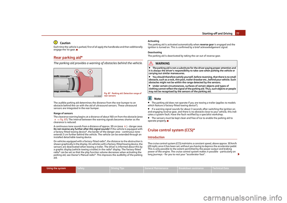
engage the 1st gear.Rear parking aid*The parking aid provides a warnin g of obstacles behind the vehicle.The audible parking aid determines the distance from the rear bumper to an
obstacle behind the car with the aid of ultrasound sensors. These ultrasound
sensors are integrated in the rear bumper.
Range of sensors
The clearance warning begins at a distance of about 160 cm from the obstacle (area
fig. 87 ). The interval between the warning signals becomes shorter as the
clearance is reduced.
A continuous tone sounds from a distance of approx. 30 cm (area ) - danger area.
Do not reverse any further after this signal sounds! If the vehicle is equipped with
a factory-fitted towing device*, the border of the danger area - continuous tone -
extends 5 cm further behind the vehicle. The vehicle can be extended through an
installed detachable towing device.
On vehicles equipped with a factory-fitted radio*, the distance to the obstruction is
shown graphically in the display. On vehicl es with a factory-fitted towing device, the
sensors are deactivated when towing a trailer. The driver is informed about this by
a graphic display (vehicle towing a trailer) in the radio* display. The factory-fitted
radio* can be set so that the play function volume decreases when activating the
parking aid, see Owner's Manual radio*. This improves the audibility of the parking
aid. Activating
The parking aid is activated automatically when
reverse gear is engaged and the
ignition is turned on. This is confirmed by a brief acknowledgement signal.
Deactivating
The parking aid is deactivated by taking the car out of reverse gear.
WARNING
•
The parking aid is not a substitute for the driver paying proper attention and
it is always the driver's responsibility to take care when parking the vehicle or
carrying out similar manoeuvres.
•
You should therefore satisfy yourself, before reversing, that there is no small
obstacle, such as a rock, thin post, traile r drawbar etc., behind your vehicle. Such
obstacles might not be within the range detected by the sensors.
•
Under certain circumstances, surfaces of certain objects and types of
clothing cannot reflect the signal of the pa rking aid. Thus, such objects or people
may not be recognised by the sensors of the parking aid.Note
•
The parking aid does not operate if you are towing a trailer (applies to models
which feature a factory-fitted towing device*).
•
If a warning signal sounds for about 3 seconds after switching the ignition on
and engaging reverse gear, and there is no obstacle close to your vehicle, this indi-
cates a system fault. Have the fault rectified by a specialist workshop.
•
The sensors must be kept clean and free of ice to enable the parking aid to
operate properly.
Cruise control system (CCS)*IntroductionThe cruise control system (CCS) maintains a constant speed, above approx. 30 km/h
(20 mph), once it has been set, without yo u having to depress the accelerator pedal.
This is only possible to the extent pe rmitted by the power output and braking
power of the engine. The cruise control syst em makes it possible - particularly on
long journeys - for you to rest your “accelerator foot”.
Fig. 87 Parking aid: Detection range of
rear sensors
A
B
s2lk.2.book Page 77 Monday, April 18, 2011 7:41 AM
Page 80 of 183
Starting-off and Driving79
Using the system
Safety
Driving Tips
General Maintenance
Breakdown assistance
Technical Data
Switching off the cruise control system temporarily–You can switch off temporarily the cruise control syst em, if you depress the
brake or clutch pedal.
– You can switch off temporarily the cruise control system, if you press the switch
in the middle position.
The set speed remains stored in the memory.
You can resume the stored speed by releasing the brake or clutch pedal and by
pressing the button page 78, fig. 88 in the position RES.
WARNING
First ensure that it is not too high for the traffic conditions which exist at that
moment before resuming the stored speed.Switching off the cruise control system completely– Press the switch page 78, fig. 88 to the right into position OFF.
A
BA
s2lk.2.book Page 79 Monday, April 18, 2011 7:41 AM