engine SKODA RAPID 2013 1.G Repair Manual
[x] Cancel search | Manufacturer: SKODA, Model Year: 2013, Model line: RAPID, Model: SKODA RAPID 2013 1.GPages: 226, PDF Size: 15.16 MB
Page 176 of 226
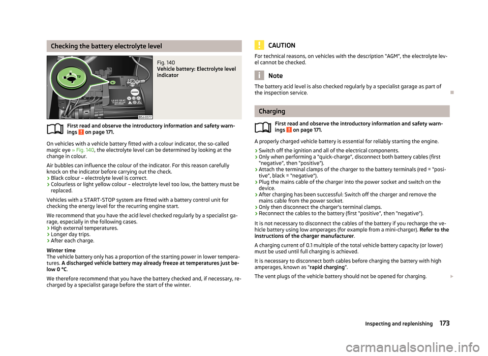
Checking the battery electrolyte levelFig. 140
Vehicle battery: Electrolyte level
indicator
First read and observe the introductory information and safety warn-
ings on page 171.
On vehicles with a vehicle battery fitted with a colour indicator, the so-called
magic eye » Fig. 140, the electrolyte level can be determined by looking at the
change in colour.
Air bubbles can influence the colour of the indicator. For this reason carefully
knock on the indicator before carrying out the check.
› Black colour – electrolyte level is correct.
› Colourless or light yellow colour – electrolyte level too low, the battery must be
replaced.
Vehicles with a START-STOP system are fitted with a battery control unit for checking the energy level for the recurring engine start.
We recommend that you have the acid level checked regularly by a specialist ga-
rage, especially in the following cases.
› High external temperatures.
› Longer day trips.
› After each charge.
Winter time
The vehicle battery only has a proportion of the starting power in lower tempera-
tures. A discharged vehicle battery may already freeze at temperatures just be-
low 0 °C .
We therefore recommend that you have the battery checked and, if necessary, re-
charged by a specialist garage before the start of the winter.
CAUTIONFor technical reasons, on vehicles with the description “AGM”, the electrolyte lev- el cannot be checked.
Note
The battery acid level is also checked regularly by a specialist garage as part of
the inspection service.
Charging
First read and observe the introductory information and safety warn-ings
on page 171.
A properly charged vehicle battery is essential for reliably starting the engine.
›
Switch off the ignition and all of the electrical components.
›
Only when performing a “quick-charge”, disconnect both battery cables (first
“negative”, then “positive”).
›
Attach the terminal clamps of the charger to the battery terminals (red = “posi- tive”, black = “negative”).
›
Plug the mains cable of the charger into the power socket and switch on the
device.
›
After charging has been successful: Switch off the charger and remove themains cable from the power socket.
›
Only then disconnect the charger's terminal clamps.
›
Reconnect the cables to the battery (first “positive”, then “negative”).
It is not necessary to disconnect the cables of the battery if you recharge the ve-
hicle battery using low amperages (for example from a mini-charger). Refer to the
instructions of the charger manufacturer .
A charging current of 0.1 multiple of the total vehicle battery capacity (or lower) must be used until full charging is achieved.
It is necessary to disconnect both cables before charging the battery with high
amperages, known as “ rapid charging”.
The vent plugs of the vehicle battery should not be opened for charging.
173Inspecting and replenishing
Page 177 of 226
WARNING“Quick-charging” the vehicle battery is dangerous and requires a special
charger and specialist knowledge.
CAUTION
On vehicles with the START/STOP system, the pole terminal of the charger must
not be connected directly to the negative terminal of the vehicle battery, but only
to the engine earth » page 191, Jump-starting in vehicles with the START-STOP
system .
Note
We therefore recommend that vehicle batteries be rapid charged by a specialist
garage.
Replacing
First read and observe the introductory information and safety warn-
ings
on page 171.
When replacing a battery, the new vehicle battery must have the same capacity,
voltage, amperage and be the same size. Suitable vehicle battery types can be
purchased from a specialist garage.
We recommend having the battery replaced by a specialist garage, where the
new vehicle battery will be installed properly and the original battery will be dis-
posed of in accordance with national regulations.
Disconnecting and reconnecting
First read and observe the introductory information and safety warn-
ings
on page 171.
On disconnecting and reconnecting the vehicle battery, the following functions
are initially deactivated or are no longer able to operate fault-free:
OperationOperating measureEnter the radio/navigation system code num-
ber» User manual of the radio
or » user manual of the naviga-
tion systemSetting the clock» page 13Data in the multifunction display are deleted.» page 25
Note
We recommend having the vehicle checked by a specialist garage in order to en-
sure full functionality of all electrical systems.
Automatic load deactivation
First read and observe the introductory information and safety warn-ings
on page 171.
The vehicle voltage control unit automatically prevents the battery from discharg-
ing when the battery is put under high levels of strain. This manifests itself by the
following.
› The idling speed is raised to allow the generator to deliver more electricity to
the electrical system.
› Where necessary, large convenience consumers such as seat heaters and rear
window heaters have their power limited or are shut off completely in the event
of an emergency.
CAUTION
■ Despite such intervention by the vehicle electric system management, the vehi-
cle battery may be drained. For example, when the ignition is switched on a long
time with the engine turned off or the side or parking lights are turned on during longer parking.■
Consumers that are supplied via a 12-V power socket can cause the vehicle bat-
tery to discharge when the ignition is switched off.
Note
Driving comfort is not impaired by consumers being deactivated. The driver is of-
ten not aware of it having taken place.
174General Maintenance
Page 187 of 226
WARNING■The factory-supplied lifting jack is only intended for your model of vehicle.
Under no circumstances use it to lift heavier vehicles or other loads – risk of
injury!■
Ensure that the vehicle tool kit is safely secured in the boot.
■
Ensure that the box is always secured with the strap.
Changing a wheel
Introduction
This chapter contains information on the following subjects:
Preliminary work
184
Changing a wheel
185
Follow-up work
185
Loosening/tightening wheel bolts
185
Raising the vehicle
186
Securing wheels against theft
186WARNING■ If you are in flowing traffic, switch on the hazard warning light system and
set up the warning triangle at the prescribed distance! The national legal re-
quirements must be observed.■
Park the vehicle as far away as possible from the flow of traffic. Park on as
flat and firm a surface as possible.
■
The following instructions must be followed if the vehicle is subsequently
fitted with tyres or rims that differ from the factory-fitted ones » page 177,
New tyres .
WARNINGObserve the following instructions for lifting the vehicle.■If the wheel has to be changed on a slope, first of all block the opposite
wheel with a stone or similar object to prevent the vehicle from unexpectedly
rolling away.■
Secure the base plate of the lifting jack with suitable means to prevent pos-
sible moving. A soft and slippery ground under the base plate may move the lifting jack, causing the vehicle to fall down. It is therefore always necessary to
place the lifting jack on a solid surface or use a wide and stable base. Use a non-slip base (e.g. a rubber foot mat) if the surface is smooth, such as cobbled
stones, tiled floor, etc.
■
Only attach the lifting jack to the attachment points provided for this pur-
pose.
■
Always raise the vehicle with the doors closed.
■
Never position any body parts, such as arms or legs under the vehicle, while
the vehicle is raised with a lifting jack.
■
Never start the engine when the vehicle is raised – risk of injury.
CAUTION
■ The prescribed tightening torque of the wheel bolts for steel and light alloy
wheels is 120 Nm.■
If the wheel bolts are fastened too tightly, this can cause damage to the anti-
theft wheel bolt or the adapter.
Note
The national legal requirements must be observed when changing a wheel.
Preliminary work
First read and observe the introductory information and safety warn-ings
on page 184.
Always change a wheel on a level surface as far as possible.
The following steps must be carried out before actually changing the wheel:
›
Have all of the occupants get out of the vehicle. While changing a tyre, the oc-
cupants of the vehicle should not stand on the road (they should instead remain
behind a crash barrier).
184Do-it-yourself
Page 188 of 226
›Switch off the engine.›Move the gearshift lever into
Neutral or move the selector lever for the auto-
matic gearbox into position P .›
Firmly apply the handbrake.
›
Uncouple any trailers.
›
Remove the vehicle tool kit » page 183 and the spare wheel » page 179 from
the boot.
Changing a wheel
First read and observe the introductory information and safety warn-
ings
on page 184.
›
Remove the full wheel trim » page 180 or caps » page 180 .
›
First of all slacken the anti-theft wheel bolt and then the other wheel
bolts » page 185 .
›
Jack up the vehicle until the wheel that needs changing is clear of the
ground » page 186 .
›
Unscrew the wheel bolts and place them on a clean surface (cloth, paper, etc.).
›
Remove the wheel carefully.
›
Attach the spare wheel and slightly screw on the wheel bolts.
›
Lower the vehicle.
›
Alternately tighten wheel bolts opposite (diagonally) with the wheel wrench.
Tighten the anti-theft wheel bolt last » page 185.
›
Replace the wheel trim or the caps.
Note
■
All bolts must be clean and must turn easily.■Under no circumstances grease or oil the wheel bolts!■
When fitting unidirectional tyres, ensure that the direction of rotation is cor-
rect » page 178 .
Follow-up work
First read and observe the introductory information and safety warn-
ings
on page 184.
The following steps must also be performed after changing the wheel.
› Stow and attach the replaced wheel in the spare wheel well using a special
bolt » page 179 , Spare wheel .›
Stow the tool kit in the space provided and secure using the band.
›
Check the tyre pressure on the installed spare wheel as soon as possible.
›
Have the tightening torque of the wheel bolts checked with a torque wrench
as soon as possible.
›
Replace the damaged wheel or consult a specialist garage about repair options.
Note
■ If it is determined that the wheel bolts are corroded and difficult to turn when
changing the wheel, the bolts must be replaced before checking the tightening
torque.■
Drive cautiously and only at a moderate speed until the tightening torque has
been checked.
Loosening/tightening wheel bolts
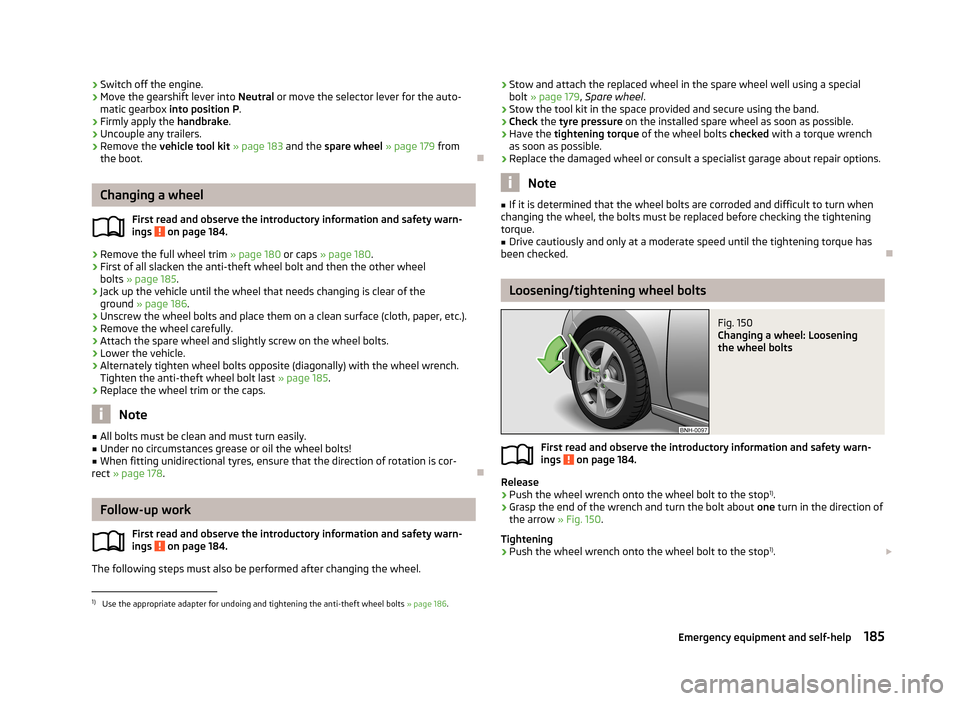
Fig. 150
Changing a wheel: Loosening
the wheel bolts
First read and observe the introductory information and safety warn- ings on page 184.
Release
›
Push the wheel wrench onto the wheel bolt to the stop 1)
.
›
Grasp the end of the wrench and turn the bolt about one turn in the direction of
the arrow » Fig. 150.
Tightening
›
Push the wheel wrench onto the wheel bolt to the stop 1)
.
1)
Use the appropriate adapter for undoing and tightening the anti-theft wheel bolts
» page 186.
185Emergency equipment and self-help
Page 191 of 226
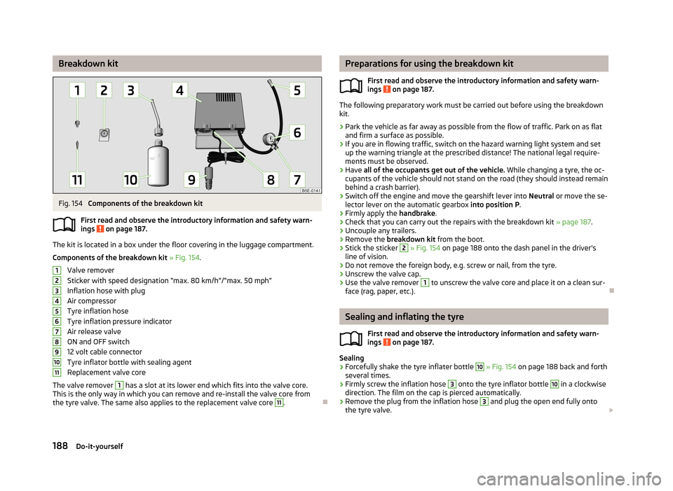
Breakdown kitFig. 154
Components of the breakdown kit
First read and observe the introductory information and safety warn-
ings
on page 187.
The kit is located in a box under the floor covering in the luggage compartment.
Components of the breakdown kit » Fig. 154 .
Valve remover
Sticker with speed designation “max. 80 km/h”/“max. 50 mph”
Inflation hose with plug
Air compressor
Tyre inflation hose
Tyre inflation pressure indicator
Air release valve
ON and OFF switch
12 volt cable connector
Tyre inflator bottle with sealing agent
Replacement valve core
The valve remover
1
has a slot at its lower end which fits into the valve core.
This is the only way in which you can remove and re-install the valve core from
the tyre valve. The same also applies to the replacement valve core
11
.
1234567891011Preparations for using the breakdown kit
First read and observe the introductory information and safety warn-
ings
on page 187.
The following preparatory work must be carried out before using the breakdown kit.
›
Park the vehicle as far away as possible from the flow of traffic. Park on as flat and firm a surface as possible.
›
If you are in flowing traffic, switch on the hazard warning light system and setup the warning triangle at the prescribed distance! The national legal require-
ments must be observed.
›
Have all of the occupants get out of the vehicle. While changing a tyre, the oc-
cupants of the vehicle should not stand on the road (they should instead remain
behind a crash barrier).
›
Switch off the engine and move the gearshift lever into Neutral or move the se-
lector lever on the automatic gearbox into position P.
›
Firmly apply the handbrake.
›
Check that you can carry out the repairs with the breakdown kit » page 187.
›
Uncouple any trailers.
›
Remove the breakdown kit from the boot.
›
Stick the sticker
2
» Fig. 154 on page 188 onto the dash panel in the driver's
line of vision.
›
Do not remove the foreign body, e.g. screw or nail, from the tyre.
›
Unscrew the valve cap.
›
Use the valve remover
1
to unscrew the valve core and place it on a clean sur-
face (rag, paper, etc.).
Sealing and inflating the tyre
First read and observe the introductory information and safety warn-
ings
on page 187.
Sealing
›
Forcefully shake the tyre inflater bottle
10
» Fig. 154 on page 188 back and forth
several times.
›
Firmly screw the inflation hose
3
onto the tyre inflator bottle
10
in a clockwise
direction. The film on the cap is pierced automatically.
›
Remove the plug from the inflation hose
3
and plug the open end fully onto
the tyre valve.
188Do-it-yourself
Page 192 of 226
›Hold the bottle 10 with the bottom facing upwards and fill all of the sealing
agent from the tyre inflator bottle into the tyre.›
Remove the empty tyre inflator bottle from the valve.
›
Screw the valve core back into the tyre valve using the valve remover
1
.
Inflating
›
Screw the air compressor tyre inflation hose
5
» Fig. 154 on page 188 firmly on-
to the tyre valve.
›
Check that the air release valve
7
is closed.
›
Start the engine and run it in idle.
›
Plug the connector
9
into 12 Volt socket » page 60, 12-volt power outlet .
›
Switch on the air compressor with the ON and OFF switch
8
.
›
Allow the air compressor to run until a pressure of 2.0 - 2.5 bar is achieved. Max-
imum run time of 8 minutes » !
›
Switch off the air compressor.
›
If you cannot reach an air pressure of 2.0 – 2.5 bar, unscrew the tyre inflation
hose
5
from the tyre valve.
›
Drive the vehicle 10 metres forwards or backwards to allow the sealing agent to
“distribute” in the tyre.
›
Firmly screw the tyre inflation hose
5
back onto the tyre valve and repeat the
inflation process.
›
If you cannot reach the required tyre inflation pressure here either, this means
the tyre has sustained too much damage. You cannot seal with tyre with the breakdown kit »
.
›
Switch off the air compressor.
›
Remove the tyre inflation hose
5
from the tyre valve.
Once a tyre inflation pressure of 2.0 – 2.5 bar is achieved, continue the journey at
a maximum speed of 80 km/h (50 mph).
Check the tyre inflation pressure after driving for 10 minutes » page 189.
WARNING■
The tyre inflation hose and air compressor may get hot as the tyre is being
inflated – there is a risk of injury.■
Do not place the hot tyre inflation hose or hot air compressor on flammable
materials – there is a risk of fire.
■
If you cannot inflate the tyre to at least 2.0 bar, this means the damage sus-
tained was too serious. The sealing agent cannot be used to seal the tyre.
Do not drive the vehicle. Seek help from a specialist garage.
CAUTIONSwitch off the air compressor after running 8 minutes at the latest – there is a
risk of overheating. Allow the air compressor to cool a few minutes before switch- ing it on again.
Check after 10 minutes' driving
First read and observe the introductory information and safety warn-ings
on page 187.
Check the tyre inflation pressure after driving for 10 minutes!
If the tyre pressure is 1.3 bar or less
›
Do not drive the vehicle! You cannot properly seal with tyre with the break-
down kit.
If the tyre pressure is 1.3 bar or more
›
Adjust the tyre inflation pressure to the correct value (see inside of fuel filler cap).
›
Continue driving carefully to the nearest specialist garage at a maximum speed
of 80 km/h (50 mph).
Jump-starting
Introduction
This chapter contains information on the following subjects:
Jump-starting using the battery from another vehicle
190
Jump-starting in vehicles with the START-STOP system
191WARNING■ A discharged vehicle battery may already freeze at temperatures just below
0 °C. If the battery is frozen, do not jump start with the battery of another ve- hicle – there is a risk of explosion.■
Pay attention to the warning instructions relating to working in the engine
compartment » page 162.
189Emergency equipment and self-help
Page 193 of 226
WARNING (Continued)■The non-insulated parts of the terminal clamps must never touch each other
– there is a risk of short circuit.■
The jump-start cable connected to the positive terminal of the battery must
not come into contact with electrically conducting parts of the vehicle – there
is a risk of short circuit.
■
Do not clamp the jump-start cable to the negative terminal of the dis-
charged battery. There is the risk of detonating gas seeping out the battery
being ignited by the strong spark which results from the engine being started.
■
Route the jump-start cables so that they cannot be caught by any rotating
parts in the engine compartment.
■
Do not bend over the battery – there is a risk of caustic burns.
■
The vent screws of the battery cells must be tightened firmly.
■
Keep any sources of ignition (naked flame, lit cigarettes, etc.) away from the
battery – there is a risk of explosion.
■
Never jump-start vehicle batteries with insufficient acid levels – risk of ex-
plosion and chemical burns.
CAUTION
■ There must not be any contact between the two vehicles otherwise current
may flow as soon as the negative terminals are connected.■
The discharged battery must be properly connected to the system of the vehi-
cle.
■
We recommend you buy jump-start cables from a car battery specialist.
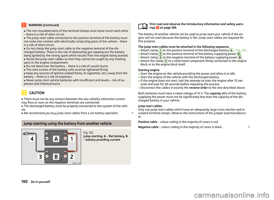
Jump-starting using the battery from another vehicle
Fig. 155
Jump-starting: A – flat battery, B
– battery providing current
First read and observe the introductory information and safety warn-
ings on page 189.
The battery of another vehicle can be used to jump-start your vehicle if the en-
gine will not start because the battery is flat. Jump-start cables are required for
this purpose.
The jump-start cables must be attached in the following sequence.
›
Attach clamp
1
to the positive terminal of the discharged battery
A
» Fig. 155 .
›
Attach clamp
2
to the positive terminal of the battery supplying power
B
.
›
Attach clamp
3
to the negative terminal of the battery supplying power
B
.
›
Attach the clamp
4
to a solid metal component firmly connected to the engine
block or to the engine block itself.
Starting engine
›
Start the engine on the vehicle providing the power and allow it to idle.
›
Start the engine of the vehicle with the discharged battery.
›
If the engine does not start, halt the attempt to start the engine after 10 sec- onds and wait for 30 seconds before repeating the process.
›
Disconnect the cables in exactly the reverse order to the one described above.
Both batteries must have a rated voltage of 12 V. The capacity (Ah) of the battery
supplying the power must not be significantly less than the capacity of the dis-
charged battery in your vehicle.
Jump-start cables
Only use jump-start cables which have an adequately large cross-section and in-
sulated terminal clamps. Observe the instructions of the jumper lead manufactur-
er.
Positive cable – colour coding in the majority of cases is red.
Negative cable – colour coding in the majority of cases is black.
190Do-it-yourself
Page 194 of 226
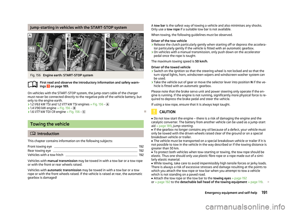
Jump-starting in vehicles with the START-STOP systemFig. 156
Engine earth: START-STOP system
First read and observe the introductory information and safety warn- ings
on page 189.
On vehicles with the START-STOP system, the jump-start cable of the charger must never be connected directly to the negative pole of the vehicle battery, but
only to the engine earth.
› 1.2 l/63 kW TSI and 1.2 l/77 kW TSI engines
» Fig. 156 -
› 1.4 l/90 kW engine
» Fig. 156 -
› 1.6 l/77 kW TDI CR engine
» Fig. 156 -
Towing the vehicle
Introduction
This chapter contains information on the following subjects:
Front towing eye
192
Rear towing eye
192
Vehicles with a tow hitch
192
Vehicles with manual transmission may be towed in with a tow bar or a tow rope
or with the front or rear wheels raised.
Vehicles with automatic transmission may be towed in with a tow bar or a tow
rope or with the front wheels raised. If the vehicle is raised at rear, the automatic
gearbox is damaged!
A tow bar is the safest way of towing a vehicle and also minimises any shocks.
Only use a tow rope if a suitable tow bar is not available.
When towing, the following guidelines must be observed.
Driver of the tow vehicle›
Release the clutch particularly gently when starting off or depress the accelera-
tor particularly gently if the vehicle is fitted with an automatic gearbox.
›
On vehicles with a manual transmission, only push down on the accelerator pedal once the rope is taught.
The maximum towing speed is 50 km/h.
Driver of the towed vehicle
›
Switch on the ignition so that the steering wheel is not locked and so that the turn signal lights, horn, windscreen wipers and windscreen washer system can
be used.
›
Take the vehicle out of gear or move the selector lever into position N if the ve-
hicle is fitted with an automatic gearbox.
Please note that the brake servo unit and power steering only operate if the en-
gine is running. If the engine is not running, significantly more physical force is re- quired to depress the brake pedal and steer the vehicle.
If using a tow rope, ensure that it is always kept taught.
CAUTION
■ Do not tow start the engine – there is a risk of damaging the engine and the
catalytic converter. The battery from another vehicle can be used as a jump-start
aid » page 189 , Jump-starting .■
If the gearbox no longer contains any oil because of a defect, your vehicle must
only be towed with the driven wheels raised clear of the ground or on a special
breakdown vehicle or trailer.
■
The vehicle must be transported on a special breakdown vehicle or trailer if it is
not possible to tow in the vehicle in the way described or if the towing distance is
greater than 50 km.
■
To protect both vehicles when tow-starting or towing, the tow rope should be
elastic. Thus one should only use plastic fibre rope or a rope made out of a simi-
larly elastic material.
■
While towing, take care to avoid impermissibly high tensile forces or jerky loads.
There is always a risk of excessive stresses and damage resulting at the points to
which you attach the tow rope or tow bar when you attempt to tow a vehicle
which is not standing on a paved road.
■
Attach the tow rope or the tow bar to the towing eyes » page 192
or » page 192 to the detachable ball head of the towing equipment » page 119 .
191Emergency equipment and self-help
Page 200 of 226
Fuses and light bulbs
Fuses
Introduction
This chapter contains information on the following subjects:
Fuses in the dash panel
197
Assignment of the fuses in the dash panel
198
Fuses in the engine compartment
199
Fuse assignment in the engine compartment
200
Individual electrical circuits are protected by fuses. Switch off the ignition and the corresponding power consuming device before re-
placing a fuse.
Find out which fuse belongs to the component that is not operating » page 198
or » page 200 .
Fuse colourMaximum amperagelight brown5dark brown7.5red10blue15yellow20white25green30orange40WARNINGAlways read and observe the warning notes before completing any work in
the engine compartment » page 162, Engine compartment .CAUTION■
“Never repair” fuses, and do not replace them with fuses of a higher amperage –
risk of fire! This may also cause damage at other points in the electrical system.■
If a newly inserted fuse blows again after a short time, have the electrical sys-
tem checked as quickly as possible by a specialist garage.
■
A blown fuses is recognisable by the molten metal strip. Replace the faulty fuse
with a new one of the same amperage.
Note
■
We recommend always carrying replacement fuses in the vehicle. A box of re-
placement fuses can be purchased from ŠKODA Original Accessories.■
There can be several power consuming devices for one fuse.
■
There can be several consumer devices for one fuse, depending on the vehicle's
equipment.
■
Multiple fuses may exist for a single power consuming device.
■
Multiple power consuming devices can share a single fuse.
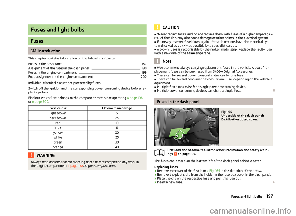
Fuses in the dash panel
Fig. 165
Underside of the dash panel:
Distribution board cover.
First read and observe the introductory information and safety warn-
ings on page 197.
The fuses are located on the bottom left of the dash panel behind a cover.
Replacing fuses
›
Remove the cover of the fuse box » Fig. 165 in the direction of the arrow.
›
Remove the plastic clip from the holder in the fuse box cover in the dash panel.
›
Place the clip on the respective fuse and pull this fuse out.
›
Insert a new fuse.
197Fuses and light bulbs
Page 201 of 226
›Reinsert the cover into the dash panel in the opposite direction to the arrow
such that the guide pins are guided into the dash panel openings.
Carefully push the cover in.
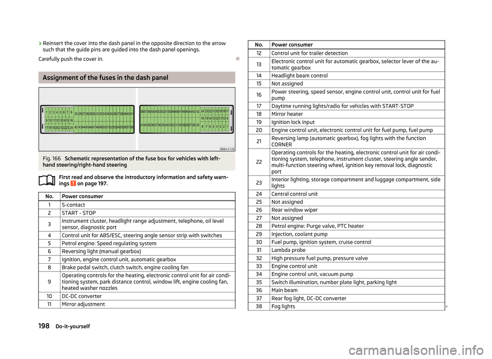
Assignment of the fuses in the dash panel
Fig. 166
Schematic representation of the fuse box for vehicles with left-
hand steering/right-hand steering
First read and observe the introductory information and safety warn-ings
on page 197.
No.Power consumer1S-contact2START - STOP3Instrument cluster, headlight range adjustment, telephone, oil level
sensor, diagnostic port4Control unit for ABS/ESC, steering angle sensor strip with switches5Petrol engine: Speed regulating system6Reversing light (manual gearbox)7Ignition, engine control unit, automatic gearbox8Brake pedal switch, clutch switch, engine cooling fan9Operating controls for the heating, electronic control unit for air condi-
tioning system, park distance control, window lift, engine cooling fan, heated washer nozzles10DC-DC converter11Mirror adjustmentNo.Power consumer12Control unit for trailer detection13Electronic control unit for automatic gearbox, selector lever of the au-tomatic gearbox14Headlight beam control15Not assigned16Power steering, speed sensor, engine control unit, control unit for fuel
pump17Daytime running lights/radio for vehicles with START-STOP18Mirror heater19Ignition lock input20Engine control unit, electronic control unit for fuel pump, fuel pump21Reversing lamp (automatic gearbox), fog lights with the function
CORNER
22
Operating controls for the heating, electronic control unit for air condi- tioning system, telephone, instrument cluster, steering angle sender,
multi-function steering wheel, ignition key removal lock, diagnostic
port23Interior lighting, storage compartment and luggage compartment, side
lights24Central control unit25Not assigned26Rear window wiper27Not assigned28Petrol engine: Purge valve, PTC heater29Injection, coolant pump30Fuel pump, ignition system, cruise control31Lambda probe32High pressure fuel pump, pressure valve33Engine control unit34Engine control unit, vacuum pump35Switch illumination, number plate light, parking light36Main beam37Rear fog light, DC-DC converter38Fog lights 198Do-it-yourself