ESP SKODA ROOMSTER 2010 1.G Owner's Manual
[x] Cancel search | Manufacturer: SKODA, Model Year: 2010, Model line: ROOMSTER, Model: SKODA ROOMSTER 2010 1.GPages: 231, PDF Size: 12.91 MB
Page 5 of 231
Contents
4
Driving Tips
. . . . . . . . . . . . . . . . . . . . . . . . . . . . . .
Intelligent Technology
. . . . . . . . . . . . . . . . . . . . . . . .
Electronic stability programme (ESP)* . . . . . . . . . .
Brakes . . . . . . . . . . . . . . . . . . . . . . . . . . . . . . . . . . . . . . .
Brake booster . . . . . . . . . . . . . . . . . . . . . . . . . . . . . . . .
Antilock brake system (ABS) . . . . . . . . . . . . . . . . . . .
Brake Assist* . . . . . . . . . . . . . . . . . . . . . . . . . . . . . . . . .
Uphill Start Assist* . . . . . . . . . . . . . . . . . . . . . . . . . . . .
Electrohydraulic power steering . . . . . . . . . . . . . . .
Tyre pressure monitoring system* . . . . . . . . . . . . . .
Diesel particle filter* (diesel engine) . . . . . . . . . . . .
Driving and the Environment
. . . . . . . . . . . . . . . . .
The first 1 500 kilometres and then afterwards . .
Catalytic converter . . . . . . . . . . . . . . . . . . . . . . . . . . . .
Driving in an economical and environmentally
conscious manner . . . . . . . . . . . . . . . . . . . . . . . . . . . .
Environmental compatibility . . . . . . . . . . . . . . . . . . .
Motoring abroad . . . . . . . . . . . . . . . . . . . . . . . . . . . . .
Avoiding damage to your vehicle . . . . . . . . . . . . . .
Driving through bodies of water on roads . . . . . . .
Towing a trailer
. . . . . . . . . . . . . . . . . . . . . . . . . . . . . . . .
Towing a trailer . . . . . . . . . . . . . . . . . . . . . . . . . . . . . . .
General Maintenance
. . . . . . . . . . . . . . .
Taking care of your ve hicle and cleaning the
vehicle
. . . . . . . . . . . . . . . . . . . . . . . . . . . . . . . . . . . . . . . . .
General . . . . . . . . . . . . . . . . . . . . . . . . . . . . . . . . . . . . . .
Care of the exterior of vehicle . . . . . . . . . . . . . . . . . .
Care of the interior of vehicle . . . . . . . . . . . . . . . . . .
Fuel
. . . . . . . . . . . . . . . . . . . . . . . . . . . . . . . . . . . . . . . . . . . .
Petrol . . . . . . . . . . . . . . . . . . . . . . . . . . . . . . . . . . . . . . . .
Diesel . . . . . . . . . . . . . . . . . . . . . . . . . . . . . . . . . . . . . . .
Refuelling . . . . . . . . . . . . . . . . . . . . . . . . . . . . . . . . . . . .
Inspecting and replenishing
. . . . . . . . . . . . . . . . . .
Engine compartment . . . . . . . . . . . . . . . . . . . . . . . . .
Engine oil . . . . . . . . . . . . . . . . . . . . . . . . . . . . . . . . . . . . Cooling system . . . . . . . . . . . . . . . . . . . . . . . . . . . . . . .
Brake fluid . . . . . . . . . . . . . . . . . . . . . . . . . . . . . . . . . . . .
Battery . . . . . . . . . . . . . . . . . . . . . . . . . . . . . . . . . . . . . . .
Windshield washer system . . . . . . . . . . . . . . . . . . . . .
Wheels and Tyres
. . . . . . . . . . . . . . . . . . . . . . . . . . . . . .
Wheels . . . . . . . . . . . . . . . . . . . . . . . . . . . . . . . . . . . . . . .
Accessories, changes and replacement of partsAccessories and replacement parts . . . . . . . . . . . . .
Technical changes . . . . . . . . . . . . . . . . . . . . . . . . . . . . .
Vehicles of category N1 . . . . . . . . . . . . . . . . . . . . . . . .Breakdown assistance
. . . . . . . . . . . . . .
Breakdown assistance
. . . . . . . . . . . . . . . . . . . . . . . . .
First-aid box* and Warning triangle* . . . . . . . . . . . .
Fire extinguisher* . . . . . . . . . . . . . . . . . . . . . . . . . . . . .
Vehicle tool kit . . . . . . . . . . . . . . . . . . . . . . . . . . . . . . . .
Tyre repair kit . . . . . . . . . . . . . . . . . . . . . . . . . . . . . . . . .
Spare wheel* . . . . . . . . . . . . . . . . . . . . . . . . . . . . . . . . .
Changing a wheel . . . . . . . . . . . . . . . . . . . . . . . . . . . . .
Jump-starting . . . . . . . . . . . . . . . . . . . . . . . . . . . . . . . . .
Tow-starting and towing vehicle . . . . . . . . . . . . . . . .
Fuses and light bulbs
. . . . . . . . . . . . . . . . . . . . . . . . . .
Electric fuses . . . . . . . . . . . . . . . . . . . . . . . . . . . . . . . . . .
Bulbs . . . . . . . . . . . . . . . . . . . . . . . . . . . . . . . . . . . . . . . . .
Praktik
. . . . . . . . . . . . . . . . . . . . . . . . . . . . . . . . . . . . . .
Praktik
. . . . . . . . . . . . . . . . . . . . . . . . . . . . . . . . . . . . . . . . .
Lashing eyes . . . . . . . . . . . . . . . . . . . . . . . . . . . . . . . . . .
Adjustable safety partition behind the front seats
Fixing of the loading floor . . . . . . . . . . . . . . . . . . . . . .
Adjustment of the safety partition . . . . . . . . . . . . . .
Emergency unlocking of the loading area door . .
Technical Data
. . . . . . . . . . . . . . . . . . . . . . . . . .
Technical Data
. . . . . . . . . . . . . . . . . . . . . . . . . . . . . . . .
General information . . . . . . . . . . . . . . . . . . . . . . . . . .
Used abbreviations . . . . . . . . . . . . . . . . . . . . . . . . . . .
Performances . . . . . . . . . . . . . . . . . . . . . . . . . . . . . . . .
Weight . . . . . . . . . . . . . . . . . . . . . . . . . . . . . . . . . . . . . . .
Identification details . . . . . . . . . . . . . . . . . . . . . . . . . .
Fuel consumption according to the ECE standards and
EU guidelines . . . . . . . . . . . . . . . . . . . . . . . . . . . . . . . .
Dimensions . . . . . . . . . . . . . . . . . . . . . . . . . . . . . . . . . .
Engine oil specifications . . . . . . . . . . . . . . . . . . . . . . .
1.2 ltr./51 kW - EU5 / EU2 DDK . . . . . . . . . . . . . . . . .
1.2 ltr./63 kW TSI - EU5 . . . . . . . . . . . . . . . . . . . . . . . .
1.2 ltr./77 kW TSI - EU5 . . . . . . . . . . . . . . . . . . . . . . . .
1.6 ltr./66 kW TDI CR DPF - EU5 . . . . . . . . . . . . . . . .
1.6 ltr./77 kW TDI CR DPF - EU5 . . . . . . . . . . . . . . . .
Index
. . . . . . . . . . . . . . . . . . . . . . . . . . . . . . . . . . . . . . . .
133133133135136136137137137138139141141142142145146146147148148151151151151155158158158159161161163
165167168172173173179179179179181181181181181182182183186188191191196203203203203203204204
205205205205205205205206207208210212214216218221
s16g.4.book Page 4 Wednesda y, February 10, 2010 3:53 PM
Page 7 of 231
Layout of this Owner's Manual (explanations)
6
Layout of this Owner's Manual (explanations)The Owner's Manual has been systematically designed, in order to make it easy for you
to find and absorb the information you require.Chapters, table of contents and subject indexThe text of the Owner's manual is divided into relatively short sections which are
combined into easy-to-read chapters. The chapter you are reading at any particular
moment is highlighted at the bottom right of the page.
The Table of contents is arranged according to the chapters and the detailed Subject
index at the end of the Owner's Manual helps you to rapidly find the information you
are looking for.SectionsThe majority of Sections apply to all models.
Since there is a wide range of different equipment and options available it is clearly
unavoidable, despite dividing the contents into sections, that mention may be made
of equipment whic h is not fitted to your vehicle.
Equipment which is marked * is only standard on certain vehicle model versions or
only suppliable as optional equipment for certain models.Brief information and instructionsEach section has a Heading.
This is followed by Brief information (in large italic lettering), which tells you the
subject which is dealt with in this section.
Most of the illustrations are accompanied by an Instruction (in relatively large letters)
which explains to you in a straightforw ard way the action you have to take. Work steps
which have to be carried out are illustrated with a hyphen.Direction indicationsAll direction indications such as “left”, “right”, “front”, “rear” relate to the direction of
travel of the vehicle.Explanation of symbols Equipment which is marked in such a way is only standard on certain vehicle model
versions or only suppliable as opti onal equipment for certain models.
End of a section. The section is continued on the next page.NotesAll four kinds of notes, which are used in th e text, are always stated at the end of the
respective section.
WARNING
The most important notes are marked with the heading Warning. These
Warning notes draw your attention to a serious risk of accident or injury. While
reading the text you will frequently en counter a double arrow followed by a
small warning symbol. This symbol is intended to draw your attention to a
Warning note at the end of the section to which you must pay careful attention.
Caution
A Caution note draws your attention to the possib ility of damage to your vehicle (e.g.
damage to gearbox), or points ou t general risks of an accident.
For the sake of the environment
An Environmental note draws your attention to environmental protection aspects.
This is where you will, for example, find tips aimed at reducing your fuel consumption.
Note
A normal Note draws your attention in a general way to important information.Direction indicationsAll direction indications such as “left”, “right”, “front”, “rear” relate to the direction of
travel of the vehicle.MeasuresIn some countries British measures can be given.
s16g.4.book Page 6 Wednesda y, February 10, 2010 3:53 PM
Page 10 of 231
Cockpit9
Using the system
Safety
Driving Tips
General Maintenance
Breakdown assistance
Praktik
Technical Data
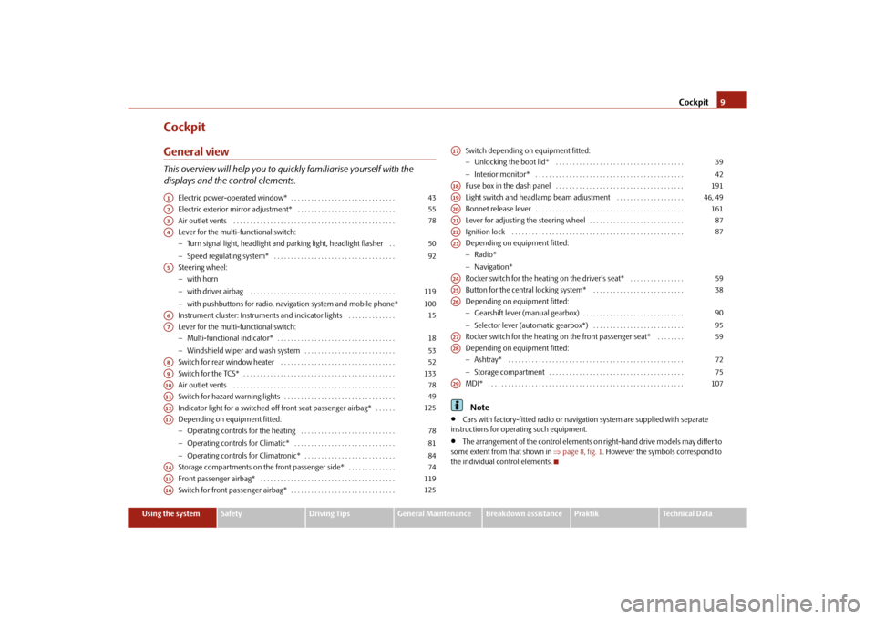
CockpitGeneral viewThis overview will help you to quickly familiarise yourself with the
displays and the control elements.
Electric power-operated window* . . . . . . . . . . . . . . . . . . . . . . . . . . . . . . .
Electric exterior mirror adjustment* . . . . . . . . . . . . . . . . . . . . . . . . . . . . .
Air outlet vents . . . . . . . . . . . . . . . . . . . . . . . . . . . . . . . . . . . . . . . . . . . . . . . .
Lever for the multi-functional switch:
Turn signal light, headlight and parking light, headlight flasher . .
Speed regulating system* . . . . . . . . . . . . . . . . . . . . . . . . . . . . . . . . . . . .
Steering wheel:
with horn
with driver airbag . . . . . . . . . . . . . . . . . . . . . . . . . . . . . . . . . . . . . . . . . . .
with pushbuttons for radio, navi gation system and mobile phone*
Instrument cluster: Instruments and indicator lights . . . . . . . . . . . . . .
Lever for the multi-functional switch:
Multi-functional indicator* . . . . . . . . . . . . . . . . . . . . . . . . . . . . . . . . . . .
Windshield wiper and wash system . . . . . . . . . . . . . . . . . . . . . . . . . . .
Switch for rear window heater . . . . . . . . . . . . . . . . . . . . . . . . . . . . . . . . . .
Switch for the TCS* . . . . . . . . . . . . . . . . . . . . . . . . . . . . . . . . . . . . . . . . . . . . .
Air outlet vents . . . . . . . . . . . . . . . . . . . . . . . . . . . . . . . . . . . . . . . . . . . . . . . .
Switch for hazard warning lights . . . . . . . . . . . . . . . . . . . . . . . . . . . . . . . . .
Indicator light for a switched off front seat passenger airbag* . . . . . .
Depending on equipment fitted:
Operating controls for the heating . . . . . . . . . . . . . . . . . . . . . . . . . . . .
Operating controls for Climatic* . . . . . . . . . . . . . . . . . . . . . . . . . . . . . .
Operating controls for Climatronic* . . . . . . . . . . . . . . . . . . . . . . . . . . .
Storage compartments on the front passenger side* . . . . . . . . . . . . . .
Front passenger airbag* . . . . . . . . . . . . . . . . . . . . . . . . . . . . . . . . . . . . . . . .
Switch for front passenger airbag* . . . . . . . . . . . . . . . . . . . . . . . . . . . . . . . Switch depending on equipment fitted:
Unlocking the boot lid* . . . . . . . . . . . . . . . . . . . . . . . . . . . . . . . . . . . . . .
Interior monitor* . . . . . . . . . . . . . . . . . . . . . . . . . . . . . . . . . . . . . . . . . . . .
Fuse box in the dash panel . . . . . . . . . . . . . . . . . . . . . . . . . . . . . . . . . . . . . .
Light switch and headlamp beam adjustment . . . . . . . . . . . . . . . . . . . .
Bonnet release lever . . . . . . . . . . . . . . . . . . . . . . . . . . . . . . . . . . . . . . . . . . . .
Lever for adjusting the steering wheel . . . . . . . . . . . . . . . . . . . . . . . . . . . .
Ignition lock . . . . . . . . . . . . . . . . . . . . . . . . . . . . . . . . . . . . . . . . . . . . . . . . . . .
Depending on equipment fitted:
Radio*
Navigation*
Rocker switch for the heating on the driver's seat* . . . . . . . . . . . . . . . .
Button for the central locking system* . . . . . . . . . . . . . . . . . . . . . . . . . . .
Depending on equipment fitted:
Gearshift lever (manual gearbox) . . . . . . . . . . . . . . . . . . . . . . . . . . . . . .
Selector lever (automatic gearbox*) . . . . . . . . . . . . . . . . . . . . . . . . . . .
Rocker switch for the heating on the front passenger seat* . . . . . . . .
Depending on equipment fitted:
Ashtray* . . . . . . . . . . . . . . . . . . . . . . . . . . . . . . . . . . . . . . . . . . . . . . . . . . . .
Storage compartment . . . . . . . . . . . . . . . . . . . . . . . . . . . . . . . . . . . . . . . .
MDI* . . . . . . . . . . . . . . . . . . . . . . . . . . . . . . . . . . . . . . . . . . . . . . . . . . . . . . . . . .
Note
Cars with factory-fitted radio or naviga tion system are supplied with separate
instructions for operating such equipment.
The arrangement of the control elements on right-hand drive models may differ to
some extent from that shown in page 8, fig. 1. However the symbols correspond to
the individual control elements.
A1
43
A2
55
A3
78
A4
5092
A5
119100
A6
15
A7
1853
A8
52
A9
133
A10
78
A11
49
A12
125
A13
788184
A14
74
A15
119
A16
125
A17
3942
A18
191
A19
46, 49
A20
161
A21
87
A22
87
A23A24
59
A25
38
A26
9095
A27
59
A28
7275
A29
107
s16g.4.book Page 9 Wednesda y, February 10, 2010 3:53 PM
Page 24 of 231
Instruments and warning lights23
Using the system
Safety
Driving Tips
General Maintenance
Breakdown assistance
Praktik
Technical Data
Note
If warning messages are shown in the information display page 23, these
messages can be confirmed with the button on the windshield wiper lever in order
to call up the main menu.
If you do not activate the information display at that moment, the menu shifts to
one level higher every 10 seconds.
The operation of the factory-fitted radio* or the navigation system* is described in
separate operating instructions to be found in the on-board literature.
Door, luggage compartment door and bonnet ajar warningThe door, luggage compartment and bonnet ajar warning lights up if at least one door,
the luggage compartment or bonnet are not closed. The symbol indicates which door
is still open or whether the luggage compartment door or bonnet is not closed.
The symbol goes out as soon as the doors, luggage compartment door and bonnet are
completely closed.
A warning signal sounds if the car is driven at a speed of more than 6km/hour and if
the engine or the luggage compartment door is open.Auto Check ControlCar stateThe Auto Check Control carries out a chec k of certain functions and vehicle compo-
nents. The check is performed constantly when the ignition is switched on, both when
the vehicle is stationary, as well as when driving.
Some operational faults, urgent repairs, service work or other information appear in
the display of the instrument cluster. The di splays are shown with a red or yellow light
symbol depending on the priority of the message.
The red symbols indicate danger (priority 1) while the yellow symbols indicate a
warning (priortity 2). Information for the driver may also appear in addition to the
symbols page 25. Shown in the menu
Vehicle status, if there is at least one error message. After selecting
this menu the first of the error messages is displayed. Several error messages are
shown on the display under the message e.g. 1/3 . This indicates that the first of a total
of three error messages is displayed. The respective messages are displayed one after
the other in an interval of 5 seconds. Check as soon as possible the displayed error
messages.
As long as the operational faults are not rectified, the symbols are always indicated
again. After the first display, the symbol s are indicated without information for the
driver.
If a fault occurs, a warning signal will also so und in addition to the symbol and text in
the display:
Priority 1 - three warning signals
Priority 2 - one warning signal
Red symbols
A red symbol signals danger.– Bring the vehicle to a stop.
– Switch the engine off.
– Investigate the function indicated.
– Obtain professional assistance.
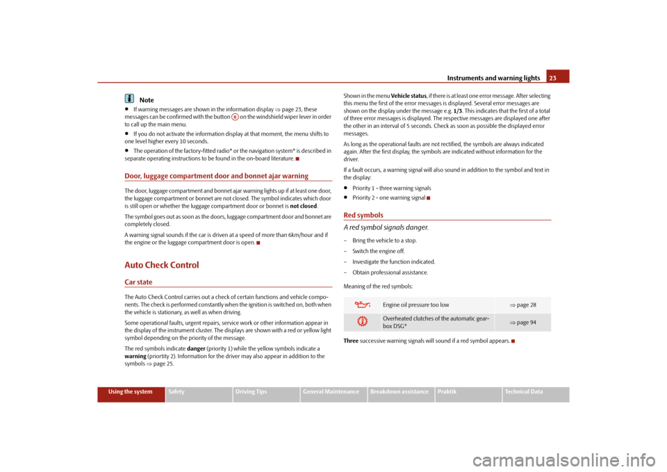
Meaning of the red symbols:
Three successive warning signals will sound if a red symbol appears.
AB
Engine oil pressure too low
page 28
Overheated clutches of the automatic gear-
box DSG*
page 94
s16g.4.book Page 23 Wednesda y, February 10, 2010 3:53 PM
Page 25 of 231
Instruments and warning lights
24
Yellow symbols
A yellow symbol signals a warning.Check the relevant function as soon as possible.
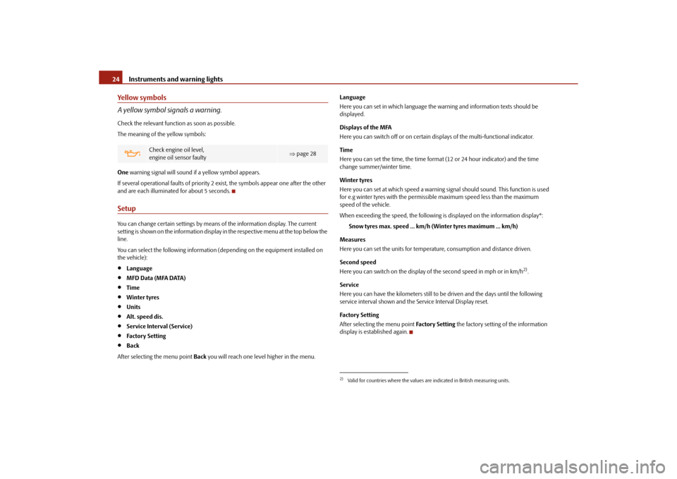
The meaning of the yellow symbols:
One warning signal will sound if a yellow symbol appears.
If several operational faults of priority 2 exist, the symbols appear one after the other
and are each illuminate d for about 5 seconds.SetupYou can change certain setti ngs by means of the information display. The current
setting is shown on the information display in the respective menu at the top below the
line.
You can select the following information (d epending on the equipment installed on
the vehicle):
Language
MFD Data (MFA DATA)
Time
Winter tyres
Units
Alt. speed dis.
Service Interval (Service)
Factory Setting
Back
After selecting the menu point Back you will reach one level higher in the menu. Language
Here you can set in which language the
warning and information texts should be
displayed.
Displays of the MFA
Here you can switch off or on certain displays of the multi-functional indicator.
Time
Here you can set the time, the time format (12 or 24 hour indicator) and the time
change summer/winter time.
Winter tyres
Here you can set at which speed a warning signal should sound. This function is used
for e.g winter tyres with the permissible maximum speed less than the maximum
speed of the vehicle.
When exceeding the speed, the following is displayed on the information display*:
Snow tyres max. speed ... km/h (Winter tyres maximum ... km/h)
Measures
Here you can set the units for temperat ure, consumption and distance driven.
Second speed
Here you can switch on the display of the second speed in mph or in km/h
2).
Service
Here you can have the kilometers still to be driven and the days until the following
service interval shown and the Service Interval Display reset.
Factory Setting
After selecting the menu point Factory Setting the factory setting of the information
display is established again.
Check engine oil level,
engine oil sensor faulty
page 28
2)Valid for countries where the values ar e indicated in British measuring units.
s16g.4.book Page 24 Wednesday, February 10, 2010 3:53 PM
Page 27 of 231
Instruments and warning lights
26
WARNING
If you do not pay attention to the warning lights coming on and the corre-
sponding descriptions and warning notes, this may result in severe body inju-
ries or major vehicle damage.
The engine compartment of your car is a hazardous area. There is a risk of
injuries, scalding, accidents and fire wh en working in the engine compartment,
e.g. inspecting and replenishing oil and other fluids. It is also essential to
observe all warnings page 162, “Working in the engine compartment”.Note
Arrangement of the indicator lights depends on the model and model version.
Operational faults are shown in the instrument cluster as red symbols (priority 1 -
danger) or yellow symbol s (priority 2 - warning).
Turn signal system
Either the left
or right
indicator light flashes depending on the position of the turn
signal lever.
The indicator light flashes at twice its normal rate if a turn signal light fails.
Switching off the hazard warning light system is switched on will cause all of the turn
signal lights as well as both indicator lights to flash.
Further information about the turn signal system page 50.
Main beam
The indicator light
comes on when the main beam is selected or also when the
headlight flasher is operated.
Further information about the main beam page 50.
Low beam
The warning light
comes on when low beam is selected page 46.
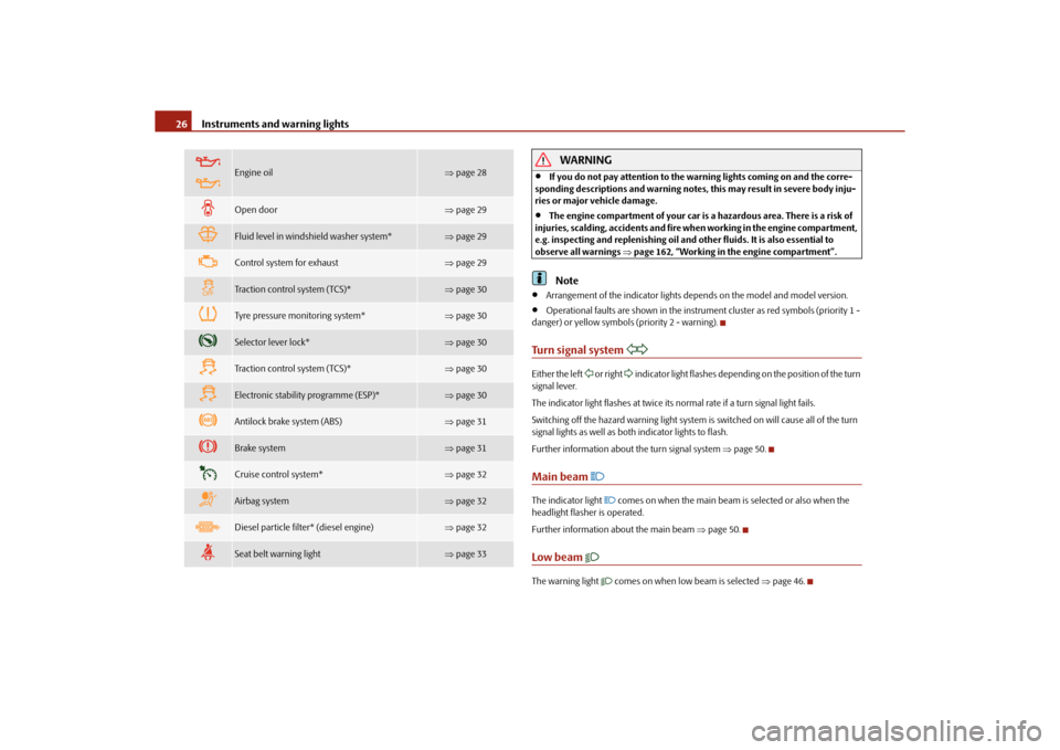
Engine oil
page 28
Open door
page 29
Fluid level in windshield washer system*
page 29
Control system for exhaust
page 29
Traction control system (TCS)*
page 30
Tyre pressure monitoring system*
page 30
Selector lever lock*
page 30
Traction control system (TCS)*
page 30
Electronic stability programme (ESP)*
page 30
Antilock brake system (ABS)
page 31
Brake system
page 31
Cruise control system*
page 32
Airbag system
page 32
Diesel particle filter* (diesel engine)
page 32
Seat belt warning light
page 33
s16g.4.book Page 26 Wednesda y, February 10, 2010 3:53 PM
Page 31 of 231
Instruments and warning lights
30
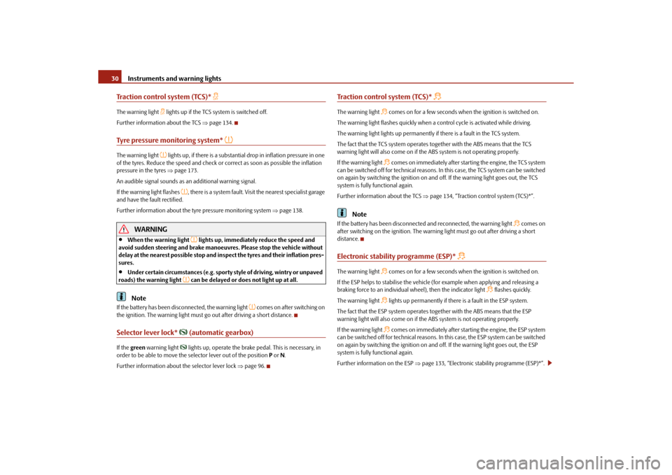
Traction control system (TCS)*
The warning light
lights up if the TCS system is switched off.
Further information about the TCS page 134.
Tyre pressure monitoring system*
The warning light
lights up, if there is a substantia l drop in inflation pressure in one
of the tyres. Reduce the speed and check or correct as soon as possible the inflation
pressure in the tyres page 173.
An audible signal sounds as an additional warning signal.
If the warning light flashes
, there is a system fault. Visit the nearest specialist garage
and have the fault rectified.
Further information about the tyre pressure monitoring system page 138.
WARNING
When the warning light
lights up, immediately reduce the speed and
avoid sudden steering and brake manoeuvres. Please stop the vehicle without
delay at the nearest possible stop and in spect the tyres and their inflation pres-
sures.
Under certain circumstances (e.g. sporty style of driving, wintry or unpaved
roads) the warning light
can be delayed or does not light up at all.
Note
If the battery has been disc onnected, the warning light
comes on after switching on
the ignition. The warning light must go out after driving a short distance.
Selector lever lock*
(automatic gearbox)
If the green warning light
lights up, operate the brake pedal. This is necessary, in
order to be able to move the selector lever out of the position P or N.
Further information about the selector lever lock page 96.
Traction control system (TCS)*
The warning light
comes on for a few seconds when the ignition is switched on.
The warning light flashes quickly when a control cycle is activated while driving.
The warning light lights up permanently if there is a fault in the TCS system.
The fact that the TCS system operates together with the ABS means that the TCS
warning light will also come on if the ABS system is not operating properly.
If the warning light comes on immediately after starting the engine, the TCS system
can be switched off for technical reasons. In this case, the TCS system can be switched
on again by switching the igni tion on and off. If the warning light goes out, the TCS
system is fully functional again.
Further information about the TCS page 134, “Traction control system (TCS)*”.
Note
If the battery has been disconnected and reconnected, the warning light
comes on
after switching on the ignition. The warning light must go out after driving a short
distance.
Electronic stability programme (ESP)*
The warning light
comes on for a few seconds when the ignition is switched on.
If the ESP helps to stabilise the vehicle (f or example when applying and releasing a
braking force to an individual wheel), then the indicator light
flashes quickly.
The warning light
lights up permanently if there is a fault in the ESP system.
The fact that the ESP system operates together with the ABS means that the ESP
warning light will also come on if the ABS system is not operating properly.
If the warning light comes on immediately after starting the engine, the ESP system
can be switched off for technical reasons. In this case, the ESP system can be switched
on again by switching the igni tion on and off. If the warning light goes out, the ESP
system is fully functional again.
Further information on the ESP page 133, “Electronic stab ility programme (ESP)*”.
s16g.4.book Page 30 Wednesda y, February 10, 2010 3:53 PM
Page 44 of 231
Unlocking and locking43
Using the system
Safety
Driving Tips
General Maintenance
Breakdown assistance
Praktik
Technical Data
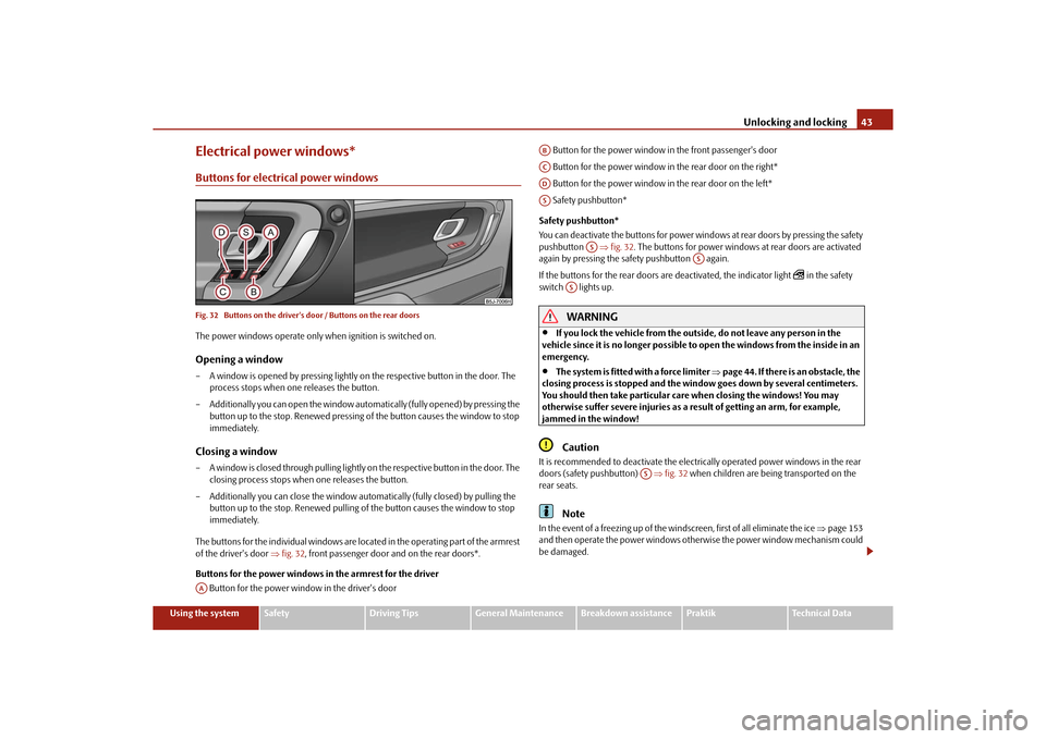
Electrical power windows*Buttons for electrical power windowsFig. 32 Buttons on the driver's door / Buttons on the rear doorsThe power windows operate only when ignition is switched on.Opening a window– A window is opened by pressing lightly on the respective button in the door. The
process stops when one releases the button.
– Additionally you can open the window automatically (fully opened) by pressing the button up to the stop. Renewe d pressing of the button causes the window to stop
immediately.Closing a window– A window is closed through pulling lightly on the respective button in the door. The
closing process stops when one releases the button.
– Additionally you can close the window auto matically (fully closed) by pulling the
button up to the stop. Renewed pulling of the button causes the window to stop
immediately.
The buttons for the individual windows are located in the operating part of the armrest
of the driver's door fig. 32 , front passenger door and on the rear doors*.
Buttons for the power windows in the armrest for the driver Button for the power window in the driver's door Button for the power window in the front passenger's door
Button for the power window in the rear door on the right*
Button for the power window in the rear door on the left*
Safety pushbutton*
Safety pushbutton*
You can deactivate the buttons for power wind ows at rear doors by pressing the safety
pushbutton fig. 32 . The buttons for power windows at rear doors are activated
again by pressing the safety pushbutton again.
If the buttons for the rear doors are deactivated, the indicator light
in the safety
switch lights up.
WARNING
If you lock the vehicle from the outside, do not leave any person in the
vehicle since it is no longer possible to open the windows from the inside in an
emergency.
The system is fitted with a force limiter page 44. If there is an obstacle, the
closing process is stopped and the window goes down by several centimeters.
You should then take particular care when closing the windows! You may
otherwise suffer severe injuries as a re sult of getting an arm, for example,
jammed in the window!Caution
It is recommended to deactivate the electrically operated power windows in the rear
doors (safety pushbutton) fig. 32 when children are being transported on the
rear seats.
Note
In the event of a freezing up of the windscreen, first of all eliminate the ice page 153
and then operate the power windows otherwise the power window mechanism could
be damaged.
AA
ABACADAS
AS
AS
AS
AS
s16g.4.book Page 43 Wednesda y, February 10, 2010 3:53 PM
Page 50 of 231
Lights and Visibility49
Using the system
Safety
Driving Tips
General Maintenance
Breakdown assistance
Praktik
Technical Data
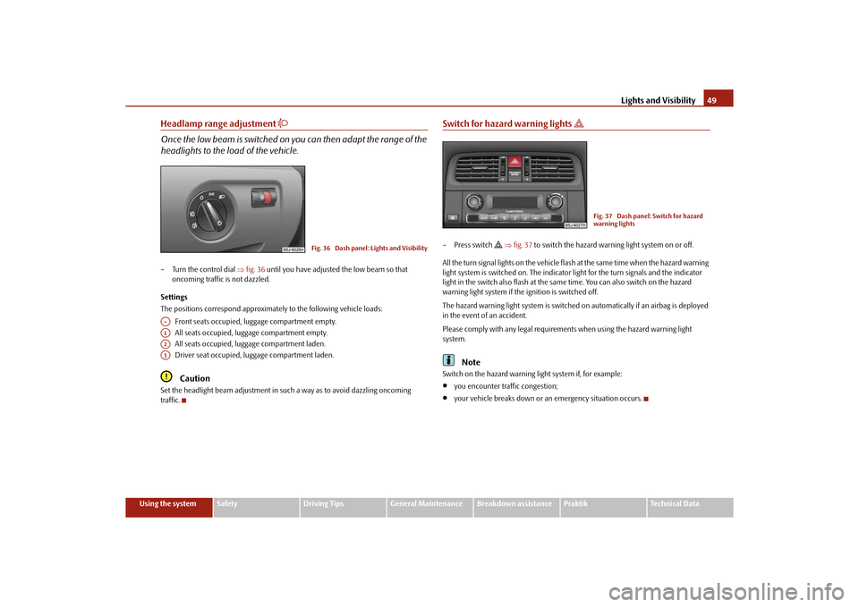
Headlamp range adjustment
Once the low beam is switched on you can then adapt the range of the
headlights to the lo ad of the vehicle.– Turn the control dial fig. 36 until you have adjusted the low beam so that
oncoming traffic is not dazzled.
Settings
The positions correspond approximately to the following vehicle loads:
Front seats occupied, luggage compartment empty.
All seats occupied, luggage compartment empty.
All seats occupied, luggage compartment laden.
Driver seat occupied, lu ggage compartment laden.
Caution
Set the headlight beam adjustment in su ch a way as to avoid dazzling oncoming
traffic.
Switch for hazard warning lights
– Press switch
fig. 37 to switch the hazard warning light system on or off.
All the turn signal lights on the vehicle flas h at the same time when the hazard warning
light system is switched on. The indicator light for the turn signals and the indicator
light in the switch also flash at the same time. You can also switch on the hazard
warning light system if the ignition is switched off.
The hazard warning light system is switched on automatically if an airbag is deployed
in the event of an accident.
Please comply with any legal requirements when using the hazard warning light
system.
Note
Switch on the hazard warning light system if, for example:
you encounter traffic congestion;
your vehicle breaks down or an emergency situation occurs.
Fig. 36 Dash panel: Lights and Visibility
A-A1A2A3
Fig. 37 Dash panel: Switch for hazard
warning lights
s16g.4.book Page 49 Wednesda y, February 10, 2010 3:53 PM
Page 61 of 231
Seats and Storage
60
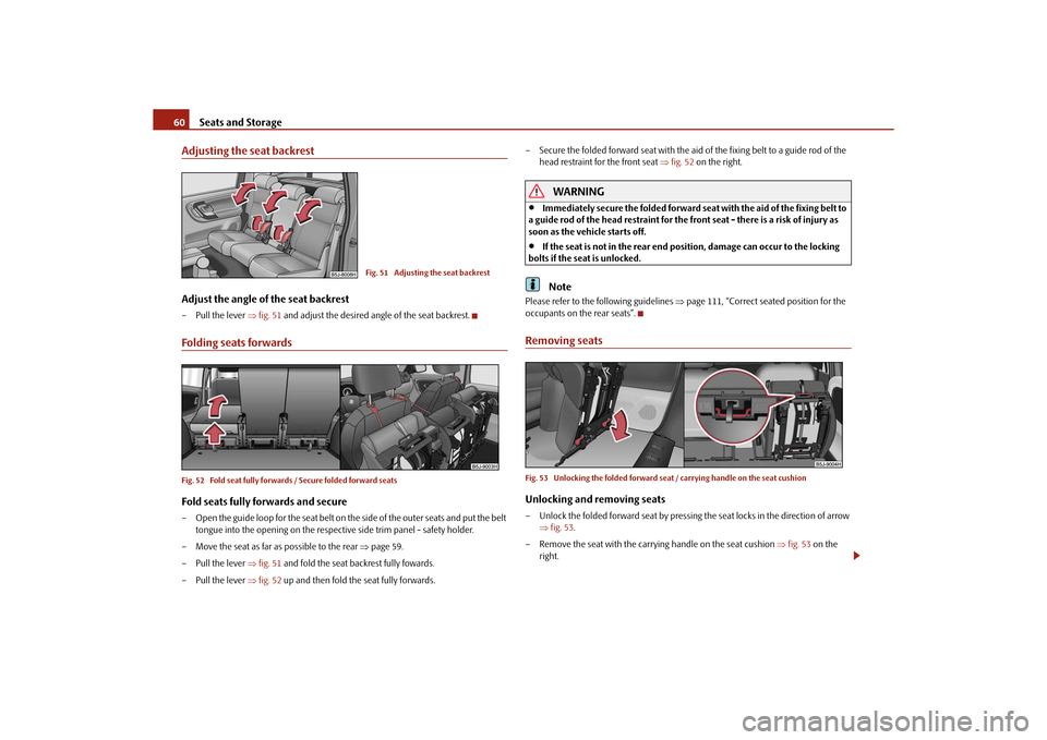
Adjusting the seat backrestAdjust the angle of the seat backrest– Pull the lever fig. 51 and adjust the desired angle of the seat backrest.Folding seats forwardsFig. 52 Fold seat fully forwards / Secure folded forward seatsFold seats fully forwards and secure– Open the guide loop for the seat belt on th e side of the outer seats and put the belt
tongue into the opening on the respective side trim panel - safety holder.
– Move the seat as far as possible to the rear page 59.
– Pull the lever fig. 51 and fold the seat backrest fully fowards.
– Pull the lever fig. 52 up and then fold the seat fully forwards. – Secure the folded forward seat with the aid of the fixing belt to a guide rod of the
head restraint for the front seat fig. 52 on the right.
WARNING
Immediately secure the folded forward seat with the aid of the fixing belt to
a guide rod of the head restraint for the front seat - there is a risk of injury as
soon as the vehicle starts off.
If the seat is not in the rear end po sition, damage can occur to the locking
bolts if the seat is unlocked.Note
Please refer to the following guidelines page 111, “Correct seated position for the
occupants on the rear seats”.Removing seatsFig. 53 Unlocking the folded forward seat / carrying handle on the seat cushionUnlocking and removing seats– Unlock the folded forward seat by pressing the seat locks in the direction of arrow fig. 53 .
– Remove the seat with the carrying handle on the seat cushion fig. 53 on the
right.
Fig. 51 Adjusting the seat backrest
s16g.4.book Page 60 Wednesda y, February 10, 2010 3:53 PM