ESP SKODA ROOMSTER 2010 1.G Owner's Guide
[x] Cancel search | Manufacturer: SKODA, Model Year: 2010, Model line: ROOMSTER, Model: SKODA ROOMSTER 2010 1.GPages: 231, PDF Size: 12.91 MB
Page 138 of 231
Intelligent Technology137
Using the system
Safety
Driving Tips
General Maintenance
Breakdown assistance
Praktik
Technical Data
WARNING
The ABS can also not overcome the physical limits of your vehicle. Please do
not forget this, particularly when driving on icy or wet road surfaces. If the ABS
is operating within the control range, adapt your speed immediately to the
conditions of the road surface and the traffic situation. The increased safety
offered by the ABS must not tempt you to take greater risks than otherwise -
risk of an accident!
The normal braking system is still fully functional if there is an ABS fault.
Visit a specialist garage as quickly as poss ible and adjust your style of driving to
take account of the ABS fault in the meantime since you will not know the extent
of the fault and in how far the braking efficiency is affected.Note
A warning light comes on if a fault occurs in the ABS system
page 31.
Changes to vehicle (e.g. on engine, on th e brakes, on chassis or another combina-
tion of tyres and wheels) can in fluence the function of the ABS page 179, “Accesso-
ries, changes and replacement of parts”.
Brake Assist*During a severe brake application (e.g. if a hazard exists), the Brake Assist increases the
braking force and thus makes it possible to rapidly produce the pressure required in
the brake system.
The majority of drivers do apply the brakes in good time in dangerous situations, but
do not depress the brake pedal with sufficient pressure. Consequently, it is not possible
for the vehicle to achieve its maximum deceleration and the vehicle covers a greater
distance than necessary.
The Brake Assist is activated by the very quick operation of the brake pedal. In such
cases, a much greater braking pressure exists than during a normal brake application.
This makes it possible, even with a relative ly low resistance of the brake pedal, to
produce an adequate pressure in the brake system in the shortest possible time, which
is required for maximum deceleration of th e vehicle. You must apply the brake pedal
firmly and hold it in this position in order to achieve the shortest possible braking
distance. The Brake Assist is able to help you achi
eve a shorter braking distance in emergency
situations by rapidly producing the pressure required in the brake system. It fully
exploits the attributes of the ABS. After you release the brake pedal, the function of the
Brake Assist is automatically switched off and the brakes operate in the normal way.
The Brake Assist is part of the ESP system. If a fault occurs in the ESP, the Brake Assist
function is also not available. Further information on the ESP page 133.
WARNING
The Brake Assist is also not able to overcome the physical limits of your
vehicle in terms of the braking distance required.
Adapt your speed to the conditions of the road surface and to the traffic situ-
ation.
The increased safety offered by the Brake Assist must not tempt you to take
a greater safety risk than otherwise.
Uphill Start Assist*The uphill start assist makes it easier to start off on steep hills. The system assists a start
off by holding the brake pressure produced by the brake pedal actuation for approx. 2
seconds after releasing the brake pedal. The driver can therefore move his foot from
the brake pedal to the accelerator pedal and start off on the slope, without having to
actuate the handbrake. The brake pressure drops gradually the more you operate the
accelerator pedal. If the vehicle does not start off within 2 seconds, it starts to roll back.
The uphill start assist is active as of a 3% slope, if the driver door is closed. It is always
active on slopes when in forward or reverse start off. When driving downhill, it is
inactive.Electrohydraulic power steeringThe power steering enables you to steer the vehicle with less physical force.
The steering characteristics can be changed by a specialist garage.
s16g.4.book Page 137 Wednesda y, February 10, 2010 3:53 PM
Page 140 of 231
Intelligent Technology139
Using the system
Safety
Driving Tips
General Maintenance
Breakdown assistance
Praktik
Technical Data
If the warning light
does not go out after the basic setting, there is a fault in the
system. Have the vehicle inspected by your nearest specialist garage.
Functional description
After the basic setting of the system the “adaptation” of the tyre inflation pressures and
then the tyre pressure control in the individual tyres are performed.
Warning light
lights up
If the tyre inflation pressure of at least one wheel is insufficiently inflated in comparison
to the stored basic value, the warning light
lights up. Inflate all tyres to the
specified inflation pressure page 173, “Tyre life” and then perform a basic setting of
the system.
Warning light
flashes
If the warning light flashes, there is a system fault. Have the vehicle inspected by your
nearest specialist garage.
WARNING
When the warning light
lights up, immediately reduce the speed and
avoid sudden steering and brake manoeuvr es. Please stop the vehicle without
delay at the nearest possible stop and in spect the tyres and their inflation pres-
sures.
The driver is responsible for the correct tyre inflation pressures. For this
reason, the tyre inflation pressu res must be checked regularly.
Under certain circumstances (e.g. sporty style of driving, wintry or unpaved
roads) the warning light
can be delayed or does not light up at all.
The tyre pressure monitoring system does not take away the responsibility
from the driver for the correct tyre inflation pressure.Note
The tyre pressure monitoring system:
does not replace the regular tyre inflatio n pressure control, because the system
cannot detect an even pressure loss;
cannot warn in case of very rapid tyre inflation pressure loss, e.g. in case of sudden
tyre damage. In this case ca refully bring the vehicle to a standstill without sudden
steering movements and without sharp braking.
Diesel particle filter* (diesel engine)In the diesel particle filter the resu lting soot particles are collected and
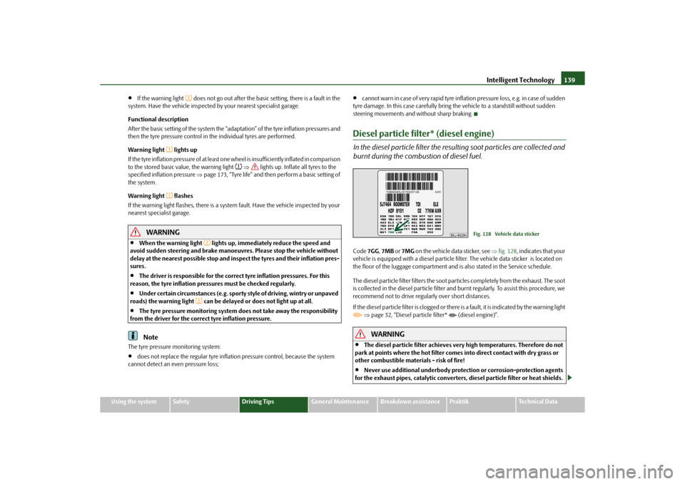
burnt during the combustion of diesel fuel.Code 7GG, 7MB or 7MG on the vehicle data sticker, see fig. 128 , indicates that your
vehicle is equipped with a diesel particle fi lter. The vehicle data sticker is located on
the floor of the luggage compartment and is also stated in the Service schedule.
The diesel particle filter filters the soot particles completely from the exhaust. The soot
is collected in the diesel particle filter and burnt regularly. To assist this procedure, we
recommend not to drive regu larly over short distances.
If the diesel particle filter is clogged or there is a fault, it is indicated by the warning light
page 32, “Diesel particle filter* (diesel engine)”.
WARNING
The diesel particle filter achieves very high temp eratures. Therefore do not
park at points where the hot filter comes into direct contact with dry grass or
other combustible materials - risk of fire!
Never use additional underbody protection or corrosion-protection agents
for the exhaust pipes, catalytic converters, diesel particle filter or heat shields.
Fig. 128 Vehicle data sticker
s16g.4.book Page 139 Wednesday, February 10, 2010 3:53 PM
Page 155 of 231
Taking care of your vehicle and cleaning the vehicle
154
Do not affix any stickers over the inside of the rear window to avoid damage to the
heating elements of the rear window heater .
We recommend using a preserva tive from Škoda genuine accessories offered by your
Škoda dealer.
Caution
Never remove snow or ice from the glass pa rts with warm or hot water - risk of
formation of cracks in the glass!
When removing snow or ice from the windows and mirror lenses make sure not to
damage the paintwork of the vehicle.
The headlight lensesPlease do not use any aggressi ve cleaning or chemical solvent products for cleaning
the front headlights - risk of damage to the plastic lenses. Please use soap and clean
warm water.
Caution
Never wipe the headlights dry and do not use any sharp objects for cleaning the plastic
lenses, this may result in damage to the protective paintwork and consequently in
formation of cracks on the headlight lenses, e.g through effect of chemical products.Door and window sealsThe rubber seals on the doors, boot lid, bonnet and windows remain supple and last
longer if you treat them from time to time with a rubber care product (e.g. with a spray
with silicone-free oil). You also avoid premature wear of the seals and prevent leakages
in this way. It is also easier to open the doors. Rubber seals which are well cared for also
do not stick together in cold winter weather.Locking cylinderWe recommend that you use the spray from Škoda original accessories with regreasing
and anticorrosive effect for de-icing locking cylinders.
Note
When washing your vehicle, ensure that as little water as possible gets into the locking
cylinders.WheelsSteel wheels
You should also thoroughly wash the wheels and wheel trims when giving your vehicle
its regular wash. This prevents any brake dust, dirt and road salt from sticking to the
wheel hubs. You can remove stubborn brake abrasion adhering to the wheels with an
industrial cleaner. Touch up any damage to the paintwork on the wheels before rust is
able to form.
Light alloy wheels
Regular care of light alloy wh eels is necessary in order to retain their decorative
appearance over long periods. It is particul arly important to remove any road salt and
brake abrasion from light alloy wheels every two weeks, otherwise the surface will
suffer. Wash thoroughly and then treat the wheels with a protective product for light
alloy wheels which does not contain any acidic componen ts. You should provide the
wheel hubs with a hard wax layer every thre e months. You must not use any products
which cause abrasion when treating the wheel hubs. Any damage to the paint layer on
the wheel hubs must be touched up immediately.
We recommend using a preservative from Šk oda genuine accessories offered by your
Škoda dealer.
WARNING
One should remember when cleaning th e wheels that moisture, ice and road
salt may adversely affect braking ef ficiency - risk of an accident!
Note
Severe layers of dirt on the wheels can also result in wheel imbalance. This may show
itself in the form of a wheel vibration which is transmitted to the steering wheel which,
in certain circumstances, can cause premature wear of the steering. This means it is
necessary to remove the dirt.
s16g.4.book Page 154 Wednesda y, February 10, 2010 3:53 PM
Page 160 of 231
Fuel159
Using the system
Safety
Driving Tips
General Maintenance
Breakdown assistance
Praktik
Technical Data
You can find information on refuelling
page 159, “Refuelling”.
Caution
Therefore, your vehicle can only be operated with diesel fuel which complies with
the standard EN 590 (standard DIN 51628 in Germany, standard ÖNORM C 1590 in
Austria). Filling the tank even only once wi th diesel fuel which does not comply with
the standard, can result in damage to the engine parts, the lubrication system, the fuel
and exhaust system.
If by mistake you have refuelled with a different fuel other than the diesel fuel
which complies to the above mentioned stan dards (e.g. petrol), on no account start
the engine! This can result in severe engine damage! Contact a specialist garage.
Water which has collected in the fuel fi lter can result in engine problems.
Your vehicle is not adapted for use of biofue l (RME), therefore this fuel must not be
refuelled and driven. The use of biofuel (RME) can lead to damage to the engine or the
fuel system.
Operation in winterWinter-grade diesel fuel
A different grade of diesel fuel is available at filling stations in winter than during the
summer. Using “summer-grade diesel fuel” at temperatures below 0°C can result in
operational problems because th e diesel becomes viscous as a result of paraffin sepa-
ration.
It is therefore the case that the standard EN 590 (standard DIN 51628 in Germany,
standard ÖNORM C 1590 in Austria) is the diesel fuel class prescribed for certain
periods of the year which can also be purc hased at the corresponding time during the
year. “Winter-grade diesel fuel” will still operate properly even at a temperature of -
20°C.
It is often the case in countries with different climatic conditions that diesel fuels avail-
able have a different temperature characteristic. The authorised Škoda Service Part-
ners and filling stations in the country concer ned will be able to provide you with infor-
mation regarding the diesel fuels available. Prewarming fuel
The vehicle is fitted with a fu
el filter prewarming system. This secures operation of a
vehicle using diesel fuel down to an environmental temperature of -25°C.
Caution
It is not permitted to add the various fuel additives on the market, including petrol, to
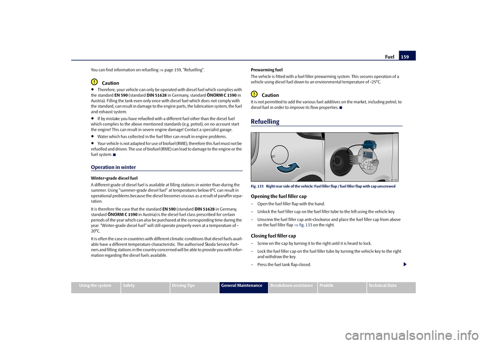
diesel fuel in order to improve its flow properties.RefuellingFig. 133 Right rear side of the vehicle: Fuel filler flap / fuel filler flap with cap unscrewedOpening the fuel filler cap– Open the fuel filler flap with the hand.
– Unlock the fuel filler cap on the fuel filler tube to the left using the vehicle key.
– Unscrew the fuel filler ca p anti-clockwise and place the fuel filler cap from above
on the fuel filler flap fig. 133 on the right.Closing fuel filler cap– Screw on the cap by turning it to the right until it is heard to lock.
– Lock the fuel filler cap on the fuel filler tube by turning the vehicle key to the right
and withdraw the key.
– Press the fuel tank flap closed.
s16g.4.book Page 159 Wednesda y, February 10, 2010 3:53 PM
Page 178 of 231
Wheels and Tyres177
Using the system
Safety
Driving Tips
General Maintenance
Breakdown assistance
Praktik
Technical Data
Winter tyresThe handling of your vehicle will be signif icantly improved when driving on wintry
roads if you fit winter tyres. Summer tyres do not offer the same grip on ice, snow and
at temperatures below 7 °C because of thei r construction (width, rubber blend, tread
pattern). This applies in particular to vehicles which are equipped with low-profile
tyres or high-speed tyres (code index H, V or W on wall of tyre).
Winter tyres must be mounted on all four wheels to obtain the best handling charac-
teristics.
You must only fit those types of winter tyre which are approved for your vehicle. The
permissible sizes of winter tyres are stated in your vehicle documents. Approvals may
differ because of na tional legislation.
Please remember that the tyres should be inflated to 20 kPa (0.2 bar) more than is the
case for summer tyres page 173.
Winter tyres no longer offer the same winter performance once the tyre tread has
worn down to a depth of about 4 mm.
Ageing also causes winter tyres to lose most of their winter performance properties -
even in cases where the remaining tread depth is still clearly more than 4 mm.
Speed restrictions apply to winter tyres as well as to summer tyres page 175,
.
You can fit winter tyres of a lower speed catego ry to your vehicle provided that you also
do not drive faster than the permissible maximum speed for such tyres, even if the
possible maximum speed of your vehicle is higher. The corresponding tyre category
can damage the tyres when exceeding the permissible maximum speed.
Please pay attention to the notes if you decide to fit winter tyres page 173.
You can also fit so-called “all-year tyres” instead of winter tyres.
Please contact your specialist garage if there are any points which are not clear who will
be able to provide you with information regarding the maximum speed for your tyres.
WARNING
You must on no account drive your car at more than the permissible maximum
speed for your winter tyres - risk of an accident resulting from tyre damage and
loss of control over your car.
For the sake of the environment
Fit your summer tyres on again in good time since summer tyres offer you better grip
and handling on roads which are free of snow and ice as well as ar temperatures below
7 °C - the braking distance is shorter, there is less tyre noise, tyre wear is reduced and
fuel consumption is reduced.
Note
Please observe the various differing legal requirements regarding tyres.Unidirectional tyres*The direction of rotation of the tyres is marked by arrows on the wall of the tyre. This
indicates the direction of rotation of the tyre, and it is essential that the tyres are fitted
on to run in this direction. Only then are the tyres able to provide the optimal proper-
ties in terms of grip, low nois e, wear-and-tear and aquaplaning.
Should it be necessary to fit on a spare wheel in exceptional cases with a tyre not dedi-
cated to the running direction or in oppo site running direction, please adopt a
cautious style of driving as the tyre is no longer able to provide optimal grip and
handling in such a situation. This particular ly important on wet roads. Please refer to
the notes page 182, “Spare wheel*”.
You should have the defective tyre replaced as soon as possible and restore the correct
direction of rotation on all tyresSnow chainsSnow chains must only be mounted on the front wheels.
When driving on wintry roads, snow chains improve not only traction, but also the
braking performance.
For technical reasons, it is only permissible to fit snow chains with the following
wheel/tyre combinations.
s16g.4.book Page 177 Wednesda y, February 10, 2010 3:53 PM
Page 180 of 231
Accessories, changes and replacement of parts179
Using the system
Safety
Driving Tips
General Maintenance
Breakdown assistance
Praktik
Technical Data
Accessories, changes and replacement of partsAccessories and replacement partsŠkoda vehicles have been built according to the latest discoveries in safety engi-
neering. Thus one should not change the co ndition in which the vehicle was delivered
from the manufacturer without some thought.
The following guidelines should be observed when a vehicle is to be retrofitted with
accessories, have technical ch anges made to it or a part has to be replaced at some
time in the future.
Advise should always be obtained from a specialist garage before buying any
accessories and before making any technical changes .
This is particularly the case when acce ssories are bought in a foreign country.
Škoda Genuine Accessories which have been released for use and Škoda original
parts can be bought from specialist garages that professionally undertake the
assembly of parts which were purchased there.
Škoda Genuine Accessories wh ich have been released for use and Škoda original
parts can be bought from specialist garages that professionally undertake the
assembly of parts which were purchased there.
Radios, aerials and other electrical acce ssories should only be installed by a
specialist garage.
The guidelines issued by Škoda Auto mu st be observed when making technical
changes.
This is to ensure that no technical damage occurs to the vehicle, that travelling and
operating safety are maintained and that the chnages are permissible. The specialist
garages also undertake this work professionally or refer it to another specialist garage
in special cases.
Any damage which is done caused by tech nical changes made without consulting
a Skoda dealer is exclud ed from the guarantee.
WARNING
We advise you, in your own interest, to only use Škoda Genuine Accessories
and Škoda original parts which have been expressly approved for use on your Škoda. Reliability, safety and suitabiliity have been established for these Škoda
original parts.
We cannot guarantee suitability of installation into your vehicle of other
products despite keeping a constant eye on market developments (also not in
the case where there is an attestation or permission can be produced).
Technical changesInterference on the electronic components and their software can lead to operational
faults. This interference can also impair no t directly affected systems because of the
networking of the electronic components. This means that the operating safety of your
vehicle can be considerably je opardized, a greater wear of vehicle parts can occur and
finally the vehicle regist ration documents expire.
We trust that you will understand that Šk oda Auto cannot be liable for damage
resulting from unprofessional work.
We therefore recommend that you have all wo rk carried out with Škoda original parts
at specialist garages.
WARNING
Work or modifications on your vehicle, which have been carried out unprofes-
sionally, can cause operational faults - risk of accident!Vehicles of category N1The vehicle of category N1 is a vehicle wh ich is designed and manufactured for trans-
porting loads with a maximum weight of 3.5 tonnes.
WARNING (continued)
s16g.4.book Page 179 Wednesda y, February 10, 2010 3:53 PM
Page 192 of 231

Fuses and light bulbs191
Using the system
Safety
Driving Tips
General Maintenance
Breakdown assistance
Praktik
Technical Data
Fuses and light bulbsElectric fusesReplacing fuses in the dash panel
Defect fuses must be replaced.Individual electrical circuits are protected by fuses. The fuses are located on the left
side of the dash panel behind the safety cover.
– Switch the ignition off and also the electrical component affected.
– Carefully swivel the cover in the direction of arrow and pull it out fig. 156 .
– Find out which fuse belongs to th e component which is not operating page 192,
“Fuse assignment in the dash panel”.
– Take the plastic clip out of it s fixture in the fuse cover, insert it onto the respective
fuse and pull out this fuse.
– Defect fuses can be detected by their melted metal strips. Replace the defect fuse by a new fuse of the same ampere number.
– Insert the fuse cover into the dash pane l in such a way that the guide lugs are
guided into the openings of the dash panel and then lock them by pressing.
We recommend that you always have the small box of replacement fuses in your
vehicle. You can obtain replacement fuses from the range of Škoda original parts or
from a specialist garage
15). Colour coding of fuses
Caution
Never attempt to “repair” fuses and also do
not replace them with a fuse of a higher
amperage - risk of fire! This may also caus e damage at another part of the electrical
system.
Have the electrical system checked as quickly as possible by a specialist garage if a
newly inserted fuse blows again after a short time.Note
We recommend that you have these fuse s replaced by a specialist garage.
Fig. 156 Bottom side of the dash panel:
Fuse cover
15)The small box with replacement fuses is part of the basic equipping of the vehicle in some coun-
tries.
Colour
Maximum amperage
light brown
5
brown
7,5
red
10
blue
15
yellow
20
white
25
green
30
s16g.4.book Page 191 Wednesda y, February 10, 2010 3:53 PM
Page 193 of 231
Fuses and light bulbs
192
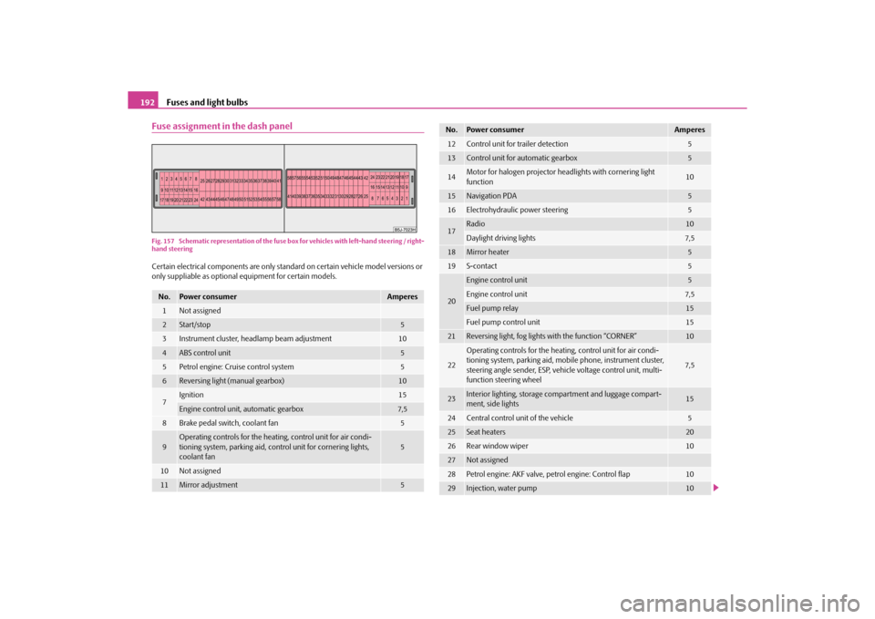
Fuse assignment in the dash panelFig. 157 Schematic representation of the fuse box for vehicles with left-hand steering / right-
hand steeringCertain electrical components are only standard on certain vehicle model versions or
only suppliable as optional equipment for certain models.No.
Power consumer
Amperes
1
Not assigned
2
Start/stop
5
3
Instrument cluster, headlamp beam adjustment
10
4
ABS control unit
5
5
Petrol engine: Cruise control system
5
6
Reversing light (manual gearbox)
10
7
Ignition
15
Engine control unit, automatic gearbox
7,5
8
Brake pedal switch, coolant fan
5
9
Operating controls for the heating, control unit for air condi-
tioning system, parking aid, control unit for cornering lights,
coolant fan
5
10
Not assigned
11
Mirror adjustment
5
12
Control unit for trailer detection
5
13
Control unit for automatic gearbox
5
14
Motor for halogen projector headlights with cornering light
function
10
15
Navigation PDA
5
16
Electrohydraulic power steering
5
17
Radio
10
Daylight driving lights
7,5
18
Mirror heater
5
19
S-contact
5
20
Engine control unit
5
Engine control unit
7,5
Fuel pump relay
15
Fuel pump control unit
15
21
Reversing light, fog lights with the function “CORNER”
10
22
Operating controls for the heating, control unit for air condi-
tioning system, parking aid, mobi le phone, instrument cluster,
steering angle sender , ESP, vehicle voltage control unit, multi-
function steering wheel
7,5
23
Interior lighting, storage compartment and luggage compart-
ment, side lights
15
24
Central control unit of the vehicle
5
25
Seat heaters
20
26
Rear window wiper
10
27
Not assigned
28
Petrol engine: AKF valve, petrol engine: Control flap
10
29
Injection, water pump
10
No.
Power consumer
Amperes
s16g.4.book Page 192 Wednesda y, February 10, 2010 3:53 PM
Page 195 of 231
Fuses and light bulbs
194
– Release the fixtures in the openings using a flat screwdriver and fold the cover
upwards in direction of arrow .
– Find out which fuse belongs to th e component which is not operating.
– Defect fuses can be detected by their melted metal strips. Replace the defect fuse by a new fuse of the same ampere number.
Caution
Never attempt to “repair” fuses and also do not replace them with a fuse of a higher
amperage - risk of fire! This may also cause damage at an other part of the electrical
system.
Have the electrical system checked as quickl y as possible by a specialist garage if a
newly inserted fuse blows again after a short time.Note
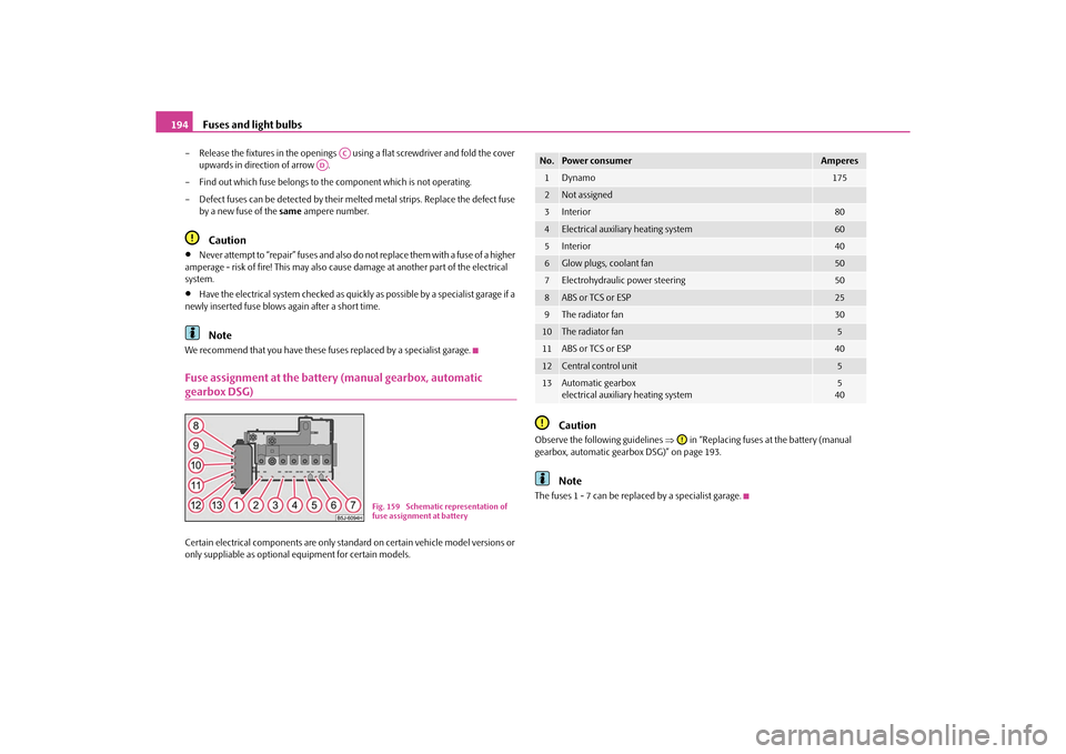
We recommend that you have these fuses replaced by a specialist garage.Fuse assignment at the battery (manual gearbox, automatic gearbox DSG)Certain electrical components are only standard on certain vehicle model versions or
only suppliable as optional equipment for certain models.
Caution
Observe the following guidelines in “Replacing fuses at the battery (manual
gearbox, automatic gearbox DSG)” on page 193.
Note
The fuses 1 - 7 can be replac ed by a specialist garage.
AC
AD
Fig. 159 Schematic representation of
fuse assignment at battery
No.
Power consumer
Amperes
1
Dynamo
175
2
Not assigned
3
Interior
80
4
Electrical auxiliary heating system
60
5
Interior
40
6
Glow plugs, coolant fan
50
7
Electrohydraulic power steering
50
8
ABS or TCS or ESP
25
9
The radiator fan
30
10
The radiator fan
5
11
ABS or TCS or ESP
40
12
Central control unit
5
13
Automatic gearbox
electrical auxiliary heating system
5
40
s16g.4.book Page 194 Wednesda y, February 10, 2010 3:53 PM
Page 196 of 231
Fuses and light bulbs195
Using the system
Safety
Driving Tips
General Maintenance
Breakdown assistance
Praktik
Technical Data
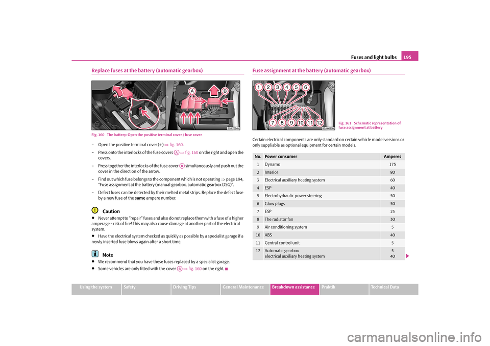
Replace fuses at the battery (automatic gearbox)Fig. 160 The battery: Open the posi tive terminal cover / fuse cover– Open the positive terminal cover (+) fig. 160 .
– Press onto the interlocks of the fuse covers fig. 160 on the right and open the
covers.
– Press together the interlocks of the fuse cover simultaneously and push out the
cover in the direction of the arrow.
– Find out which fuse belongs to th e component which is not operating page 194,
“Fuse assignment at the battery (ma nual gearbox, automatic gearbox DSG)”.
– Defect fuses can be detected by their melted metal strips. Replace the defect fuse by a new fuse of the same ampere number.
Caution
Never attempt to “repair” fuses and also do not replace them with a fuse of a higher
amperage - risk of fire! This may also cause damage at an other part of the electrical
system.
Have the electrical system checked as quickl y as possible by a specialist garage if a
newly inserted fuse blows again after a short time.Note
We recommend that you have these fuses replaced by a specialist garage.
Some vehicles are only fitted with the cover fig. 160 on the right.
Fuse assignment at the battery (automatic gearbox)Certain electrical components are only stan dard on certain vehicle model versions or
only suppliable as optional equipment for certain models.
AAABAB
No.
Power consumer
Amperes
1
Dynamo
175
2
Interior
80
3
Electrical auxiliary heating system
60
4
ESP
40
5
Electrohydraulic power steering
50
6
Glow plugs
50
7
ESP
25
8
The radiator fan
30
9
Air conditioning system
5
10
ABS
40
11
Central control unit
5
12
Automatic gearbox
electrical auxiliary heating system
5
40
Fig. 161 Schematic representation of
fuse assignment at battery
s16g.4.book Page 195 Wednesda y, February 10, 2010 3:53 PM