wheel SKODA SUPERB 2007 1.G / (B5/3U) User Guide
[x] Cancel search | Manufacturer: SKODA, Model Year: 2007, Model line: SUPERB, Model: SKODA SUPERB 2007 1.G / (B5/3U)Pages: 259, PDF Size: 14.71 MB
Page 86 of 259

Seats and Stowage85
Using the systemSafetyDriving TipsGeneral MaintenanceBreakdown assistanceTechnical Data
Storage compartment for spectacles*
The stowage compartment is located above the front left window.
– The storage compartment is opened by folding it out in the direction
of the arrow ⇒fig. 97 .
WARNING
The storage compartment must always be closed when driving for safety
reasons!
Stowage compartment below steering wheel
You can use this stowage compartment, for example, for inserting the car
documentation.
Stowage compartment in door panel
Fig. 97 Stowage
compartment for specta-
clesFig. 98 Dash panel:
Stowage compartments
below steering wheel
Fig. 99 Stowage
compartment in door
panel
NKO B5 20.book Page 85 Friday, March 2, 2007 1:46 PM
Page 93 of 259

Heating and air conditioning system
92
Switching recirculated air mode off
– Press button again, the button symbol
goes out.
Recirculated air mode is switched off automa tically or cannot be switched on, if the
air distributi on control ⇒ page 90, fig. 106 is in position .
WARNING
You should not leave recirculated air mode on over a longer period of time,
as “stale” air may result in fatigue in the driver and occupants, divert your
attention and also cause the windows to mist up. The risk of having an acci-
dent increases. Switch recirculated air mode off as soon as the windows
begin misting up.
Air outlet vents
Fig. 107 Air vents at the front Fig. 108 Air vents at the rear
Open air outlet vents
– Turn the vertical thumbwheel (not when in the end position).
Close air outlet vents
– Turn the vertical thumbwheel into the end position.
Redirecting air flow
– Swivel upward or downward the grille of the vents in order to change
the direction of the air flow using the vertically arranged thumbwheel.
– Turn the horizontal thumbwheel on the vent to the right or left in order to change the air flow to the appropriate side.
You can set the air supply to the individual vents with the air distribution control
⇒ page 90, fig. 106. You can also set the vents 3 and 4 ⇒ fig. 107 and 6 ⇒ fig. 108
individually.
Unwarmed or cooled air will flow out of th e air outlet vents according to the setting
of control dial ⇒page 90, fig. 106 and the atmospheric conditions.
The rear footwell vents 7 are controlled together with the vents 5. Turn the air distri-
bution control ⇒page 90, fig. 106 into the position
.
AC
AC
AA
AC
NKO B5 20.book Page 92 Friday, March 2, 2007 1:46 PM
Page 98 of 259

Heating and air conditioning system97
Using the systemSafetyDriving TipsGeneral MaintenanceBreakdown assistanceTechnical Data
If
OFF is shown in the display, this indicates that the Climatronic system is switched
off ⇒page 98.
WARNING
•“Stale air” may result in fatigue in the driver and occupants, reduce
attention levels and also cause the windows to mist up. The risk of having an
accident increases.
•Do not switch the Climatronic system off for longer than necessary.
•Switch the Climatronic system on as soon as the windows mist up.
Air outlet vents
Fig. 110 Air vents at the front Fig. 111 Air vents at the rear
You can also set the vents
3 and 4 ⇒ fig. 110 and 6 ⇒ fig. 111 individually.
Open air outlet vents
– Turn the vertical thumbwheel (not when in the end position).
Close air outlet vents
– Turn the vertical thumbwh eel into the end position.
Redirecting air flow
– Swivel upward or downward the grille of the vents in order to change the direction of the air flow using the vertically arranged thumbwheel.
– Turn the horizontal thumbwheel on the vent to the right or left in order to change the air flow to the appropriate side.
NKO B5 20.book Page 97 Friday, March 2, 2007 1:46 PM
Page 100 of 259
Starting-off and Driving99
Using the systemSafetyDriving TipsGeneral MaintenanceBreakdown assistanceTechnical Data
Starting-off and Driving
Setting steering wheel position
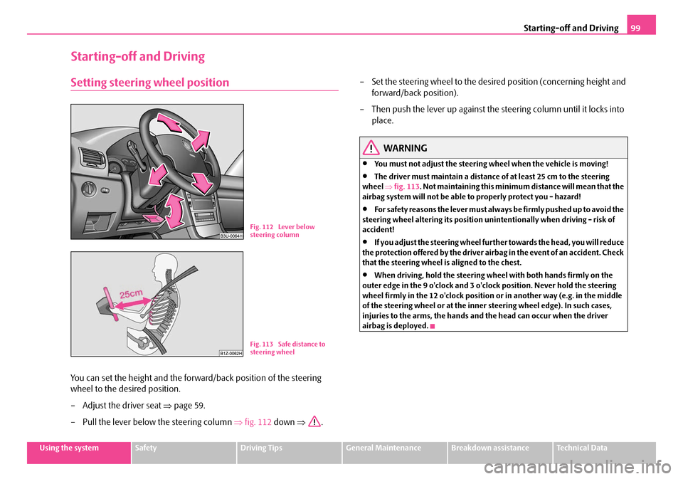
You can set the height and the forw ard/back position of the steering
wheel to the desired position.
– Adjust the driver seat ⇒page 59.
– Pull the lever below the steering column ⇒fig. 112 down ⇒. – Set the steering wheel to the desired position (concerning height and
forward/back position).
– Then push the lever up against the steering column until it locks into place.
WARNING
•You must not adjust the steering wh eel when the vehicle is moving!
•The driver must maintain a distance of at least 25 cm to the steering
wheel ⇒fig. 113 . Not maintaining this minimum distance will mean that the
airbag system will not be able to properly protect you - hazard!
•For s a fe t y re a s ons the le v e r m ust a lwa y s b e fi rm l y pus he d up t o a vo id the
steering wheel altering its position unintentionally when driving - risk of
accident!
•If you adjust the steering wheel furthe r towards the head, you will reduce
the protection offered by the driver airb ag in the event of an accident. Check
that the steering wheel is aligned to the chest.
•When driving, hold the steering wheel with both hands firmly on the
outer edge in the 9 o'clock and 3 o'clock position. Never hold the steering
wheel firmly in the 12 o'clock position or in another way (e.g. in the middle
of the steering wheel or at the inner steering wheel edge). In such cases,
injuries to the arms, the hands and the head can occur when the driver
airbag is deployed.
Fig. 112 Lever below
steering column
Fig. 113 Safe distance to
steering wheel
NKO B5 20.book Page 99 Friday, March 2, 2007 1:46 PM
Page 101 of 259

Starting-off and Driving
100
Ignition lock
Petrol engines
- ignition switched off, engine off
- ignition switched on
- start engine
Diesel engines - fuel supply interrupted, ignition switched off, engine off
- heating glow plugs on, ignition switched on
•You should not switch on any major elec trical components during the heating
period otherwise the vehicle batt ery will be drained unnecessarily.
- start engine
Applies to all models:
Position
To lock the steering , with the ignition key withdrawn, turn the steering wheel until
the steering locking pin is heard to engage. You should always lock the steering as
a general rule if you leave your vehicle. This acts as a deterrent against possible theft
of your vehicle ⇒.
Position Move the steering wheel back and forward a little if the ignition key cannot, or
cannot easily be turned into this position
, in order to release the steering lock.
Position
The engine is started in this position. At the same time switched on low beam or
main beam or other electrical compon ents with major power consumption are
briefly switched off. The ignition key moves back into position when one
releases the key.
The ignition key must be turned back into position each time before starting the
engine again. The starter repeat lock in th e ignition lock prevents the starter being
engaged when the engine is r unning and thus getting damaged.
Ignition key withdrawal lock (automatic gearbox)
You can only withdraw the ignition key after switching off the ignition if the selector
lever is in position P.
WARNING
•When driving, the ignition key must always be in the position (igni-
tion switched on) without the engine running. This position is indicated by
the warning lights coming on. If this is not the case, it could result in unex-
pected locking of the steerin g wheel - risk of accident!
•Only remove the ignition key from the ignition lock when the vehicle has
come to a standstill (put on the handbrake or select the selector lever posi-
tion P). The steering lock can enga ge immediately - risk of accident!
•Always withdraw the ignition key if you are going to leave the vehicle,
even for a short time. This is particularly important if children are left in the
vehicle. The children might otherwise st art the engine or operate electrical
equipment (e.g. power windows) - risk of injury!
Fig. 114 Ignition lock
positions
A1
A2
A3
A1
A2
A3
A1
A2
A3
A2
A1
A2
NKO B5 20.book Page 100 Friday, March 2, 2007 1:46 PM
Page 111 of 259
Automatic gearbox*
110
Selector lever positions
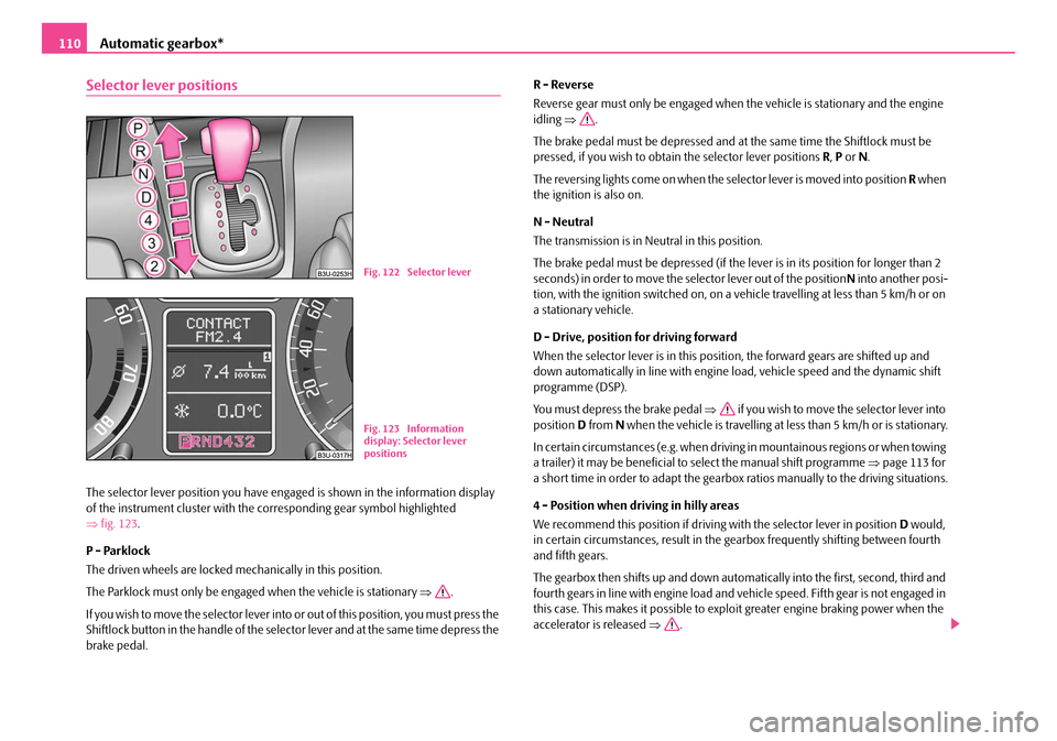
The selector lever position you have engaged is shown in the information display
of the instrument cluster with the co rresponding gear symbol highlighted
⇒ fig. 123 .
P - Parklock
The driven wheels are locked mechanically in this position.
The Parklock must only be engaged when the vehicle is stationary ⇒.
If you wish to move the select or lever into or out of this position, you must press the
Shiftlock button in the handle of the select or lever and at the same time depress the
brake pedal. R - Reverse
Reverse gear must only be engaged when
the vehicle is stationary and the engine
idling ⇒ .
The brake pedal must be depressed and at the same time the Shiftlock must be
pressed, if you wish to obtain the selector lever positions R, P or N.
The reversing lights come on when the selector lever is moved into position R when
the ignition is also on.
N - Neutral
The transmission is in Neutral in this position.
The brake pedal must be depressed (if the lever is in its position for longer than 2
seconds) in order to move the selector lever out of the position N into another posi-
tion, with the ignition switched on, on a vehicle travelling at less than 5 km/h or on
a stationary vehicle.
D - Drive, position for driving forward
When the selector lever is in this position, the forward gears are shifted up and
down automatically in line with engine load, vehicle speed and the dynamic shift
programme (DSP).
You must depress the brake pedal ⇒ if you wish to move the selector lever into
position D from N when the vehicle is travelling at less than 5 km/h or is stationary.
In certain circumstances (e.g. when driving in mountainous regions or when towing
a trailer) it may be beneficial to select the manual shift programme ⇒page 113 for
a short time in order to adapt the gearbox ratios manually to the driving situations.
4 - Position when driving in hilly areas
We recommend this position if driving with the selector lever in position D would,
in certain circumstances, result in the gearbox frequently shifting between fourth
and fifth gears.
The gearbox then shifts up and down automa tically into the first, second, third and
fourth gears in line with engine load and vehicle speed. Fifth gear is not engaged in
this case. This makes it possible to expl oit greater engine braking power when the
accelerator is released ⇒.
Fig. 122 Selector lever
Fig. 123 Information
display: Selector lever
positions
NKO B5 20.book Page 110 Friday, March 2, 2007 1:46 PM
Page 113 of 259
Automatic gearbox*
112
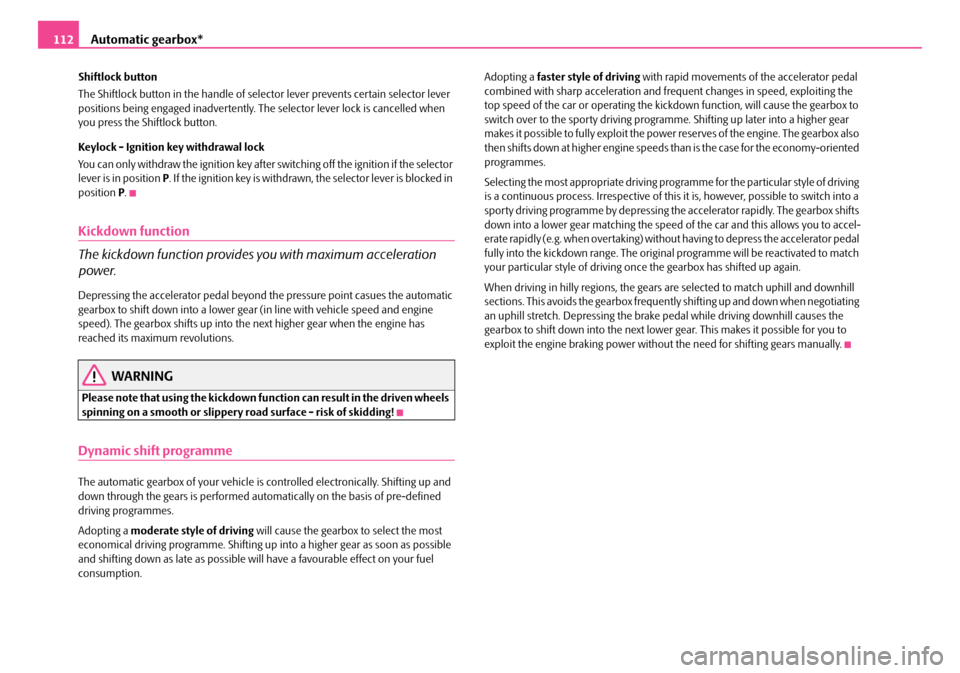
Shiftlock button
The Shiftlock button in the handle of select or lever prevents certain selector lever
positions being engaged inadvertently. The selector lever lock is cancelled when
you press the Shiftlock button.
Keylock - Ignition key withdrawal lock
You can only withdraw the ignition key after switching off the ignition if the selector
lever is in position P. If the ignition key is withdrawn, the selector lever is blocked in
position P.
Kickdown function
The kickdown function provides you with maximum acceleration
power.
Depressing the accelerator pedal beyond the pressure point casues the automatic
gearbox to shift down into a lower gear (in line with vehicle speed and engine
speed). The gearbox shifts up into the next higher gear when the engine has
reached its maximum revolutions.
WARNING
Please note that using the kickdown fu nction can result in the driven wheels
spinning on a smooth or slippery road surface - risk of skidding!
Dynamic shift programme
The automatic gearbox of your vehicle is controlled electronically. Shifting up and
down through the gears is performed auto matically on the basis of pre-defined
driving programmes.
Adopting a moderate style of driving will cause the gearbox to select the most
economical driving programme. Shifting up into a higher gear as soon as possible
and shifting down as late as possible will have a favourable effect on your fuel
consumption. Adopting a
faster style of driving with rapid movements of the accelerator pedal
combined with sharp acceleration and freq uent changes in speed, exploiting the
top speed of the car or operating the kick down function, will cause the gearbox to
switch over to the sporty driving programme. Shifting up later into a higher gear
makes it possible to fully exploit the powe r reserves of the engine. The gearbox also
then shifts down at higher engine speeds than is the case for the economy-oriented
programmes.
Selecting the most appropriate driving programme for the particular style of driving
is a continuous process. Irrespective of this it is, however, possible to switch into a
sporty driving programme by depressing the accelerator rapidly. The gearbox shifts
down into a lower gear matching the speed of the car and this allows you to accel-
erate rapidly (e.g. when overtaking) without having to depress the accelerator pedal
fully into the kickdown range. The original programme will be reactivated to match
your particular style of driving once the gearbox has shifted up again.
When driving in hilly regions, the gears are selected to match uphill and downhill
sections. This avoids the gearbox frequently shifting up and down when negotiating
an uphill stretch. Depressing the brake pedal while driving downhill causes the
gearbox to shift down into the next lower gear. This makes it possible for you to
exploit the engine braking power withou t the need for shifting gears manually.
NKO B5 20.book Page 112 Friday, March 2, 2007 1:46 PM
Page 116 of 259

Communicating and Navigating115
Using the systemSafetyDriving TipsGeneral MaintenanceBreakdown assistanceTechnical Data
Communicating and Navigating
Multifunction steering wheel*
Introduction
The assignment of the pushbuttons in the steering wheel may differ depending on
the vehicle equipment.
The buttons , , and ⇒fig. 126 make it possible to operate the main
functions of the cruise control system, of the radio and mobile phone. Refer to the
more detailed information in the relevant operating instructions.
f the headlights are switched on, the bu ttons in the steering wheel come on.
Operating cruise control system
The cruise control system is operated with the buttons and , but on
version which is also fitted with mobile phone only by button
⇒fig. 126 . Switching on and off
– The cruise control system is
switched on by sliding the switch
⇒ page 106 into the ON position.
– The cruise control system is switched off by sliding the switch fully
to the right into the OFF position.
Storing a speed
– Switch the cruise control system on.
– After the car has reached the desired speed, briefly press the button ⇒ fig. 126 in the position SET-. The car maintains the stored speed
without you having to depress the accelerator pedal.
Changing a stored speed
– You can reduce the stored speed by pressing the button ⇒fig. 126
in the position SET-. If you press and hold the button, the speed of the
car is reduced continuously. Once the car has reached the desired
speed, release the rocker button. The set speed is then stored in the
memory.
– If you release the rocker button when the car is travelling at a speed of
less than 30 km/h, the speed is not stored, the memory is erased. It is
then necessary to again store the speed with the button in the
position SET
after an increase in speed of the vehicle to more than
30 km/h.
–You can increase the stored speed by pressing the button in the
position RES+. Pressing and holding down the slide switch will cause
the speed of the vehicle to be increased continuously. Once the car
has reached the desired speed, release the rocker button. The set
speed is then stored in the memory.
Fig. 126 Multifunction
steering wheel: control
buttons
A1A2A3A4
A1A2
A1
AA
AA
A1
A1
A1
A1
NKO B5 20.book Page 115 Friday, March 2, 2007 1:46 PM
Page 117 of 259

Communicating and Navigating
116
Switching off the cruise control system temporarily
– On the version not fitted with a mobile phone, the cruise control system is switched off temporarily with the button ⇒page 115,
fig. 126 in the position CANCEL, on the version fitted with mobile
phone, by pushing the switch into the intermediate position ahead
of the position OFF ⇒ page 107.
– You can resume the stored speed by pressing the button in the position RES+.
For further methods of temporarily swit ching off the cruise control system
⇒ page 107.
Please refer to the following guidelines ⇒ page 106.
WARNING
First ensure that it is not too high for the traffic conditions which exist at that
moment before resuming the stored speed.
Operating radio and CD player
The radio is operated with buttons and , but on the version fitted
with a mobile phone by buttons , and ⇒page 115, fig. 126 .
Radio
– You can set the radio, cassette player, CD player and radio data system louder or softer by pressing button (positions
and .
– You can search forward or back within the frequency search for different radio stations by pressing button (positions
and ).
Cassette player
– You can run the tape forward or back by pressing the button (posi- tions
and ). CD-player
– You can select the titles forward or back by pressing the button
(positions
and ).
Radio data system (RDS)*
You can select the recorded radio traffic messages by moving forward or back in
stages by pressing th e button (positions
and ).
On the version fitted with mobile phone, you must press button in the position
MODE in order to switch over to the radio mode.
Operating mobile phone
– You can operate the mobile phone with buttons , and
⇒fig. 127 .
– You can switch over from the radio mode to the phone mode (or back again) by pressing the bu tton in the position MODE.
– You can accept or end a telephone call or select from the phonebook
by briefly pressing the button in the position
.
– You can refuse a telephone call by pressing the button in the posi- tion
for more than 2 seconds.
A2
AA
A1
A3A4
A2A3A4
A3
A4
A4
A4
A4
A2
Fig. 127 Multifunction
steering wheel: control
buttons
A2A3A4
A2
A2
A2
NKO B5 20.book Page 116 Friday, March 2, 2007 1:46 PM
Page 118 of 259

Communicating and Navigating117
Using the systemSafetyDriving TipsGeneral MaintenanceBreakdown assistanceTechnical Data
– You can make the volume of the te lephone call louder or softer by
pressing the button in the position
or
– You call scroll through the telephone memory for names by briefly pressing the button in the position
or .
– You can scroll alphabetically upward (A to Z) or downward (Z to A)
within the telephone memory by pressing for some considerable time
the button in the position
and .
If you switch over with the button MODE on the multifunction steering wheel
⇒ page 116, fig. 127 to phone mode and the mobile phone is not in the adapter,
INSERT PHONE appears in the display. After inserting the mobile phone,
PHONE IN appears on the display.
Afterwards PHONE STARTUP appears on the display an d the system transmits the
data from the mobile phone to the information display. The following is shown one
after the other on the display:
•DIALED CALLS LOADING: xxx
•RCVD CALLS LOADING: xxx
•MISSED CALLS LOADING: xxx
•PHONEBOOK LOADING
One cannot scroll through the phonebook du ring data transfer out of the mobile
phone. After the data transfer has ended, the first name out of the phonebook is
shown on the display
You can scroll through the individual menus by pressing the button in the posi-
tion
or ⇒ page 116, fig. 127 .
Select the entry you want by pressi ng the button in the position
.
You will reach one level higher in the me nu by pressing the button in the posi-
tion MODE .
In the main menu you can select the following entries:
•PHONEBOOK
•SETUP
•LAST CALLS
•RECEIVED CALLS
•MISSED CALLS
In the menu SETUP you can select the following entries:
•LANGUAGE - Here you can set in which la nguage the messages should be
displayed. You can select one of the following languages: Czech, English, German,
Italian, French, Spanish. The set language is displayed inversely.
•MEMORY - Here you can set which telephon e memory should be transmitted
into the information display after insertin g the mobile phone in the adapter. You
can choose between the phonebook PHONE PHONEBOOK and the memory of
the SIM card SIM PHONEBOOK The set memory is displayed inversely.
•Certain mobile phones do not have any phone phonebook, but only a phone-
book in the memory of the SIM card.
•Overview of the next possible functions and read outs:
A3
A4
A4
A4
A2
A2
ActivityRead out in display
Selected call numberCALLING name
or
CALLING number
accepted callCALL name or
CALL number
or
CALL
Call rejectedCALL REJECTED
Call terminatedEND OF CALL
Number engagedLINE ENGAGED
No service foundNO SERVICE
Enter PIN codeENTER PIN CODE
NKO B5 20.book Page 117 Friday, March 2, 2007 1:46 PM