remove seats SKODA SUPERB 2007 1.G / (B5/3U) Owner's Manual
[x] Cancel search | Manufacturer: SKODA, Model Year: 2007, Model line: SUPERB, Model: SKODA SUPERB 2007 1.G / (B5/3U)Pages: 259, PDF Size: 14.71 MB
Page 64 of 259

Seats and Stowage63
Using the systemSafetyDriving TipsGeneral MaintenanceBreakdown assistanceTechnical Data
Retrieving setting of exterior mirror for reversing*
– Turn the rotary knob for the exterior mirror setting into the position
⇒ page 57 before engaging the reverse gear.
Emergency Off
You can interrupt any memory retrieval operation in an emergency by pressing the
switch ⇒page 61, fig. 55 , by one-touch of a memory button or by pressing the
seat setting switch.
Head restraints
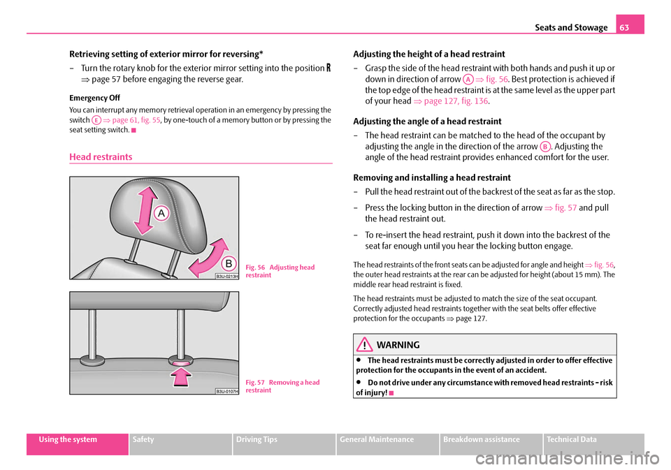
Adjusting the height of a head restraint
– Grasp the side of the head restraint with both hands and push it up or down in direction of arrow ⇒fig. 56 . Best protection is achieved if
the top edge of the head restraint is at the same level as the upper part
of your head ⇒page 127, fig. 136 .
Adjusting the angle of a head restraint
– The head restraint can be matched to the head of the occupant by
adjusting the angle in the direction of the arrow . Adjusting the
angle of the head restraint provides enhanced comfort for the user.
Removing and installing a head restraint
– Pull the head restraint out of the backrest of the seat as far as the stop.
– Press the locking button in the direction of arrow ⇒fig. 57 and pull
the head restraint out.
– To re-insert the head restraint, push it down into the backrest of the
seat far enough until you hear the locking button engage.
The head restraints of the front seats can be adjusted for angle and height ⇒fig. 56 ,
the outer head restraints at the rear can be adjusted for height (about 15 mm). The
middle rear head restraint is fixed.
The head restraints must be adjusted to match the size of the seat occupant.
Correctly adjusted head restraints together with the seat belts offer effective
protection for the occupants ⇒page 127.
WARNING
•The head restraints must be correctly adjusted in order to offer effective
protection for the occupants in the event of an accident.
•Do not drive under any circumstance with removed head restraints - risk
of injury!
AE
B1Z-0042HB1Z-0042HFig. 56 Adjusting head
restraint
B1Z-0042HB1Z-0042HFig. 57 Removing a head
restraint
AA
AB
NKO B5 20.book Page 63 Friday, March 2, 2007 1:46 PM
Page 74 of 259

Seats and Stowage73
Using the systemSafetyDriving TipsGeneral MaintenanceBreakdown assistanceTechnical Data
The cool box behind the armrest of the rear seats*
Using the system
The contents of the cool box is cool ed to a temperature of about 20 °C
below the ambient temperature, but to a maximum of approx.+ 5 °C.
Opening and Closing
– Pull the handle ⇒fig. 74 and pull the lid downwards.
– Open up the lid of the cool box upwards until it is heard to lock.
Switching on and off
– The cooling action of the cool box is switched on and off using switch
⇒ fig. 74 . It is signalised by the lighting up of the indicator light on
the switch.
You can remove the cool box if necessary ⇒page 74. You can replace the cool box
with a storage net ⇒fig. 75 .
Caution
Never cover the ventilator on the cool box otherwise it will overheat and could be
damaged.
Note
The cool box also operates if the ignition is switched off. The battery will not run
down fully, however, since the system is fitted with a device which monitors the
battery charge level. The cool box will be automatically switched off when it is
threatening to empty the battery.
Partition with storage net
If the cool box is removed, install the partition with the storage net
⇒ fig. 75 which is fixed with a velcro fastener to the side wall of the cool
box.
– The partition is installed and removed in a similar way to the cool box ⇒page 74.
Fig. 74 Cool box
AA
Fig. 75 Partition with
storage net
NKO B5 20.book Page 73 Friday, March 2, 2007 1:46 PM
Page 75 of 259

Seats and Stowage
74
Removing and installing the cool box
Removing
– Switch the cooling mode of the cool box off ⇒page 73.
– Remove the locking mechanism ⇒fig. 76 .
– Open the lid of the cool box.
– Press open the upper side of the cool box from the inside in the direc- tion of arrow and put away the cool box in the luggage compart-
ment (see arrow ). – Unplug the plug connector (the pl
ug connector is located in the
luggage compartment in the lower part of the fixing frame for the cool
box).
Installing
– Place the cool box on the luggage compartment partition and plug in the plug.
– Remove the locking mechanism ⇒fig. 76 .
– Fold the lid of the cool box onto the fixing frame ⇒fig. 77 .
– Lift the cool box with the palm of the hand on the inside of the upper wall of the cool box.
– Insert the cool box with the lower edge into the lower holding bracket on the luggage compartment partition.
– Pull the cool box forwards to the upper edge until the stop (see arrow ), press with the palm of the hand onto the upper wall (see arrow
), pull the box again forwards and press downwards (see arrow ).
– Push the locking mechanism ⇒fig. 76 u p t o t h e s t o p i n t o t h e f i x i n g
frame.
– Close the lid of the cool box.
Fig. 76 Removing the
cool box
Fig. 77 Installing the
cool box
AA
A1
A2
AA
A1
A2A3
AA
NKO B5 20.book Page 74 Friday, March 2, 2007 1:46 PM
Page 76 of 259

Seats and Stowage75
Using the systemSafetyDriving TipsGeneral MaintenanceBreakdown assistanceTechnical Data
CargoFlex folding box*
Lowering and securing folding box
You can transport the folding box in two different positions - in the trans-
port position against the partition ⇒fig. 78 of the luggage compartment,
or in the ready position lowered onto the floor of the luggage compart-
ment ⇒fig. 79 .
Lowering folding box into the ready position
– Pull the snap handle in direction of arrow 1 ⇒ fig. 78 . The folding box
is lowered to just above the floor of the luggage compartment. – Press the folding box at the arrow positions
2 ⇒ fig. 79 onto the floor
of the luggage compartment until it locks in place. If correctly locked,
the snap handle moves back into its initial position (the top red
surface of the handle is not visible).
Securing folding box in the transport position against partition of
luggage compartment
– Lower the folding box into the ready position ⇒page 77.
– Pull the snap handle in direction of arrow 1 ⇒ fig. 78 . The folding box
is raised up from the luggage compartment floor.
– Raise and press the folding box against the partition of the luggage compartment, it is secured audibly in this way in the transport posi-
tion. If correctly locked, the snap handle moves back into its initial
position (the top red surface of the handle is not visible).
Opening folding box ⇒page 76.
Caution
•The parts of the folding box can be dama ged if handled roughly or in an unpro-
fessional way.
•Before you lower the folding box B into the ready position ⇒fig. 79 , it is neces-
sary to remove the net*, in order to avoid net damage.
B1Z-0042HB1Z-0042HFig. 78 Folding box:
Transport position
Fig. 79 Folding box:
ready position
NKO B5 20.book Page 75 Friday, March 2, 2007 1:46 PM
Page 82 of 259

Seats and Stowage81
Using the systemSafetyDriving TipsGeneral MaintenanceBreakdown assistanceTechnical Data
Cigarette lighters and power sockets
Cigarette lighter
You can also use the socket on th e cigarette lighter for other elec-
trical appliances.
Using the cigarette lighter
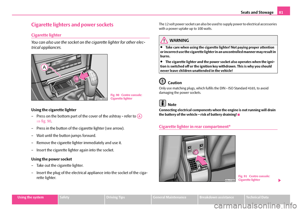
– Press on the bottom part of the cover of the ashtray - refer to
⇒fig. 90 .
– Press in the button of the cigarette lighter (see arrow).
– Wait until the button jumps forward.
– Remove the cigarette lighter immediately and use it.
– Insert the cigarette lighter again into the socket.
Using the power socket
– Take out the cigarette lighter.
– Insert the plug of the electrical a ppliance into the socket of the ciga-
rette lighter.
The 12 volt power socket can also be used to supply power to electrical accessories
with a power uptake up to 100 watts.
WARNING
•Take care when using the cigarette li ghter! Not paying proper attention
or incorrect use the cigarette lighter in an uncontrolled manner may result in
burns.
•The cigarette lighter and the power so cket also operates when the igni-
tion is switched off or the ignition key withdrawn. This is why you should
never leave children unattended in the vehicle!
Caution
Only use matching plugs, which fulfils the DIN - ISO Standard 4165, to avoid
damaging the power sockets.
Note
Connecting electrical components when the engine is not running will drain
the battery of the vehicle - risk of battery draining!
Cigarette lighter in rear compartment*
Fig. 90 Centre console:
Cigarette lighter
AA
B1Z-0042HB1Z-0042HFig. 91 Centre console:
Cigarette lighter
NKO B5 20.book Page 81 Friday, March 2, 2007 1:46 PM
Page 87 of 259

Seats and Stowage
86
WARNING
Use the stowage compartments in the door panels only for small items
which do not project out of the compartment in order to avoid any interfer-
ence with the proper operation of the side airbags.
Stowage compartment for umbrella*
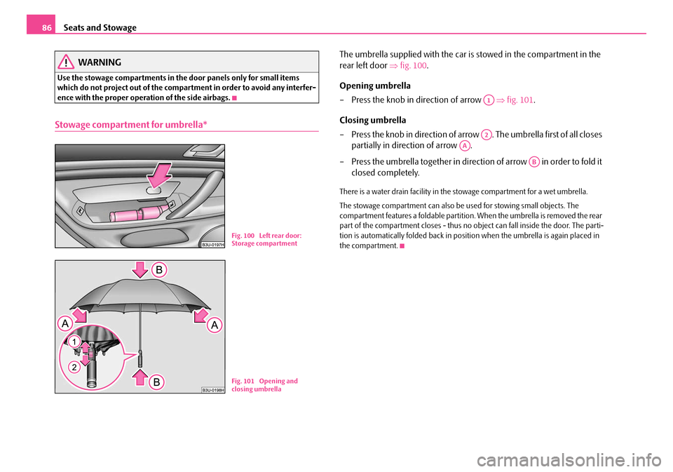
The umbrella supplied with the car is stowed in the compartment in the
rear left door ⇒fig. 100 .
Opening umbrella
– Press the knob in direction of arrow ⇒fig. 101 .
Closing umbrella
– Press the knob in direction of arrow . The umbrella first of all closes partially in direction of arrow .
– Press the umbrella together in direction of arrow in order to fold it closed completely.
There is a water drain facility in the stowage compartment for a wet umbrella.
The stowage compartment can also be used for stowing small objects. The
compartment features a foldable partition. When the umbrella is removed the rear
part of the compartment closes - thus no object can fall inside the door. The parti-
tion is automatically folded back in position when the umbrella is again placed in
the compartment.
B1Z-0042HB1Z-0042HFig. 100 Left rear door:
Storage compartment
Fig. 101 Opening and
closing umbrella
A1
A2
AA
AB
NKO B5 20.book Page 86 Friday, March 2, 2007 1:46 PM
Page 133 of 259

Seat belts
132
•No two persons (also not children) should ever use a single seat belt
together.
•The maximum protection which seat belts can offer is only achieved if
you are correctly seated ⇒page 127, “Correct seated position”.
•The belt webbing must no t run across solid or fragile objects (e.g. spec-
tacles, ball-point pens, keys etc.) as this may be a cause of injuries.
•Bulky, loose clothing (e.g. a winter coat over a jacket) does not allow you
to be correctly seated and impairs proper operation of the seat belts.
•It is prohibited to use clamps or other objects to adjust seat belts (e.g. for
shortening the belts for smaller persons).
•The lock tongue should only be insert ed into the lock which is the correct
one for your seat. Wrong use of the safety belt will reduce its capacity to
protect and the risk of injury increases.
•The backrests of the front seats must not be tilted too far to the rear
otherwise the seatbelts can lose their effectiveness.
•The belt webbing must always be ke pt clean. Soiled belt webbing may
impair proper operation of the inertia reel ⇒page 179, “Seat belts”.
•The slot of the belt tongue must not be blocked by paper or similar
objects otherwise the belt tongue will not lock in place properly.
•Inspect the seat belts regularly to ensure they are in good condition. If
you find seat belts which have damage to the seat belt webbing, seat belt
connections, to the inertia reels or to the lock, the relevant safety belt must
be replaced by a specialist garage.
•The seat belts must not be removed or changed in any way. Do not make
an attempt to repair the seat belts yourself.
•Damaged seat belts which have been subjected to stress in an accident
and were therefore stretched, must be replaced - this is best done by a
specialist garage. The anchorage points of the belts must also be inspected.
The anchorage points for the be lts should also be checked.
•In certain countries it is possible to use seat belts which differ in terms of
their operation from the seat belts which are described on the pages which
follow.
How are seat belts correctly fastened?
Fastening three-point seat belts
Fasten your seat belt before starting!
– Correctly adjust the front seat and the head restraint before fastening
your seat belt ⇒page 127, “Correct seated position”.
WARNING (continued)
Fig. 140 Routing of
webbing over the shoul-
ders and the lap belt
Fig. 141 Routing of belt
webbing for an expectant
mother
NKO B5 20.book Page 132 Friday, March 2, 2007 1:46 PM
Page 223 of 259

Fuses and light bulbs
222
The power windows and the power seats are protected by automatic circuit
breakers which switch on again automatically after a few seconds after the over-
load has been eliminated - e.g. frozen windows.
Bulbs
Changing bulbs
The relevant lamp must always be switch ed off before a light bulb is replaced.
Do not take hold of the glass bulb with naked fingers (even the smallest amount of
dirt reduces the working life of the light bu lb). Use a clean cloth, serviette or some-
thing similar. Defect light bulbs should only be replaced
with light bulbs of the same type. The
designation is located on the li ght socket or the glass bulb.
Changing certain bulbs is not something wh ich you can do yourself, but requires to
be done by a specialist. Other parts of the vehicle must be removed in order to
change the light bulbs. This applies, in particular, to bulbs which can only be
reached from the engine compartment.
We therefore recommend that you have any bulbs changed by a Škoda Service
Partner or, in exceptional cases, by ca lling on other professional assistance.
Please note that the engine compartment is a hazardous area ⇒page 185,
“Working in the engine compartment”.
We recommend that you carry the set of light bulbs with you which was delivered
in your vehicle. Replacement light bulbs
7) are available at specialist garages.
Fitted with a xenon headlight
Change of light bulbs on Xenon lights (low beam lights, parking lights and main
beam lights) should be undertaken by a specialist garage.
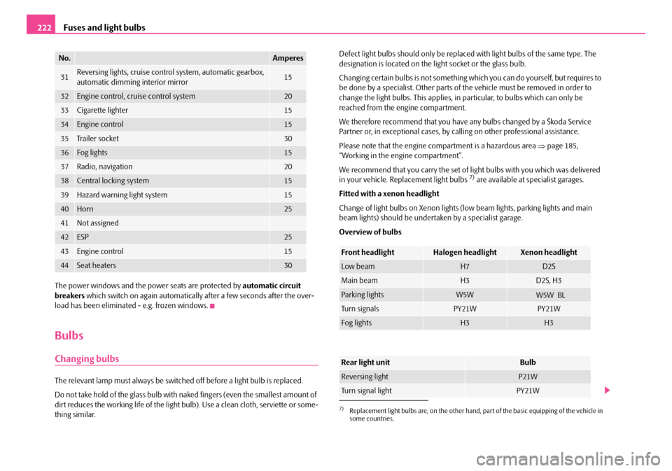
Overview of bulbs
31Reversing lights, cruise control system, automatic gearbox,
automatic dimming interior mirror15
32Engine control, cruise control system20
33Cigarette lighter15
34Engine control15
35Tr a i l e r s o c k e t30
36Fog lights15
37Radio, navigation20
38Central locking system15
39Hazard warning light system15
40Horn25
41Not assigned
42ESP25
43Engine control15
44Seat heaters30
No.Amperes
7)Replacement light bulbs are, on the other hand, part of the basic equipping of the vehicle in
some countries.
Front headlightHalogen headlightXenon headlight
Low beamH7D2S
Main beamH3D2S, H3
Parking lightsW5W
Tu r n s i g n a l sPY21WPY21W
Fog lightsH3H3
Rear light unitBulb
Reversing lightP21W
Turn signal lightPY21W
NKO B5 20.book Page 222 Friday, March 2, 2007 1:46 PM
W5W L
B