warning light SKODA SUPERB 2010 2.G / (B6/3T) Owner's Manual
[x] Cancel search | Manufacturer: SKODA, Model Year: 2010, Model line: SUPERB, Model: SKODA SUPERB 2010 2.G / (B6/3T)Pages: 287, PDF Size: 16.59 MB
Page 222 of 287
Inspecting and replenishing221
Using the system
Safety
Driving Tips
General Maintenance
Breakdown assistance
Technical Data
If any splashes of coolant get into yo ur eyes, rinse out your eyes immedi-
ately with clear water and contact a doctor as soon as possible.
You should also consult a doctor without delay if you have inadvertently
swallowed coolant.Caution
Do not continue your journey if for some reason it is not possible under the
conditions prevailing to top up with coolant. Switch the engine off and obtain
professional assistance from a specialist garage, otherwise it could lead to severe
engine damage.
For the sake of the environment
Do not re-use coolant if it is necessary to drain the coolant in the system. It should be
collected and disposed of in compliance with environmental protection regulations.Radiator fan
The radiator fan may switch on suddenly.The radiator fan is driven by an electric motor and controlled according to the coolant
temperature.
The radiator fan may continue running for up to 10 minutes after the engine has been
switched off - even if the igni tion is also off. It may also switch on suddenly after a
certain time, if.
the coolant temperature has risen beca use of an accumulation of heat or
the warm engine compartment is heated up additionally by strong sunlight.
WARNING
You must therefore be aware when workin g in the engine compartment that the
fan may switch on suddenly - risk of injury!
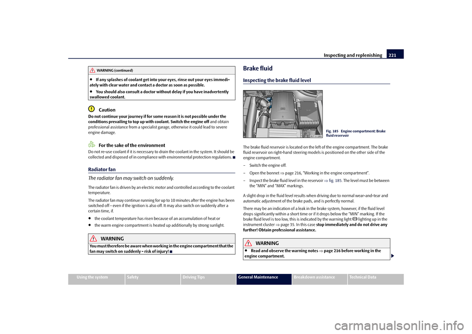
Brake fluidInspecting the brake fluid levelThe brake fluid reservoir is located on the left of the engine compartment. The brake
fluid reservoir on right-hand steering models is positioned on the other side of the
engine compartment.
– Switch the engine off.
– Open the bonnet page 216, “Working in the engine compartment”.
– Inspect the brake fluid level in the reservoir fig. 185 . The level must be between
the “MIN” and “MAX” markings.
A slight drop in the fluid level results when driving due to normal wear-and-tear and
automatic adjustment of the brak e pads, and is perfectly normal.
There may be an indication of a leak in the brake system, however, if the fluid level
drops significantly within a short time or if it drops below the “MIN” marking. If the
brake fluid level is too low, this is indicated by the warning light
lighting up in the
instrument cluster page 35. In this case stop immediately and do not drive any
further! Obtain professional assistance.
WARNING
Read and observe the warning notes page 216 before working in the
engine compartment.
WARNING (continued)
Fig. 185 Engine compartment: Brake
fluid reservoir
s3fg.2.book Page 221 Friday, April 30, 2010 12:17 PM
Page 224 of 287
Inspecting and replenishing223
Using the system
Safety
Driving Tips
General Maintenance
Breakdown assistance
Technical Data
There is a risk of injuries, scalding, accidents and burns when carrying out any work on
the battery and on the electrical system. For
this reason, it is essential to comply with
the warning instructions stated below and with the general applicable rules of
safety.
WARNING
The battery acid is strongly corrosive and must, therefore, be handled with
the greatest of care. Always wear prot ective gloves, eye and skin protection
when handling batteries. Corrosive fumes in the air irritate the air passages and
lead to conjunctivitis and inflammation of the air passages in the lungs. Battery
acid corrodes dental enamel and create s deep wounds after contact with the
skin which take a long time to heal. Repeated contact with diluted acids causes
skin diseases (inflammations, ulcers, slin cracks). Acids coming into contact
with water are diluted accompanied by significant development of heat.
Do not tilt the battery otherwise battery electrolyte may flow out of the
battery vent openings. Protect the eyes with safety glas ses or a shield! There is
the danger of suffering blindness! If an y battery electrolyte gets into your eye,
rinse out your eye immediately with cl ear water for several minutes. Contact a
doctor without delay.
Splashes of acid on your skin or clothes should be neutralised as soon as
possible using soap suds and then rinsed with plenty of water. Contact a doctor
immediately if you swal low battery electrolyte.
Keep batteries out of the reach of children.
Hydrogen is released when you charge a battery and a highly explosive gas
mixture is produced. An explosion can be caused through sparkling over during
unclamping or loosening of the cabl e plug while the ignition is on.
Bridging of the poles will create a short circuit (e.g. through metal objects,
cables). Possible consequences of a short circuit: Melting of lead struts, explo-
sion and burning of the battery, jets of acid spurting out.
It is prohibited to work with a naked flame and light, to smoke or to carry out
any activities which produce sparks. Avoi d creating sparks when working with
cables and electrical devices. Strong sparking represents a risk of injury.
Before carrying out any work on the el ectrical system, switch off the engine,
the ignition as well as all electrical components and disconnect the negative cable (-) on the battery. If you wish to replace a bulb it is sufficient to switch off
the appropriate light.
Never charge a frozen or thawed battery - risk of explosion and caustic
burns! Replace a frozen battery.
Never jump-start the batteries which ha ve a too low electrolyte level - risk
of explosion and caustic burns.
Never use a battery which is damaged - risk of explosion! Immediately
replace a damaged battery.Caution
You must only disconnect the battery if th e ignition is switched off, otherwise the
electrical system (electronic components ) of the vehicle may be damaged. When
disconnecting the battery from the electrical system of the vehicle, first disconnect the
negative terminal (-) of the battery. Then disconnect the positive terminal (+).
When reconnecting the battery, first connect the positive terminal (+) and only
then the negative terminal (-) of the battery. You must on no account connect the
cables wrongly - risk of a cable fire.
Ensure that battery acid does not come into contact with the vehicle body other-
wise damage could occur to the paintwork.
Do not place the battery in direct daylight in order to protect the battery housing
from the effects of ultra-violet light.For the sake of the environment
A removed battery is a special type of wa ste which is harmful to the environment -
contact your specialist garage regarding disposing of the battery.
Note
Please also refer to the guidelines page 226, also after connecting the battery.
WARNING (continued)
s3fg.2.book Page 223 Friday, April 30, 2010 12:17 PM
Page 227 of 287
Inspecting and replenishing
226
Disconnecting and reconnecting the batteryOn disconnecting and reconnecting the batt ery the following functions are initially
deactivated or are no longer able to operate fault-free:
We recommend having the vehi cle checked by an authorised Škoda Service Partner to
ensure full functionality of all electrical systems.Replacing the batteryYou should only replace a battery with a ne w battery of the same capacity, voltage (12
V), amperage and of the same size. The auth orised Škoda Service Partners have a range
of suitable batteries available.
For the sake of the environment
Batteries contain poisonous substances such as sulphuric acid and lead. They must be
disposed of in accordance with local environmental protection regulations and on no
account as domestic waste!
In view of the problems involved with it s proper disposal, we recommend having
the battery replaced by a specialist garage.
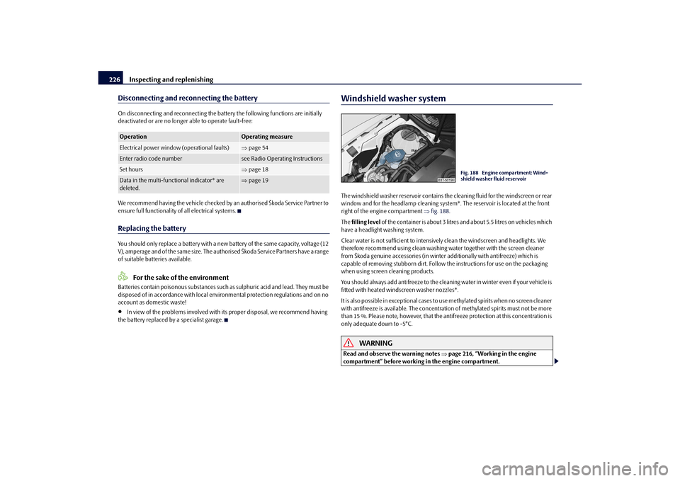
Windshield washer systemThe windshield washer reservoir contains the cleaning fluid for the windscreen or rear
window and for the headlamp cleaning system *. The reservoir is located at the front
right of the engine compartment fig. 188 .
The filling level of the container is about 3 litres and about 5.5 litres on vehicles which
have a headlight washing system.
Clear water is not sufficient to intensively clean the windscreen and headlights. We
therefore recommend using clean washing water together with the screen cleaner
from Škoda genuine accessories (in winter additionally with antifreeze) which is
capable of removing stubborn dirt. Follow the instructions for use on the packaging
when using screen cleaning products.
You should always add antifreeze to the cleaning water in winter even if your vehicle is
fitted with heated wind screen washer nozzles*.
It is also possible in exceptional cases to use methylated spirits when no screen cleaner
with antifreeze is available. The concentration of methylated spirits must not be more
than 15 %. Please note, however, that the anti freeze protection at this concentration is
only adequate down to -5°C.
WARNING
Read and observe the warning notes page 216, “Working in the engine
compartment” before working in the engine compartment.
Operation
Operating measure
Electrical power window (operational faults)
page 54
Enter radio code number
see Radio Operat ing Instructions
Set hours
page 18
Data in the multi-functional indicator* are
deleted.
page 19
Fig. 188 Engine compartment: Wind-
shield washer fluid reservoir
s3fg.2.book Page 226 Friday, April 30, 2010 12:17 PM
Page 232 of 287
Wheels and Tyres231
Using the system
Safety
Driving Tips
General Maintenance
Breakdown assistance
Technical Data
The date of manufacture
is also stated on the tyre wall (possibly only on the inside of
wheel).
DOT ... 20 09...
means, for example, that the tyre was ma nufactured in the 20th week of the year 2009.
Any spare wheel which differs from the tyres fitted to the vehicle (e.g. winter tyres or
low-profile tyres) should only be used for a short time in the event of a puncture and
when adopting an appropriately cautious styl e of driving. It should be replaced as
quickly as possible by a normal wheel.
WARNING
Only use those tyres or wheel rims which have been approved for your
model of Škoda Auto vehicle. Failure to observe this instruction will adversely
affect the road safety of your vehicle - risk of accident! Approval and licencing
of your vehicle on public roads may also become void as a result.
You must on no account drive at a high er speed than is permissible for your
tyres - risk of an accident resulting from tyre damage and loss of control over
your vehicle.
Tyres which are 6 years old or more should only be fitted in exceptional
cases and when adopting an approp riately cautious style of driving.
Never fit tyres which have already been used without having adequate
knowledge of their previous history. Tyre s age even if they have not been used
at all or only very little. A spare tyre must only be used in exceptional cases and
only then when adopting an appropriately cautious style of driving.
Do not, where possible, replace individu al tyres but at least replace them on
both wheels of a given axle at the same time. Always fit the tyres with the
deeper tread depth to the front wheels.For the sake of the environment
Old tyres must be disposed of in conf ormity with the appropriate regulations.
Note
It is not normally possible to fit wheels from other models of cars for technical reasons.
This may also apply in certain circumstances to the wheels of the same type of
vehicle.Wheel boltsWheels and wheel bolts are matched to each other in terms of design. Each time you
fit other wheels - e.g. light alloy wheels or wheels with winter tyres - you must therefore
also use the matching wheel bolts of the corr ect length and shape of spherical cap. This
is essential to ensure that the wheels are tightly fitted and that the brake system oper-
ates properly.
If you retrofit wheel trims (or have this done), please also ensure that an adequate
flow of air remains assured for cooling the brake system.
The authorised Škoda Service Partners are instructed in the technical possibilities
which exist regarding converting or retrofitting tyres, wheels and wheel trims.
WARNING
In case of incorrect treatment of the wheel bolts, the wheel can loosen when
the car is moving - risk of accident!
The wheel bolts must be clean and must turn easily. However, they must
never be treated with grease or oil.
If the wheel bolts are tightened to a too low tightening torque, the rim can
lossen when the car is moving - risk of accident! A tightening torque which is
too high can damage the bolts and threads and this can result in permanent
deformation of the contac t surfaces on the rims.Caution
The prescribed tightening torque of the wh eel bolts for steel and light alloy wheels is
120 Nm.
s3fg.2.book Page 231 Friday, April 30, 2010 12:17 PM
Page 238 of 287

Breakdown assistance237
Using the system
Safety
Driving Tips
General Maintenance
Breakdown assistance
Technical Data
The spare wheel lies in a well under the floor covering of the luggage compartment and
is fixed in place using special screws
page 236, fig. 195 .
Before removing the spare wheel, you must take out the box with the vehicle tool kit
box page 236, fig. 194.
One should check the inflation pressure in the spare wheel (at best when generally
checking the tyre air pressures - see sign on the fuel filler flap page 228) to ensure
that the spare wheel is always ready to use.
Temporary spare wheel
A warning label displayed on the rim of the temporary spare wheel indicates that your
vehicle is equippe d with a temporary spare wheel.
Please observe the following notes when driving with a temporary spare wheel:
The warning label must not be covered after installing the wheel.
Do not drive faster than 80 km/h with this spare wheel and pay particular attention
while driving. Avoid accelerating at full throttle, sharp braking and fast cornering.
The inflation pressure for this spare wheel is identical to the inflation pressure of
the standard tyres. The temporary spare wheel R 18 must have an inflation pressure of
420 kPa (4.2 bar)!
Use this spare wheel only to reach the nearest specialist garage as it is not intended
for continuous use.
No other summer or winter tyres must be mounted on the rim of the spare wheel
R 18.
Changing a wheelPreliminary workThe following steps should be carried ou t before actually changing the wheel.
– If it is necessary to change a wheel, park the vehicle as far away as possible from
the traffic flow. The place you choose should be level.
–Have all the occupants get out. While changing a wheel, the occupants of the
vehicle should not stand on the road (e.g. behind a crash barrier).
– Apply the handbrake firmly. –Engage
1st gear or if your vehicle is fitted with an automatic gearbox, position the
selector lever into position P .
– If a trailer is coupled, uncouple it.
–Take the vehicle tool kit page 236 and the spare wheel* page 236 out of the
luggage compartment.
WARNING
If you find yourself in flowing traffic switch on the hazard warning lights
system and place the warning triangle on the side of the road at the prescribed
distance from your vehicle while observin g all national legal provisions. In this
way you are protecting not only yourself but also other road users.
Never start the engine with the vehicle si tting on the raised jack - danger of
suffering injury.Caution
If you have to change a wheel on a slope fi rst block the opposite wheel with a stone or
similar object in order to secure the vehicle from unexpectedly rolling away.
Note
Comply with the national legal regulations.Changing a wheelAlways change a wheel on a level surface as far as possible.
– Take off the full wheel trim* page 238 or the wheel trim cap page 239 or the
caps page 239.
– In the case of light alloy wheels remove the wheel trim cap page 239.
– First of all slacken the safety wheel bolt * and afterwards the other wheel bolts page 239.
– Jack up the vehicle until the wheel to be changed is clear of the ground
page 240.
– Unscrew the wheel bolts and place them on a clean surface (cloth, paper etc.).
s3fg.2.book Page 237 Friday, April 30, 2010 12:17 PM
Page 239 of 287
Breakdown assistance
238
– Take off the wheel.
– Fit on the spare wheel and ti ghten the wheel bolts slightly.
–Lower the car.
– Tighten the wheel bolts firmly, alternately and diagonally using the wheel wrench (crosswise) and last the safety wheel bolt* page 239.
– Mount the full wheel trim/wheel trim cap or the caps.
Note
All bolts must be clean and must turn easily.
You must never grease or oil the wheel bolts!
When fitting on unidirectional tyres, ensu re that the tyres rotate in the correct
direction page 228.
Subsequent stepsAfter changing the wheel, you must perform the following steps.
– Stow and attach the replaced wheel in the spare wheel well using a special screw
page 236, fig. 195 .
– Stow the vehicle tool kit in the space provided.
– Check the tyre pressure on the spare wheel just mounted as soon as possible.
– Have the tightening torque of the wheel bolts checked with a torque wrench as
soon as possible. Steel and light alloy wh eels must be tightened to a tightening
torque of 120 Nm .
– Change the damaged wheel or consult a specialist garage about possibilities for getting repairs done.
WARNING
It is necessary to observe the guidelines given on page 230 if the vehicle is
subsequently fitted with tyres which are different to those it was fitted with at
the works.
Note
If you find, when changing the wheel, that the wheel bolts are corroded and diffi-
cult to turn, the bolts must be replaced before checking the tightening torque.
Drive cautiously and only at a moderate speed to a workshop where the tightening
torque can be checked.
Full wheel trim*Pulling off– Hook the clamp found in the vehicle tool ki t into the reinforced edge of the full
wheel trim.
– Push the wheel key through the clamp, support the wheel key at the tyre and pull off the wheel trim.Installing– First press the full wheel trim onto the wheel at the valve opening provided. Then
press the full wheel trim into the wheel in such a way that its entire circumference
locks correctly in place.
Caution
Use the pressure of your hand, do not knock on the full wheel trim! Heavy knocks
mainly on the points where the full wheel trim has not been inserted into the wheel,
can result in damage to the guide and centering elements of the full wheel trim.
Check for yourself that the safety wheel bolt is located in the hole in the area of the
valve before fitting the full wheel trim onto a steel wheel which is attached with a safety
wheel bolt page 240, “Securing wheels against being stolen*”.
s3fg.2.book Page 238 Friday, April 30, 2010 12:17 PM
Page 240 of 287

Breakdown assistance239
Using the system
Safety
Driving Tips
General Maintenance
Breakdown assistance
Technical Data
Wheel bolts with caps*Pulling off– Push the plastic clip sufficiently far onto the cap until the inner catches of the clip
are positioned at the collar of the cap and detach the cap fig. 196 .Installing– Push the caps fully onto the wheel bolts.
The caps are located in the well of the luggage compartment.Wheel trim caps*Pulling off– Carefully remove the wheel tr im cap using the wire clamp fig. 197 .
Slackening and tightening wheel bolts
Slacken the wheel bolts before jacking up the vehicle.Slackening wheel bolts– Push the wheel wrench* fully onto the wheel bolt
16).
– Grasp the end of the wrench* and turn the bolt about one turn to the left
fig. 198 .
Tightening wheel bolts– Push the wheel wrench* fully onto the wheel bolt
16).
– Grasp the end of the wrench* and turn the bolt to the right until it is tight.
WARNING
Slacken the wheel bolts only a little (about one turn) as long as the vehicle has
not yet been jacked up - risk of an accident!.
Note
Apply pressure carefully with your foot to the end of the wrench* if it proves difficult
to slacken the bolts. Hold tight on the vehicl e when doing this and ensure that you have
a steady position.
Fig. 196 Removing the cap.Fig. 197 Pulling off wheel trim cap on
light alloy wheels
16)Use the appropriate adapter for slackening and tightening the safety wheel bolts page 240.
Fig. 198 Changing a wheel: Slackening
wheel bolts
s3fg.2.book Page 239 Friday, April 30, 2010 12:17 PM
Page 241 of 287
Breakdown assistance
240
Raise vehicle
You have to raise the vehicle with the lifting jack* in order to be able to
take off the wheel.Position the lifting jack* by selecting the ja cking point which is closest to the wheel to
be removed fig. 199 . The jacking point is located directly below the engraving in the
lower sill.
– Position the lifting jack* below the jacking point and move it up until its claw is positioned directly below the vertical web of the lower sill.
– Align the lifting jack* so that its claw grasps the web of the lower sill and the
base plate is resting flat on the floor.
– Turn the lifting jack* up further until the wheel is just clear of the ground.
Ground below the lifting jack which is soft and slippery can cause the vehicle to slip
off the jack. It is therefore always necessary to place the lifting jack* on a solid surface
or use a wide and stable base. Use a non-sl ip base (e.g. a rubber foot mat) if the
surface is smooth , such as cobbled stones, a tiled floor, etc.
WARNING
Always raise the vehicle with the doors closed - risk of injury!
Take suitable measures to prevent the base of the lifting jack from slipping
off - risk of injury!
Not positioning the lifting jack at the specified points can result in damage
to the vehicle. The jack can al so slip off if it does not have sufficient grip - risk of
injury!
It is important to support the vehicle with suitable supporting blocks if you
wish to work under the lifted vehicle - risk of injury!
Securing wheels against being stolen*
You need a special adapter for sl ackening the safety wheel bolts.– Pull off the full wheel trim/cap from the wheel hub or cap from the safety wheel
bolt.
– Insert the adapter fig. 200 with its toothed side full y into the inner toothing
of the safety wheel bolt in such a way that only the outer hexagon is jutting out
fig. 200 .
– Insert the wheel wrench fully onto the adapter .
– Slacken the wheel bolt, or tighten it firmly page 239.
– Reinstall the full wheel trim/wheel cap after removing the adapter or place the cap onto the safety wheel bolt.
– Have the tightening torque checked with a torque wrench as soon as possible.
Steel and light alloy wheels must be tightened to a tightening torque of 120 Nm.
Fig. 199 Changing a wheel: Jacking
points for positioning lifting jack
AA
AB
WARNING (continued)
Fig. 200 Safety wheel bolt with adapter
AB
AA
AB
s3fg.2.book Page 240 Friday, April 30, 2010 12:17 PM
Page 253 of 287
Fuses and light bulbs
252WARNING
Bulbs H7 and H3 are pressurised and may burst when changing the bulb -
risk of injury!
It is recommended to wear gloves and safety glasses when changing a bulb.
Gas discharge bulbs* (xenon bulbs) operate with a high voltage, profes-
sional knowledge is required - danger to life!Caution
Do not take hold of the glass bulb with naked fingers (even the smallest amount of dirt
reduces the working life of the light bulb). Use a clean cloth, serviette or something
similar.
Note
This Owner's Manual only describes the replacement of bulbs where it is assumed that
no major complications will arise. Other light bulbs should be replaced by your
specialist garage.
Front headlightPositions of the light bulbs in the front headlight fig. 210 .
- parking lights and main beam lights
- low beam lights
- Turn signal light (at the front)Parking lights and main beam lightsRemoving the light bulb for the parking light– Switch the ignition and all lights off.
– Open the bonnet.
– Remove the protective cap fig. 210.
Storage compartment light - front pas-
senger side
C3W
Luggage compartment light
W5W
Door warning light
W5W
Lighting for vanity mirror
C5W
Entry light
W5W
Others
Bulb
Fig. 210 Front headlight: Fitting posi-
tion of the bulbs
AAABAC
Fig. 211 Removing the bulbs for the
parking and main beam light
AA
s3fg.2.book Page 252 Friday, April 30, 2010 12:17 PM
Page 278 of 287
Index277
Using the system
Safety
Driving Tips
General Maintenance
Breakdown assistance
Technical Data
Index
AAbroad . . . . . . . . . . . . . . . . . . . . . . . . . . . . . . . . . . . . . . 200
ABS . . . . . . . . . . . . . . . . . . . . . . . . . . . . . . . . . . . . . . . . . 191
Warning light . . . . . . . . . . . . . . . . . . . . . . . . . . . . . 34
Accessories . . . . . . . . . . . . . . . . . . . . . . . . . . . . . . . . . . 234
Active driver-steering recommendation . . . . . . . 189
Adaptive headlights . . . . . . . . . . . . . . . . . . . . . . . . . . . 63 Warning light . . . . . . . . . . . . . . . . . . . . . . . . . . . . . 29
Adjusting seats . . . . . . . . . . . . . . . . . . . . . . . . . . 80, 162 electrically . . . . . . . . . . . . . . . . . . . . . . . . . . . . . . . . 81
Adjusting the steering wheel . . . . . . . . . . . . . . . . . . 121
AHL . . . . . . . . . . . . . . . . . . . . . . . . . . . . . . . . . . . . . . . . . . 63
Air conditioning system . . . . . . . . . . . . . . . . . . . . . . 111 Recirculated air mode . . . . . . . . . . . . . . . . . . . . 113
Airbag . . . . . . . . . . . . . . . . . . . . . . . . . . . . . . . . . . . . . . 170 Deployment . . . . . . . . . . . . . . . . . . . . . . . . . . . . . 171
Front airbag . . . . . . . . . . . . . . . . . . . . . . . . . . . . . . 171
Head airbag . . . . . . . . . . . . . . . . . . . . . . . . . . . . . . 176
Knee airbag . . . . . . . . . . . . . . . . . . . . . . . . . . . . . . 173
Side airbag . . . . . . . . . . . . . . . . . . . . . . . . . . . . . . . 174
Warning light . . . . . . . . . . . . . . . . . . . . . . . . . . . . . 30
Airbag system . . . . . . . . . . . . . . . . . . . . . . . . . . . . . . . 170 Warning light . . . . . . . . . . . . . . . . . . . . . . . . . . . . . 30
Alarm . . . . . . . . . . . . . . . . . . . . . . . . . . . . . . . . . . . . . . . . 50
Alternator Warning light . . . . . . . . . . . . . . . . . . . . . . . . . . . . . 36
Antilock brake system . . . . . . . . . . . . . . . . . . . . . . . . 191
Antilock brake system (ABS) Warning light . . . . . . . . . . . . . . . . . . . . . . . . . . . . . 34 Anti-theft alarm system . . . . . . . . . . . . . . . . . . . . . . . . 50
Ashtray . . . . . . . . . . . . . . . . . . . . . . . . . . . . . . . . . . . . . . . 99
Assigning the remote control key to the memory buttons
82
Auto Check Control . . . . . . . . . . . . . . . . . . . . . . . . . . . 24
Auto Computer . . . . . . . . . . . . . . . . . . . . . . . . . . . . . . . 19
Automatic driving lamp control . . . . . . . . . . . . . . . . 61
Automatic gearbox Emergency programme . . . . . . . . . . . . . . . . . . . 140
Automatic gearbox DSG . . . . . . . . . . . . . . . . . . . . . . 136 Kickdown . . . . . . . . . . . . . . . . . . . . . . . . . . . . . . . . 138
Selector lever-emergency unlocking . . . . . . . 140
Tiptronic . . . . . . . . . . . . . . . . . . . . . . . . . . . . . . . . . 139
Automatic rear window wiper (Combi) . . . . . . . . . . 75
Automatic seat adjustment . . . . . . . . . . . . . . . . . . . . 82
Automatic vehicle wash systems . . . . . . . . . . . . . . 205
Automatic wiper/washer system . . . . . . . . . . . . . . . 73
AUX-IN . . . . . . . . . . . . . . . . . . . . . . . . . . . . . . . . . . . . . . 159
Avoiding damage to your vehicle . . . . . . . . . . . . . . 200
BBattery . . . . . . . . . . . . . . . . . . . . . . . . . . . . . . . . . . 36, 222 change . . . . . . . . . . . . . . . . . . . . . . . . . . . . . . . . . . 226
Charge . . . . . . . . . . . . . . . . . . . . . . . . . . . . . . . . . . . 225
Inspecting the electrolyte level . . . . . . . . . . . . . 225
Operation in winter . . . . . . . . . . . . . . . . . . . . . . . 225
Before setting off . . . . . . . . . . . . . . . . . . . . . . . . . . . . . 161
Belt Warning light . . . . . . . . . . . . . . . . . . . . . . . . . . . . . . 35 Belt tensioners . . . . . . . . . . . . . . . . . . . . . . . . . . . . . . 168
Belts . . . . . . . . . . . . . . . . . . . . . . . . . . . . . . . . . . . . . . . 165
Bonnet . . . . . . . . . . . . . . . . . . . . . . . . . . . . . . . . . . 13, 215
Warning light . . . . . . . . . . . . . . . . . . . . . . . . . . . . . . 34
Boot lid . . . . . . . . . . . . . . . . . . . . . . . . . . . . . . . . . . . . . . . 44 Lighting . . . . . . . . . . . . . . . . . . . . . . . . . . . . . . . . . . . 69
Warning light . . . . . . . . . . . . . . . . . . . . . . . . . . . . . . 35
Brake Handbrake . . . . . . . . . . . . . . . . . . . . . . . . . . . . . . 124
Warning light . . . . . . . . . . . . . . . . . . . . . . . . . . . . . . 35
Brake Assist . . . . . . . . . . . . . . . . . . . . . . . . . . . . . . . . . 191
Brake booster . . . . . . . . . . . . . . . . . . . . . . . . . . . . . . . 190
Brake fluid . . . . . . . . . . . . . . . . . . . . . . . . . . . . . . . . . . 221
Brake pads Warning light . . . . . . . . . . . . . . . . . . . . . . . . . . . . . . 35
Brakes . . . . . . . . . . . . . . . . . . . . . . . . . . . . . . . . . . . . . . 189
Bulbs Warning light . . . . . . . . . . . . . . . . . . . . . . . . . . . . . . 29
Button for the central locking system . . . . . . . . . . . 42
Button in the driver's door Power windows . . . . . . . . . . . . . . . . . . . . . . . . . . . 52
CCar state . . . . . . . . . . . . . . . . . . . . . . . . . . . . . . . . . . . . . . 24
Catalytic converter . . . . . . . . . . . . . . . . . . . . . . . . . . 196
CD changer . . . . . . . . . . . . . . . . . . . . . . . . . . . . . . . . . 159
Central locking system . . . . . . . . . . . . . . . . . . . . . . . . . 38
Changing a wheel . . . . . . . . . . . . . . . . . . . . . . . . . . . 237
Changing bulbs . . . . . . . . . . . . . . . . . . . . . . . . . . . . . 251
s3fg.2.book Page 277 Friday, April 30, 2010 12:17 PM