ECU SKODA SUPERB 2010 Owner´s Manual
[x] Cancel search | Manufacturer: SKODA, Model Year: 2010, Model line: SUPERB, Model: SKODA SUPERB 2010Pages: 252, PDF Size: 16.33 MB
Page 89 of 252
If the engine is switched off and then turned on again within 10 mins with the
rear seat heating switched, then each rear seat heating is automatically turned
on again.WARNINGIf you have a subdued pain and/or temperature sensitivity, e.g. through
medication, paralysis or because of chronic illness (e.g. diabetes), we rec-
ommend not to use the seat heating. This can lead to burns on the back,
the posterior and the legs which are difficult to heal. If the seat heating is
used, we recommend to make regular breaks in your journey when driving
long distances, so that the body can recuperate from the stress of the jour-
ney. Please consult your doctor, who can evaluate your specific condition.
CAUTION
■ Do not kneel on the seats or otherwise apply concentrated pressure to them.■The seat heater in the following cases will not turn on - there is a risk of
damaging the seat covers and seat heater. ■The seats are not occupied.
■ Items are fastened to or stored on the seats e.g. child seat, bags etc.
■ Additional seat covers or protective covers are fixed to the seats.■
Clean the seat covers » page 182, Seat covers .
Note
■
If the rear seat heating is set to the highest intensity - level 3, it is automati-
cally switched over to level 2 after 10 minutes (two warning lights are illumina-
ted on the switch).■
If the on-board voltage drops, the heater switches off automatically in order
to provide sufficient electrical power for the engine control » page 197.
Ventilated front seats
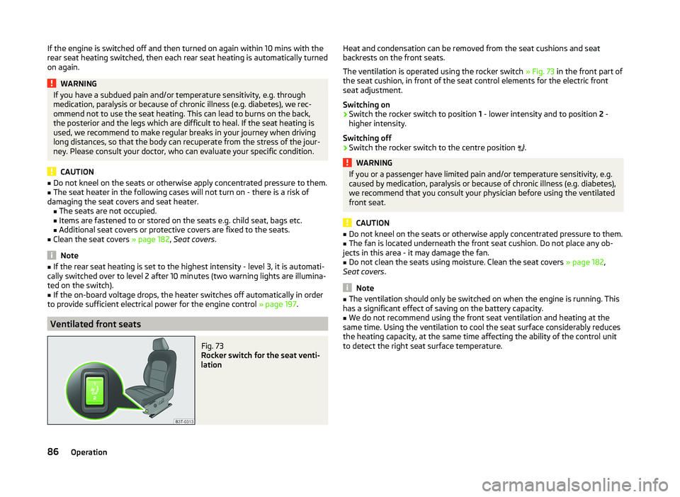
Fig. 73
Rocker switch for the seat venti-
lation
Heat and condensation can be removed from the seat cushions and seat
backrests on the front seats.
The ventilation is operated using the rocker switch » Fig. 73 in the front part of
the seat cushion, in front of the seat control elements for the electric front
seat adjustment.
Switching on›
Switch the rocker switch to position 1 - lower intensity and to position 2 -
higher intensity.
Switching off
›
Switch the rocker switch to the centre position
.
WARNINGIf you or a passenger have limited pain and/or temperature sensitivity, e.g.
caused by medication, paralysis or because of chronic illness (e.g. diabetes),
we recommend that you consult your physician before using the ventilated
front seat.
CAUTION
■ Do not kneel on the seats or otherwise apply concentrated pressure to them.■The fan is located underneath the front seat cushion. Do not place any ob-
jects in this area - it may damage the fan.■
Do not clean the seats using moisture. Clean the seat covers » page 182,
Seat covers .
Note
■
The ventilation should only be switched on when the engine is running. This
has a significant effect of saving on the battery capacity.■
We do not recommend using the front seat ventilation and heating at the
same time. Using the ventilation to cool the seat surface considerably reduces
the heating capacity, at the same time affecting the ability of the control unit
to detect the right seat surface temperature.
86Operation
Page 91 of 252
If the front seats are too far back, we recommend taking out the rear head re-
straints before the seat backrests are folded forward, to achieve a loading
space that is as horizontal as possible »
.
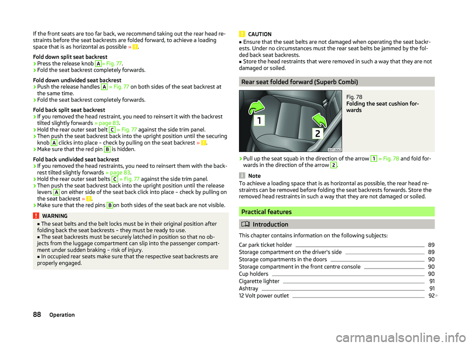
Fold down split seat backrest
›
Press the release knob
A
» Fig. 77 .
›
Fold the seat backrest completely forwards.
Fold down undivided seat backrest
›
Push the release handles
A
» Fig. 77 on both sides of the seat backrest at
the same time.
›
Fold the seat backrest completely forwards.
Fold back split seat backrest
›
If you removed the head restraint, you need to reinsert it with the backrest
tilted slightly forwards » page 83.
›
Hold the rear outer seat belt
C
» Fig. 77 against the side trim panel.
›
Then push the seat backrest back into the upright position until the securing
knob
A
clicks into place – check by pulling on the seat backrest » .
›
Make sure that the red pin
B
is hidden.
Fold back undivided seat backrest
›
If you removed the head restraints, you need to reinsert them with the back-
rest tilted slightly forwards » page 83.
›
Hold the rear outer seat belts
C
» Fig. 77 against the side trim panel.
›
Then push the seat backrest back into the upright position until the release
levers
A
on either side of the seat back click into place – check by pulling on
the seat backrest » .
›
Make sure that the red pins
B
on both sides of the seat back are not visible.
WARNING■
The seat belts and the belt locks must be in their original position after
folding back the seat backrests – they must be ready to use.■
The seat backrests must be securely latched in position so that no ob-
jects from the luggage compartment can slip into the passenger compart-
ment under sudden braking – risk of injury.
■
In occupied rear seats make sure that the respective seat backrests are
properly engaged.
CAUTION■ Ensure that the seat belts are not damaged when operating the seat backr-
ests. Under no circumstances must the rear seat belts be jammed by the fol-
ded back seat backrests.■
Store the head restraints that were removed in such a way that they are not
damaged or soiled.
Rear seat folded forward (Superb Combi)
Fig. 78
Folding the seat cushion for-
wards
›
Pull up the seat squab in the direction of the arrow
1
» Fig. 78 and fold for-
wards in the direction of the arrow
2
.
Note
To achieve a loading space that is as horizontal as possible, the rear head re-
straints can be removed before folding the seat backrests forwards. Store the
removed head restraints in such a way that they are not damaged or soiled.
Practical features
Introduction
This chapter contains information on the following subjects:
Car park ticket holder
89
Storage compartment on the driver's side
89
Storage compartments in the doors
90
Storage compartment in the front centre console
90
Cup holders
90
Cigarette lighter
91
Ashtray
91
12 Volt power outlet
92
88Operation
Page 96 of 252
Closing›Open the lid to the stop, only then can it be folded downwards and against
the direction of the arrow » Fig. 88.
The sockets marked
AUX input and the MDI input are located in the stor-
age compartment.
Note
The storage compartment is equipped with an interior light which illuminates
when the parking light is on.
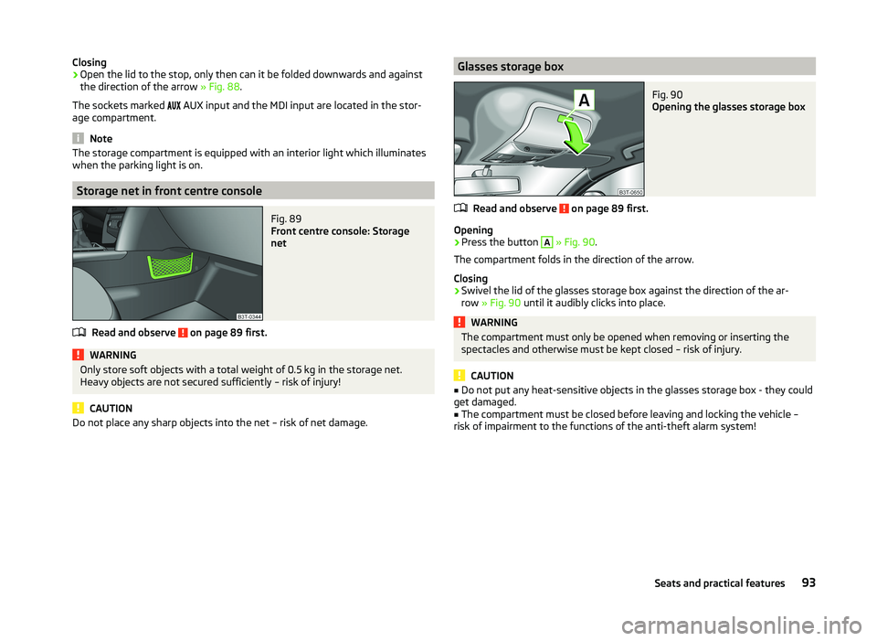
Storage net in front centre console
Fig. 89
Front centre console: Storage
net
Read and observe on page 89 first.
WARNINGOnly store soft objects with a total weight of 0.5 kg in the storage net.
Heavy objects are not secured sufficiently – risk of injury!
CAUTION
Do not place any sharp objects into the net – risk of net damage.Glasses storage boxFig. 90
Opening the glasses storage box
Read and observe on page 89 first.
Opening
›
Press the button
A
» Fig. 90 .
The compartment folds in the direction of the arrow.
Closing
›
Swivel the lid of the glasses storage box against the direction of the ar-
row » Fig. 90 until it audibly clicks into place.
WARNINGThe compartment must only be opened when removing or inserting the
spectacles and otherwise must be kept closed – risk of injury.
CAUTION
■ Do not put any heat-sensitive objects in the glasses storage box - they could
get damaged.■
The compartment must be closed before leaving and locking the vehicle –
risk of impairment to the functions of the anti-theft alarm system!
93Seats and practical features
Page 99 of 252
WARNINGThe storage compartment is not a substitute for the ashtray and must also
not be used for such purposes – risk of fire!
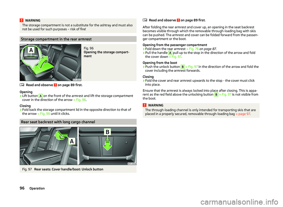
Storage compartment in the rear armrest
Fig. 96
Opening the storage compart-
ment
Read and observe on page 89 first.
Opening
›
Lift button
A
on the front of the armrest and lift the storage compartment
cover in the direction of the arrow » Fig. 96.
Closing
›
Fold back the storage compartment lid in the opposite direction to that of
the arrow » Fig. 96 until it clicks.
Rear seat backrest with long cargo channel
Fig. 97
Rear seats: Cover handle/boot: Unlock button
Read and observe on page 89 first.
After folding the rear armrest and cover up, an opening in the seat backrest
becomes visible through which the removable through-loading bag with skis
can be pushed. The armrest and cover can be folded forward from the passen-
ger compartment or the boot.
Opening from the passenger compartment
›
Fold down the rear armrest » Fig. 76 on page 87 .
›
Pull the handle
A
pull up to the stop in the direction of the arrow and fold
the cover down » Fig. 97.
Opening from the boot
›
Push the unlock button
B
» Fig. 97 in the direction of the arrow and fold the
cover including the armrest forwards.
Closing
›
Fold the cover and rear armrest upwards to the stop - the cover must click
into place.
Ensure that the armrest is always locked into place after closing. This is appa- rent as the red field above the unlocking button
B
» Fig. 97 is not visible from
the boot.
WARNINGThe through-loading channel is only intended for transporting skis that are
placed in a properly secured, removable through-loading bag » page 97.96Operation
Page 100 of 252
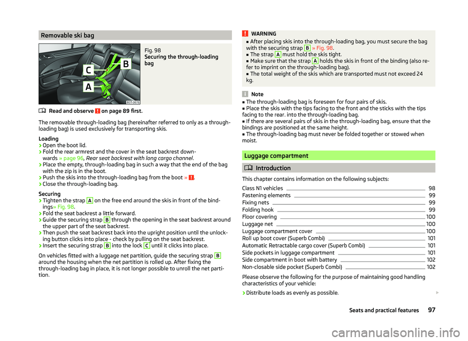
Removable ski bagFig. 98
Securing the through-loading
bag
Read and observe on page 89 first.
The removable through-loading bag (hereinafter referred to only as a through- loading bag) is used exclusively for transporting skis.
Loading
›
Open the boot lid.
›
Fold the rear armrest and the cover in the seat backrest down-
wards » page 96 , Rear seat backrest with long cargo channel .
›
Place the empty, through-loading bag in such a way that the end of the bag
with the zip is in the boot.
›
Push the skis into the through-loading bag from the boot » .
›
Close the through-loading bag.
Securing
›
Tighten the strap
A
on the free end around the skis in front of the bind-
ings » Fig. 98 .
›
Fold the seat backrest a little forward.
›
Guide the securing strap
B
through the opening in the seat backrest around
the upper part of the seat backrest.
›
Then push the seat backrest back into the upright position until the unlock-
ing button clicks into place - check by pulling on the seat backrest.
›
Insert the securing strap
B
into the lock
C
until it clicks into place.
On vehicles fitted with a luggage net partition, guide the securing strap
B
around the housing when the net partition is rolled up. After fixing the
through-loading bag in place, it is not longer possible to unroll the net parti-
tion.
WARNING■ After placing skis into the through-loading bag, you must secure the bag
with the securing strap B » Fig. 98 .■
The strap
A
must hold the skis tight.
■
Make sure that the strap
A
holds the skis in front of the binding (also re-
fer to imprint on the through-loading bag).
■
The total weight of the skis which are transported must not exceed 24
kg.
Note
■ The through-loading bag is foreseen for four pairs of skis.■Place the skis with the tips facing to the front and the sticks with the tips
facing to the rear. into the through-loading bag.■
If there are several pairs of skis in the through-loading bag, ensure that the
bindings are positioned at the same height.
■
The through-loading bag must never be folded together or stowed when
moist.
Luggage compartment
Introduction
This chapter contains information on the following subjects:
Class N1 vehicles
98
Fastening elements
99
Fixing nets
99
Folding hook
99
Floor covering
100
Luggage net
100
Luggage compartment cover
100
Roll up boot cover (Superb Combi)
101
Automatic Retractable cargo cover (Superb Combi)
101
Side pockets in luggage compartment
101
Side compartment in boot with battery
102
Non-closable side pocket (Superb Combi)
102
Please observe the following for the purpose of maintaining good handling
characteristics of your vehicle:
›
Distribute loads as evenly as possible.
97Seats and practical features
Page 102 of 252
Fastening elementsFig. 99
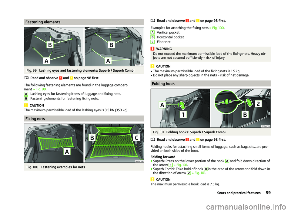
Lashing eyes and fastening elements: Superb / Superb Combi
Read and observe
and on page 98 first.
The following fastening elements are found in the luggage compart-
ment » Fig. 99 .
Lashing eyes for fastening items of luggage and fixing nets.
Fastening elements for fastening fixing nets.
CAUTION
The maximum permissible load of the lashing eyes is 3.5 kN (350 kg).
Fixing nets
Fig. 100
Fastening examples for nets
ABRead and observe and on page 98 first.
Examples for attaching the fixing nets » Fig. 100.
Vertical pocket
Horizontal pocket
Floor net
WARNINGDo not exceed the maximum permissible load of the fixing nets. Heavy ob-
jects are not secured sufficiently – risk of injury!
CAUTION
■ The maximum permissible load of the fixing nets is 1.5 kg.■Do not place any sharp objects in the nets – risk of net damage.
Folding hook
Fig. 101
Folding hooks: Superb / Superb Combi
Read and observe
and on page 98 first.
Folding hooks for attaching small items of luggage, such as bags etc., are pro-
vided on both sides of the boot.
Folding forward
›
Superb: Press on the lower portion of the hook
A
and fold down direction of
the arrow
1
» Fig. 101 .
›
Superb Combi: Take hold of hook
B
in the area of the arrow and fold down in
the direction of arrow
2
» Fig. 101 .
CAUTION
The maximum permissible hook load is 7.5 kg.ABC99Seats and practical features
Page 103 of 252
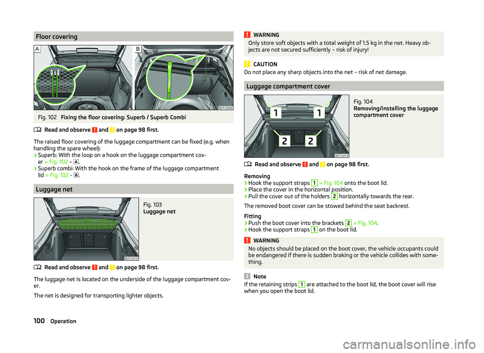
Floor coveringFig. 102
Fixing the floor covering: Superb / Superb Combi
Read and observe
and on page 98 first.
The raised floor covering of the luggage compartment can be fixed (e.g. when
handling the spare wheel):
› Superb: With the loop on a hook on the luggage compartment cov-
er » Fig. 102 –
.
› Superb combi: With the hook on the frame of the luggage compartment
lid » Fig. 102 -
.
Luggage net
Fig. 103
Luggage net
Read and observe and on page 98 first.
The luggage net is located on the underside of the luggage compartment cov-
er.
The net is designed for transporting lighter objects.
WARNINGOnly store soft objects with a total weight of 1.5 kg in the net. Heavy ob-
jects are not secured sufficiently – risk of injury!
CAUTION
Do not place any sharp objects into the net – risk of net damage.
Luggage compartment cover
Fig. 104
Removing/installing the luggage
compartment cover
Read and observe and on page 98 first.
Removing
›
Hook the support straps
1
» Fig. 104 onto the boot lid.
›
Place the cover in the horizontal position.
›
Pull the cover out of the holders
2
horizontally towards the rear.
The removed boot cover can be stowed behind the seat backrest.
Fitting
›
Push the boot cover into the brackets
2
» Fig. 104 .
›
Hook the support straps
1
on the boot lid.
WARNINGNo objects should be placed on the boot cover, the vehicle occupants could
be endangered if there is sudden braking or the vehicle collides with some-
thing.
Note
If the retaining strips 1 are attached to the boot lid, the boot cover will rise
when you open the boot lid.100Operation
Page 104 of 252
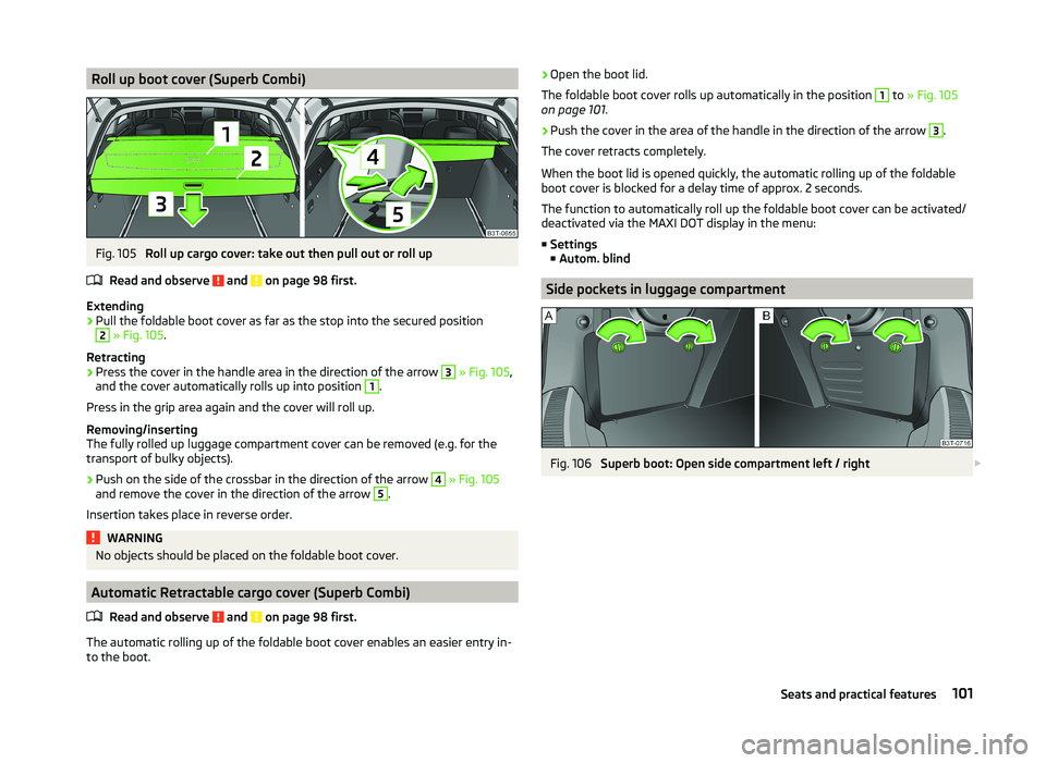
Roll up boot cover (Superb Combi)Fig. 105
Roll up cargo cover: take out then pull out or roll up
Read and observe
and on page 98 first.
Extending
›
Pull the foldable boot cover as far as the stop into the secured position
2
» Fig. 105 .
Retracting
›
Press the cover in the handle area in the direction of the arrow
3
» Fig. 105 ,
and the cover automatically rolls up into position
1
.
Press in the grip area again and the cover will roll up.
Removing/inserting
The fully rolled up luggage compartment cover can be removed (e.g. for the
transport of bulky objects).
›
Push on the side of the crossbar in the direction of the arrow
4
» Fig. 105
and remove the cover in the direction of the arrow
5
.
Insertion takes place in reverse order.
WARNINGNo objects should be placed on the foldable boot cover.
Automatic Retractable cargo cover (Superb Combi)
Read and observe
and on page 98 first.
The automatic rolling up of the foldable boot cover enables an easier entry in-
to the boot.
› Open the boot lid.
The foldable boot cover rolls up automatically in the position 1
to » Fig. 105
on page 101 .
›
Push the cover in the area of the handle in the direction of the arrow
3
.
The cover retracts completely.
When the boot lid is opened quickly, the automatic rolling up of the foldable
boot cover is blocked for a delay time of approx. 2 seconds.
The function to automatically roll up the foldable boot cover can be activated/
deactivated via the MAXI DOT display in the menu:
■ Settings
■ Autom. blind
Side pockets in luggage compartment
Fig. 106
Superb boot: Open side compartment left / right
101Seats and practical features
Page 107 of 252
›Insert the cover for the rechargeable batteries and press it down until it
clicks into place.
CAUTION
■ We recommend having faulty rechargeable batteries replaced by a ŠKODA
service partner. If the lamp is not correctly opened, it can be damaged.■
Pay attention to the correct polarity when changing the rechargeable batter-
ies.
■
The replacement rechargeable batteries must have the same specification as
the original rechargeable batteries. If other types of rechargeable batteries are
used, the power output can be reduced or it can lead to a malfunction of the
lamp.
For the sake of the environment
Dispose of used rechargeable batteries in accordance with national legal provi- sions.
Variable loading floor in the luggage compartment (Estate)
Introduction
This chapter contains information on the following subjects:
Dividing the luggage compartment
104
Remove variable loading floor
104
The variable loading floor makes handling of bulky items of luggage easier.
CAUTION
The maximum permissible load of the variable loading floor is 75 kg.
Note
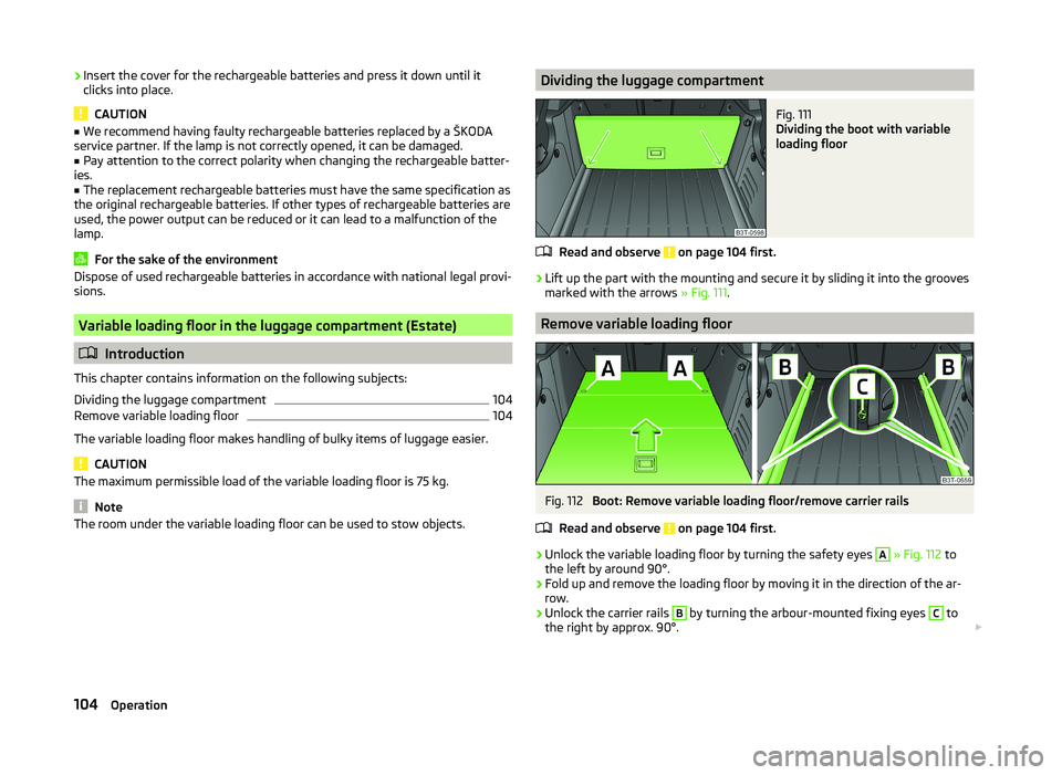
The room under the variable loading floor can be used to stow objects.Dividing the luggage compartmentFig. 111
Dividing the boot with variable
loading floor
Read and observe on page 104 first.
›
Lift up the part with the mounting and secure it by sliding it into the grooves
marked with the arrows » Fig. 111.
Remove variable loading floor
Fig. 112
Boot: Remove variable loading floor/remove carrier rails
Read and observe
on page 104 first.
›
Unlock the variable loading floor by turning the safety eyes
A
» Fig. 112 to
the left by around 90°.
›
Fold up and remove the loading floor by moving it in the direction of the ar-
row.
›
Unlock the carrier rails
B
by turning the arbour-mounted fixing eyes
C
to
the right by approx. 90°.
104Operation
Page 108 of 252
WARNINGEnsure that the carrier rails and variable loading floor are correctly fastened
when installing the variable loading floor. If this is not the case, there is a
risk of injury for the occupants.
Extending variable loading floor with integrated aluminium rails
and fastening elements (Superb Combi)
Introduction
This chapter contains information on the following subjects:
Partial extension of variable load floor
105
Divide boot
105
Fit and remove variable loading floor
106
Fixing set
106
Movable lashing eyes
107
The variable loading floor makes handling of bulky items of luggage easier.
CAUTION
The maximum permissible load of the variable loading floor is 75 kg.
Note
The space below the variable loading floor can be used for stowing objects, for
example the fastening elements, removed foldable boot cover, etc.
Partial extension of variable load floor
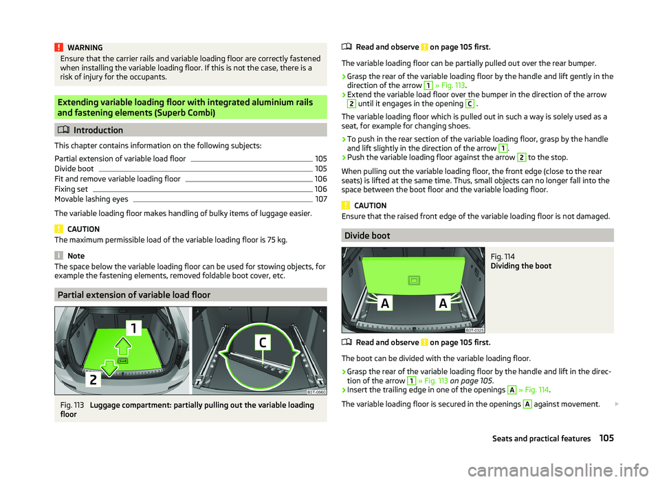
Fig. 113
Luggage compartment: partially pulling out the variable loading
floor
Read and observe on page 105 first.
The variable loading floor can be partially pulled out over the rear bumper.
›
Grasp the rear of the variable loading floor by the handle and lift gently in the
direction of the arrow
1
» Fig. 113 .
›
Extend the variable load floor over the bumper in the direction of the arrow
2
until it engages in the opening
C
.
The variable loading floor which is pulled out in such a way is solely used as a
seat, for example for changing shoes.
›
To push in the rear section of the variable loading floor, grasp by the handle
and lift slightly in the direction of the arrow
1
.
›
Push the variable loading floor against the arrow
2
to the stop.
When pulling out the variable loading floor, the front edge (close to the rear
seats) is lifted at the same time. Thus, small objects can no longer fall into the
space between the boot floor and the variable loading floor.
CAUTION
Ensure that the raised front edge of the variable loading floor is not damaged.
Divide boot
Fig. 114
Dividing the boot
Read and observe on page 105 first.
The boot can be divided with the variable loading floor.
›
Grasp the rear of the variable loading floor by the handle and lift in the direc-
tion of the arrow
1
» Fig. 113 on page 105 .
›
Insert the trailing edge in one of the openings
A
» Fig. 114 .
The variable loading floor is secured in the openings
A
against movement.
105Seats and practical features