engine SKODA SUPERB 2013 2.G / (B6/3T) Owner's Guide
[x] Cancel search | Manufacturer: SKODA, Model Year: 2013, Model line: SUPERB, Model: SKODA SUPERB 2013 2.G / (B6/3T)Pages: 274, PDF Size: 17.31 MB
Page 73 of 274
›Switch on the ignition.›Turn dial for the exterior mirror control into position
» page 65 .›
Engage reverse gear.
›
Adjust the front passenger's mirror to the desired position » page 65.
›
Disengage reverse gear.
The adjusted position of the exterior mirror is stored in the remote control key
memory.
Enable automatic storage
›
Unlock the vehicle with the remote control key.
›
Press and hold any memory button
B
» Fig. 53 on page 69. After the seat has
assumed the position stored under this button, at the same time press the but-
ton
on the remote control key within 10 seconds.
The successful activation of the automatic storage function for each key is con-
firmed by an acoustic signal.
The seat and external mirror positions which are already saved in the memory
button are not saved in the memory of the key.
The seat can be adjusted to the required position if necessary » page 67.
After locking the vehicle, the current positions of the driver's seat and the exter-
nal mirrors are saved in the memory of the remote control key.
Disable the function of automatic storage
›
Unlock the vehicle with the remote control key.
›
Press and hold the SET button
A
» Fig. 53 on page 69. At the same time, press
the button on the remote control key within 10 seconds.
The successful deactivation of the automatic storage function for each key is con-
firmed by an acoustic signal.
Stopping the ongoing adjustment
›
Press any button on the driver's seat or the button on the remote control
key.
Seat features
Introduction
This chapter contains information on the following subjects:
Seat heaters
70
Ventilated front seats
71
Convenience features of passenger seat
72
Armrest, front
72
Armrest rear
73
Seat backrests
73
Rear seat folded forward (Superb Combi)
74
Seat heaters
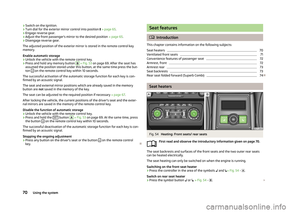
Fig. 54
Heating: Front seats/ rear seats
First read and observe the introductory information given on page 70.
The seat backrests and surfaces of the front seats and the two outer rear seats
can be heated electrically.
The seat heating can only be switched on when the engine is running.
Switching on the front seat heater
›
Press the controller in the area of the symbols
and
» Fig. 54 -
.
Switch on rear seat heater
›
Press the symbol button
or
» Fig. 54 -
.
70Using the system
Page 74 of 274
By pressing the button once, the heating is switched to the highest intensity -level 3, which is indicated by all three of the indicator lights in the switch lightingup.
With repeated pressing of the switch, the heating is turned down until it goes off. The seat heating level is indicated by the number of illuminated warning lights inthe respective control.WARNINGIf you have a subdued pain and/or temperature sensitivity, e.g. through medi-
cation, paralysis or because of chronic illness (e.g. diabetes), we recommend
not to use the seat heating. This can lead to burns on the back, the posterior
and the legs which are difficult to heal. If the seat heating is used, we recom-
mend to make regular breaks in your journey when driving long distances, so
that the body can recuperate from the stress of the journey. Please consult
your doctor, who can evaluate your specific condition.
CAUTION
■ Do not kneel on the seats or otherwise apply concentrated pressure to them.■Do not turn on the seat heater if seats are not occupied.■
Do not switch on the seat heating if the seats have objects attached to or
placed on them, for example a child seat, a bag, etc. A fault of the heating ele-
ments in the seat heating can occur.
■
If additional seat covers or protective covers are attached to the seats, do not
turn on the seat heater - there is a risk of damaging the seat covers and seat
heating.
■
Do not clean the seats using moisture » page 203, Seat covers .
Note
■
If the on-board voltage drops, the seat heating is switched off automatically, in
order to provide sufficient electrical energy for the engine control » page 218.■
If the heaters for the rear seats are set to the highest intensity - level 3, they
are automatically switched over to level 2 after 10 minutes (two indicator lights
are illuminated on the switch).
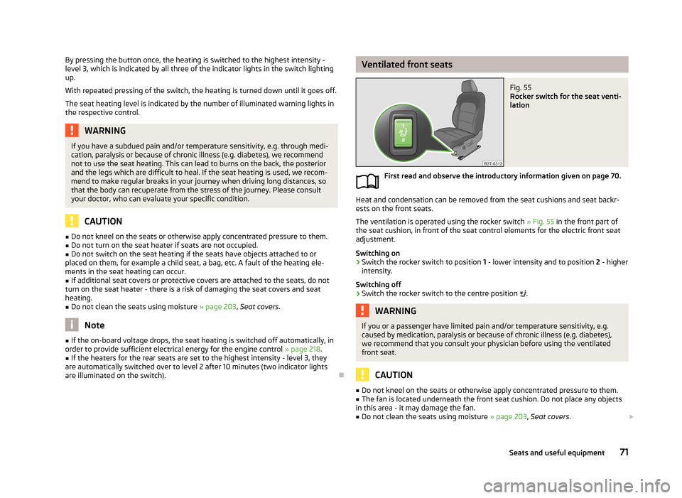
Ventilated front seatsFig. 55
Rocker switch for the seat venti-
lation
First read and observe the introductory information given on page 70.
Heat and condensation can be removed from the seat cushions and seat backr- ests on the front seats.
The ventilation is operated using the rocker switch » Fig. 55 in the front part of
the seat cushion, in front of the seat control elements for the electric front seat
adjustment.
Switching on
›
Switch the rocker switch to position 1 - lower intensity and to position 2 - higher
intensity.
Switching off
›
Switch the rocker switch to the centre position
.
WARNINGIf you or a passenger have limited pain and/or temperature sensitivity, e.g.
caused by medication, paralysis or because of chronic illness (e.g. diabetes),
we recommend that you consult your physician before using the ventilated
front seat.
CAUTION
■ Do not kneel on the seats or otherwise apply concentrated pressure to them.■The fan is located underneath the front seat cushion. Do not place any objects
in this area - it may damage the fan.■
Do not clean the seats using moisture » page 203, Seat covers .
71Seats and useful equipment
Page 75 of 274
Note■The ventilation should only be switched on when the engine is running. This
has a significant effect of saving on the battery capacity.■
We do not recommend using the front seat ventilation and heating at the same
time. Using the ventilation to cool the seat surface considerably reduces the
heating capacity, at the same time affecting the ability of the control unit to de-
tect the right seat surface temperature.
Convenience features of passenger seat
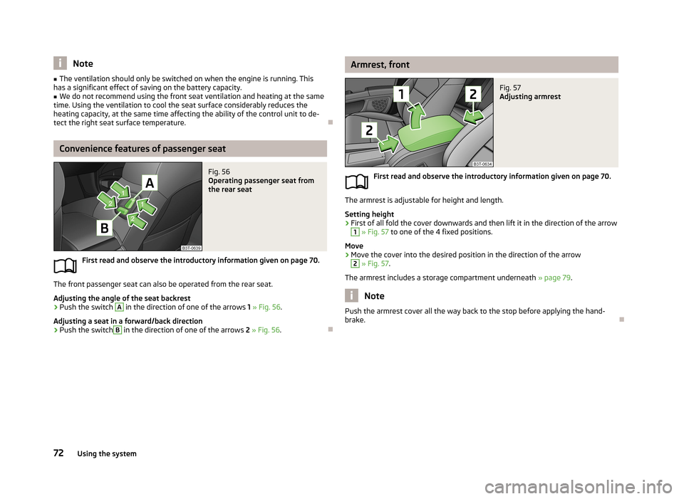
Fig. 56
Operating passenger seat from
the rear seat
First read and observe the introductory information given on page 70.
The front passenger seat can also be operated from the rear seat.
Adjusting the angle of the seat backrest
›
Push the switch
A
in the direction of one of the arrows 1 » Fig. 56 .
Adjusting a seat in a forward/back direction
›
Push the switch
B
in the direction of one of the arrows 2 » Fig. 56 .
Armrest, frontFig. 57
Adjusting armrest
First read and observe the introductory information given on page 70.
The armrest is adjustable for height and length.
Setting height
›
First of all fold the cover downwards and then lift it in the direction of the arrow
1
» Fig. 57 to one of the 4 fixed positions.
Move
›
Move the cover into the desired position in the direction of the arrow
2
» Fig. 57 .
The armrest includes a storage compartment underneath » page 79.
Note
Push the armrest cover all the way back to the stop before applying the hand-
brake.
72Using the system
Page 81 of 274
›Grasp the ashtray insert B
» Fig. 68 in the area marked with the arrows and
remove it in the direction of the arrow 2.
Insertion takes place in the reverse order.WARNINGNever place flammable objects in the ashtray – risk of fire!
Note
The ashtrays are fitted with an interior light which lights up when the parking
light is on.
12-Volt power outlet
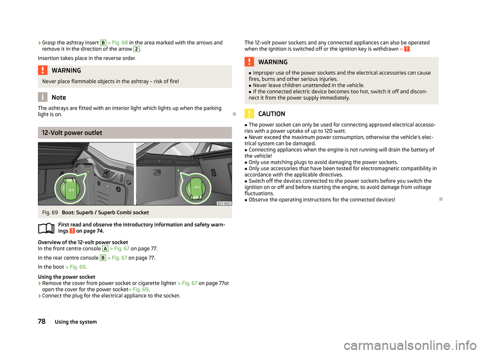
Fig. 69
Boot: Superb / Superb Combi socket
First read and observe the introductory information and safety warn- ings
on page 74.
Overview of the 12-volt power socket
In the front centre console
A
» Fig. 67 on page 77.
In the rear centre console
B
» Fig. 67 on page 77.
In the boot » Fig. 69.
Using the power socket
›
Remove the cover from power socket or cigarette lighter » Fig. 67 on page 77or
open the cover for the power socket » Fig. 69.
›
Connect the plug for the electrical appliance to the socket.
The 12-volt power sockets and any connected appliances can also be operated
when the ignition is switched off or the ignition key is withdrawn » .WARNING■
Improper use of the power sockets and the electrical accessories can cause
fires, burns and other serious injuries.■
Never leave children unattended in the vehicle.
■
If the connected electric device becomes too hot, switch it off and discon-
nect it from the power supply immediately.
CAUTION
■ The power socket can only be used for connecting approved electrical accesso-
ries with a power uptake of up to 120 watt.■
Never exceed the maximum power consumption, otherwise the vehicle's elec-
trical system can be damaged.
■
Connecting appliances when the engine is not running will drain the battery of
the vehicle!
■
Only use matching plugs to avoid damaging the power sockets.
■
Only use accessories that have been tested for electromagnetic compatibility in
accordance with the applicable directives.
■
Switch off the devices connected to the power sockets before you switch the
ignition on or off and before starting the engine, to avoid damage from voltage
fluctuations.
■
Observe the operating instructions for the connected devices!
78Using the system
Page 94 of 274

The lamp is supplied by three rechargeable type AAA batteries. The rechargeable
batteries are constantly charged when the engine is running. It takes approx. 3
hours to fully charge the rechargeable batteries.
The lamp is fitted with magnets. Therefore it is possible to attach the lamp, forexample on the vehicle body, after removing it.
CAUTION
The removable lamp is not watertight and must therefore be protected against
moisture.
Note
■ If the lamp is not correctly inserted into the holder, it does not light up when
the boot lid is opened and the rechargeable batteries are not charged.■
If the lamp is not switched off and it is correctly inserted in the holder, the bulbs
in the front part
C
» Fig. 92 on page 91 of the lamp are automatically switched
off.
Use light
Fig. 92
Use light / remove light
First read and observe the introductory information and safety warn-
ings
on page 90.
Use light
›
If you press button
A
» Fig. 92 once, the lamp lights up with 100 % light inten-
sity.
›
If you press button
A
again, the lamp lights up with 50 % light intensity.
›
Press
A
button once again - the light goes out.
Remove the lamp from the holder›Grasp the lamp in the areas of the arrows D » Fig. 92 and swivel it in the direc-
tion of the arrow E
.
Reinserting the lamp the holder
›
First of all place the deactivated lamp in the holder on the side facing the boot lid and then press on the lamp from the other side until it is clicks into place.
Changing rechargeable light batteries
First read and observe the introductory information and safety warn-ings
on page 90.
Proceed as follows if you wish to replace the faulty rechargeable batteries your-
self:
›
Remove the lamp.
›
Lever off the cover for the rechargeable batteries with a narrow and pointed object from the location of the lock-off clips
F
» Fig. 92 on page 91.
›
Remove the faulty rechargeable batteries from the lamp.
›
Insert the new rechargeable batteries.
›
Insert the cover for the rechargeable batteries and press it down until it clicks
into place.
CAUTION
We recommend having faulty rechargeable batteries replaced by a ŠKODA service
partner. If the lamp is not correctly opened, it can be damaged.
For the sake of the environment
Dispose of used rechargeable batteries in accordance with national legal provi-
sions.
Note
■ Pay attention to the correct polarity when changing the rechargeable batteries.■The replacement rechargeable batteries must have the same specification as
the original rechargeable batteries. If other types of rechargeable batteries are
used, the power output can be reduced or it can lead to a malfunction of the
lamp.
91Seats and useful equipment
Page 101 of 274
Air conditioning system
Heating, ventilation and cooling
Introduction
This chapter contains information on the following subjects:
Air outlets
99
Using the air conditioning system economically
99
Operational problems
100
The heating effect is dependent upon the coolant temperature, thus full heat
output only occurs when the engine has reached its operating temperature.
If the cooling system is switched on, the temperature and air humidity drops in
the vehicle. The cooling system prevents the windows from misting up during
winter months.
It is possible to briefly activate recirculated air mode to enhance the cooling ef-
fect.
Please refer to the information regarding recirculated air mode for the air-condi-
tioning system » page 102 or for Climatronic » page 105.
WARNINGFor your own safety and that of other road users, ensure that all the windows
are free of ice, snow and misting. Please familiarize yourself about how to cor- rectly operate the heating and ventilation systems, how to demist and defrost
the windows, as well as with the cooling mode.
CAUTION
■ The air inlet in front of the windscreen must be free (e.g. of ice, snow or leaves)
to ensure that the heating and cooling system operates properly.■
After switching on the cooling Condensation from the evaporator of the air con-
ditioning may drip down and form a puddle below the vehicle. This is not a leak!
Note■ The used air streams out through the vents in the boot.■We recommend that you do not smoke in the vehicle when the recirculating air
mode is operating since the smoke which is drawn at the evaporator from the in- terior of the vehicle forms deposits in the evaporator of the air conditioning sys-tem. This produces a permanent odour when the air conditioning system is oper-ating which can only be eliminated through considerable effort and expense (re-
placement of compressor).
98Using the system
Page 102 of 274
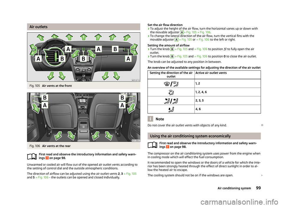
Air outletsFig. 105
Air vents at the front
Fig. 106
Air vents at the rear
First read and observe the introductory information and safety warn-
ings
on page 98.
Unwarmed or cooled air will flow out of the opened air outlet vents according to
the setting of control dial and the outside atmospheric conditions.
The direction of airflow can be adjusted using the air outlet vents 2, 3 » Fig. 105
and 5 » Fig. 106 - the outlets can be opened and closed individually.
Set the air flow direction›To adjust the height of the air flow, turn the horizontal vanes up or down with
the movable adjuster A
» Fig. 105 » Fig. 106 .
›
To change the lateral direction of the air flow, turn the vertical fins with the
movable adjuster
A
» Fig. 105 or » Fig. 106 to the left or right.
Setting the amount of airflow
›
Turn the knob
B
» Fig. 105 and » Fig. 106 to position to fully open the air
outlet.
›
Turn the knob
B
» Fig. 105 and » Fig. 106 to position 0 to close the air outlet.
The knob can be adjusted to any position in between.
An overview of the available settings for adjusting the direction of the air outlet
Setting the direction of the air outletActive air outlet vents1, 21, 2, 4, 6 2, 3, 54, 6
Note
Do not cover the air outlet vents with objects of any kind.
Using the air conditioning system economically
First read and observe the introductory information and safety warn-ings
on page 98.
The compressor on the air conditioning system uses power from the engine whenin cooling mode which will effect the fuel consumption.
It recommended to open the windows or the doors of a vehicle for which the inte- rior has been strongly heated through the effect of direct sunlight in order to al-low the heated air to escape.
The cooling system should not be on if the windows are open.
99Air conditioning system
Page 103 of 274
For the sake of the environmentPollutant emissions are also lower when fuel is being saved » page 143, Eco-
nomical driving and environmental sustainability .
Operational problems
First read and observe the introductory information and safety warn-
ings
on page 98.
If the cooling system does not operate at outside temperatures higher than +5 °C,
there is a problem in the system. The reasons for this may be.
› One of the fuses has blown. Check the fuse and replace if necessa-
ry » page 244 .
› The cooling system has switched off automatically for a short time because the
coolant temperature of the engine is too hot » page 11.
If you are not able to resolve the operational problem yourself, or if the cooler output has reduced, switch off the cooling system and seek assistance from a
specialist garage.
Air conditioning system (manual air conditioning
system)
Introduction
This chapter contains information on the following subjects: Control elements
100
adjusting
102
Recirculated air mode
102
The cooling system operates only if the following conditions are met. The cooling system is switched on » page 100.
The engine is running.
The outside temperature is above approx. +2 °C.
The blower switch is switched on (positions 1-4).
Under certain circumstances, air at a temperature of about 5 °C can flow out of the vents when the cooling system is switched on.
If the desired interior temperature can also be achieved without activating the
cooling system, fresh air mode should be selected.
The cooling system is switched off at a high coolant temperature in order to pro-
vide cooling at a high load of the engine.
CAUTION
Lengthy and uneven distribution of the air flow out of the vents (especially
around the feet) and large differences in temperature, for example, when getting
out of the vehicle, can cause susceptible individuals to catch a cold.
Note
We recommend that you have the air conditioning system cleaned by a specialist
garage once every year.
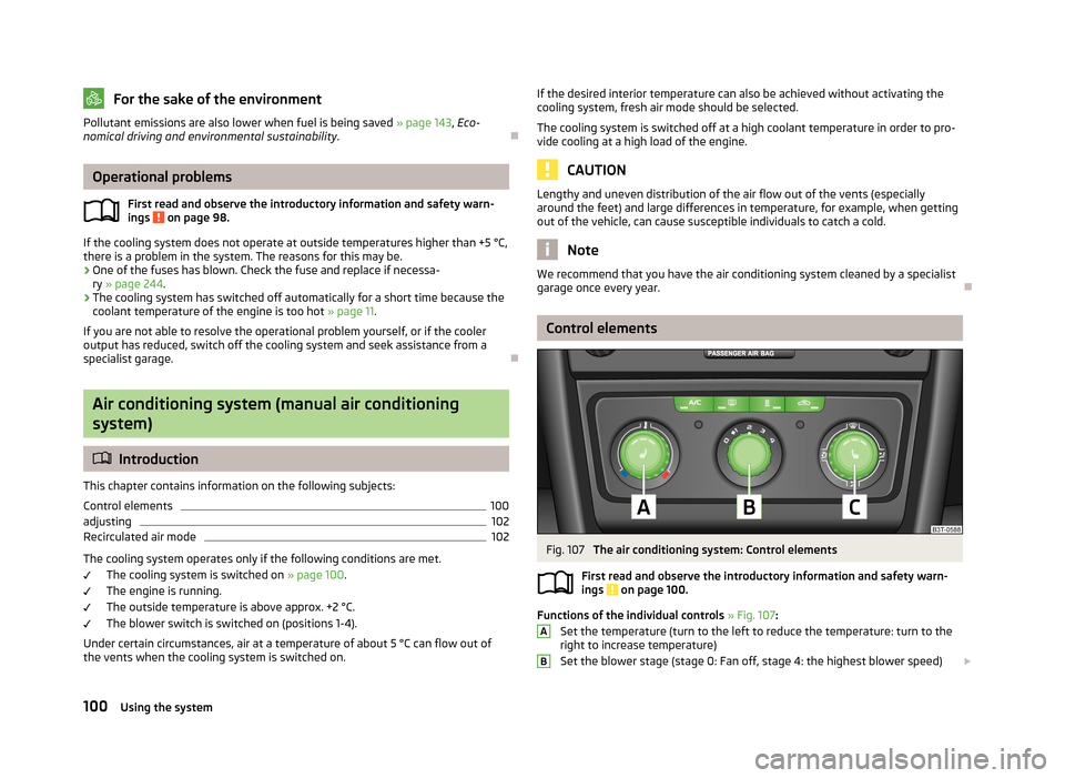
Control elements
Fig. 107
The air conditioning system: Control elements
First read and observe the introductory information and safety warn- ings
on page 100.
Functions of the individual controls » Fig. 107 :
Set the temperature (turn to the left to reduce the temperature: turn to the right to increase temperature)
Set the blower stage (stage 0: Fan off, stage 4: the highest blower speed)
AB100Using the system
Page 106 of 274
Climatronic (automatic air conditioning system)
Introduction
This chapter contains information on the following subjects:
Control elements
103
automatic mode
104
Switching the cooling system on/off
104
Setting the temperature
104
Recirculation mode - Version 1
105
Recirculation mode - Version 2
106
Controlling blower
106
Defrosting windscreen
106
The Climatronic in automatic mode ensures the best-possible setting of the tem-
perature of the outflowing air, the blower stage and air distribution.
The system also takes sunlight into account, which eliminates the need to alterthe settings manually.
The cooling system operates only if the following conditions are met. The cooling system is switched on » page 100.
The engine is running.
The outside temperature is above approx. +2 °C.
The cooling system is switched off at a high coolant temperature in order to pro-
vide cooling at a high load of the engine.
Aeration of the vehicle when ignition is switched off
On models fitted with power sliding/tilting roof with sollar cells, the fresh air blower is automatically switched over to “solar mode” if the sun ray's are suffi-
cient after switching off the ignition. The solar cells on the sliding/tilting roof de-
liver power for the fresh air blower. This supplies the interior of the car with fresh air.
For an optimum ventilation, the air outlet vents 2 and 3 must be opened » Fig. 105
on page 99.
The ventilation functions only when the sliding/tilting roof is fully closed.
Note■ We recommend that you have Climatronic cleaned by a specialist garage once
every year.■
On vehicles equipped with a factory-fitted radio or radio navigation system, the
Climatronic information is also shown on their displays. This function can be
switched off, see » operating instructions for the radio or navigation system .
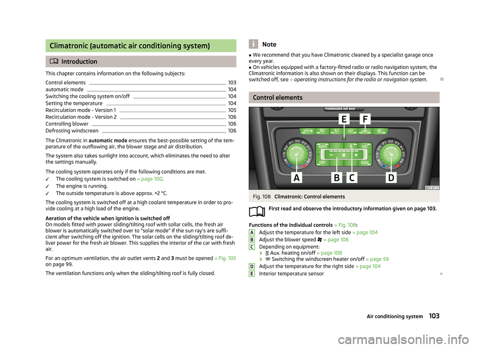
Control elements
Fig. 108
Climatronic: Control elements
First read and observe the introductory information given on page 103.
Functions of the individual controls » Fig. 108 :
Adjust the temperature for the left side » page 104
Adjust the blower speed
» page 106
Depending on equipment:
›
Aux. heating on/off » page 108
›
Switching the windscreen heater on/off » page 59
Adjust the temperature for the right side » page 104
Interior temperature sensor
ABCDE103Air conditioning system
Page 110 of 274
Auxiliary heating (auxiliary heating and ventilation)
Introduction
This chapter contains information on the following subjects:
Switching on/off
108
Radio remote control
109
Conditions for the functioning of auxiliary heating (Aux. heating and ventilation),
hereinafter referred to only as auxiliary heating (Aux. heating).
The charge state of the vehicle battery is sufficient.
The fuel supply is adequate (the warning icon
is not lit in the display of the
instrument cluster).
Auxiliary ventilation
The auxiliary ventilation enables fresh air to flow into the vehicle interior by
switching off the engine, whereby the interior temperature is effectively de-
creased (e.g. with the vehicle parked in the sun).
Auxiliary heating (aux. heating)
The auxiliary heating (aux. heating) can be used when stationary, when the en- gine is switched off to preheat the vehicle and while driving (e.g. during the heat-
ing phase of the engine).
The auxiliary heating (auxiliary heating) functions in connection with the air-con-
ditioning system or Climatronic.
The auxiliary heating (aux. heating) also warms up the engine. This is not valid for
vehicles with the 3.6 l/191 kW FSI engine.
The auxiliary heating (parking heating) warms up the coolant by combusting fuel
from the vehicle tank. The coolant heats air flowing into the passenger compart-
ment (as long as the blower fan speed
B
» Fig. 107 on page 100 or » Fig. 108 on
page 103 is not set to zero).
WARNING■ The auxiliary heating (aux. heating) must never be operated in closed rooms
(e.g. garages) – risk of poisoning!■
The auxiliary heating (aux. heating) must not be allowed to run during refu-
elling – risk of fire.
■
The exhaust pipe of the auxiliary heating (aux. heating) is located on the un-
derside of the vehicle. Therefore, if you wish to operate the auxiliary heating
(aux. heating), do not park the vehicle in such a way that the exhaust gases
can come into contact with highly flammable materials (e.g. dry grass) or easily
inflammable substances (e.g. spilt fuel) – risk of fire.
CAUTION
■ Running auxiliary heating (aux. heating) consumes fuel from the vehicle tank
and automatically controls the filling level. If only a low quantity of fuel is present in the fuel tank, the auxiliary heating (aux. heating) switches off.■
The exhaust pipe of the auxiliary heating (aux. heating), which is located on the
underside of the vehicle, must not be clogged and the exhaust flow must not be blocked.
■
If the auxiliary heating (aux. heating) is running, the vehicle battery discharges.
If the auxiliary heating and ventilation has been operated several times over a
longer period, the vehicle must be driven a few kilometres in order to recharge
the vehicle battery.
Note
■ The auxiliary heating (aux. heating) switches on the blower B » Fig. 107 on
page 100 or » Fig. 108 on page 103 only if it has achieved a coolant temperature
of approx. 50 °C.■
At low outside temperatures, this can result in a formation of water vapour in
the area of the engine compartment. This is quite normal and is not an operating problem.
■
The air inlet in front of the windscreen must be free (e.g. of ice, snow or leaves)
to ensure that the auxiliary heating (aux. heating) operates properly.
■
So that warm air can flow into the vehicle interior after switching on the auxili-
ary heating, you must maintain the comfort temperature normally selected by
you, leave the fan switched on and leave the air outlet vents in an open position.
It is recommended to put the air flow in the position or .
107Air conditioning system