fuses SKODA SUPERB 2013 2.G / (B6/3T) Owner's Manual
[x] Cancel search | Manufacturer: SKODA, Model Year: 2013, Model line: SUPERB, Model: SKODA SUPERB 2013 2.G / (B6/3T)Pages: 274, PDF Size: 17.31 MB
Page 7 of 274
General Maintenance
Car care191
Service intervals
191
Services, modifications, and technical
alterations
193
Washing your car
196
Taking care of your vehicle exterior
198
Taking care of the interior
201
Inspecting and replenishing
204
Fuel
204
Engine compartment
206
Engine oil
210
Coolant
212
Brake fluid
214
Vehicle battery
215
Wheels
220
Tyres and wheel rims
220
Winter operation
226
Do-it-yourself
Emergency equipment and self-help
227
Emergency equipment
227
Changing a wheel
229
Tyre repair
232
Jump-starting
234
Towing the vehicle
236
Radio remote control
238
Emergency unlocking/locking
240
Emergency operation of the sliding/tilting roof
241
Replacing windscreen wiper blades
242
Fuses and light bulbs
244
Fuses
244
Bulbs
247Technical data
Technical data252
Vehicle data
252
Index
4Table of Contents
Page 19 of 274
GeneratorFirst read and observe the introductory information and safety warn-ings
on page 14.
If the indicator light lights up when the engine is running, the vehicle battery is
not being charged.
Seek help from a specialist garage. The electrical system requires checking.
WARNINGIf you have to stop for technical reasons, then park the vehicle at a safe dis-
tance from the traffic, switch off the engine and activate the hazard warning
light system » page 56, Hazard warning light system .
CAUTION
If the warning light (cooling system fault) lights up in addition to the warn-
ing light while driving, do not continue to drive! Stop the engine - there is a
risk of engine damage!
Open door
First read and observe the introductory information and safety warn-ings
on page 14.
The indicator light
comes on, if one or several doors are opened.
WARNINGIf you have to stop for technical reasons, then park the vehicle at a safe dis-
tance from the traffic, switch off the engine and activate the hazard warning
light system » page 56.
Engine oil pressure
First read and observe the introductory information and safety warn-
ings
on page 14.
When the indicator light is flashing , the engine oil pressure is too low.
The following message is shown in the MAXI DOT display.
Oil pressure: Log book!
Stop the vehicle, switch off the engine, and check the level of the engine
oil » page 211 .
Even if the oil level is correct, do not drive any further if the indicator light is
flashing . Also do not leave the engine running at an idling speed.
Seek help from a specialist garage.WARNINGIf you have to stop for technical reasons, then park the vehicle at a safe dis-
tance from the traffic, switch off the engine and activate the hazard warning
light system » page 56.
Coolant
First read and observe the introductory information and safety warn-ings
on page 14.
If the indicator light
lights up or flashes, either the coolant temperature is too
high or the coolant level is too low.
The following message is shown in the MAXI DOT display. Check coolant! Log book!
Stop the vehicle, switch off the engine, check the level of the coolant » page 213,
and refill the coolant if necessary » page 214.
If the coolant is within the specified range, the increased temperature may be caused by an operating problem at the radiator fan. Check the fuse for the radia-
tor fan, replace if necessary » page 246, Fuses in the engine compartment .
Do not continue driving if the warning light
is lit, even though the coolant level
is correct and the fuse for the fan is in working order
!
Seek help from a specialist garage.
16Using the system
Page 103 of 274
For the sake of the environmentPollutant emissions are also lower when fuel is being saved » page 143, Eco-
nomical driving and environmental sustainability .
Operational problems
First read and observe the introductory information and safety warn-
ings
on page 98.
If the cooling system does not operate at outside temperatures higher than +5 °C,
there is a problem in the system. The reasons for this may be.
› One of the fuses has blown. Check the fuse and replace if necessa-
ry » page 244 .
› The cooling system has switched off automatically for a short time because the
coolant temperature of the engine is too hot » page 11.
If you are not able to resolve the operational problem yourself, or if the cooler output has reduced, switch off the cooling system and seek assistance from a
specialist garage.
Air conditioning system (manual air conditioning
system)
Introduction
This chapter contains information on the following subjects: Control elements
100
adjusting
102
Recirculated air mode
102
The cooling system operates only if the following conditions are met. The cooling system is switched on » page 100.
The engine is running.
The outside temperature is above approx. +2 °C.
The blower switch is switched on (positions 1-4).
Under certain circumstances, air at a temperature of about 5 °C can flow out of the vents when the cooling system is switched on.
If the desired interior temperature can also be achieved without activating the
cooling system, fresh air mode should be selected.
The cooling system is switched off at a high coolant temperature in order to pro-
vide cooling at a high load of the engine.
CAUTION
Lengthy and uneven distribution of the air flow out of the vents (especially
around the feet) and large differences in temperature, for example, when getting
out of the vehicle, can cause susceptible individuals to catch a cold.
Note
We recommend that you have the air conditioning system cleaned by a specialist
garage once every year.
Control elements
Fig. 107
The air conditioning system: Control elements
First read and observe the introductory information and safety warn- ings
on page 100.
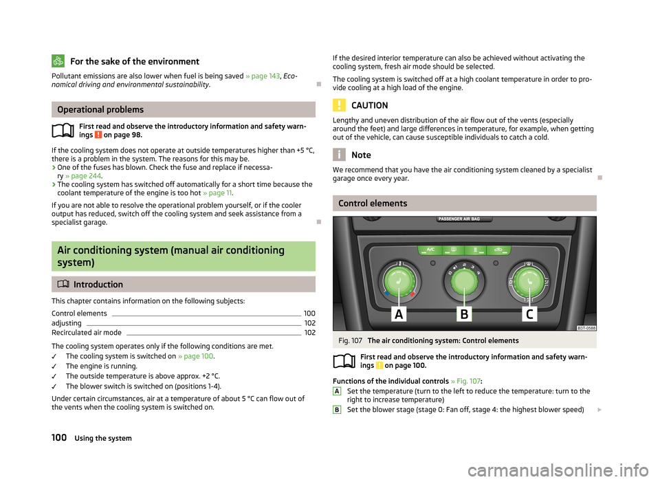
Functions of the individual controls » Fig. 107 :
Set the temperature (turn to the left to reduce the temperature: turn to the right to increase temperature)
Set the blower stage (stage 0: Fan off, stage 4: the highest blower speed)
AB100Using the system
Page 136 of 274
›Depress and hold the clutch pedal (vehicles with a manual gearbox) or brake
pedal (vehicles with an automatic gearbox) until the engine starts.›
Turn the key into position
3
to the stop and release immediately after the en-
gine has been started – do not apply the accelerator.
After letting go, the vehicle key will return to position
2
.
If the engine does not start within 10 seconds, turn the key to position
1
. Repeat
the start-up process after approx. half a minute.
›
Release the handbrake.
Vehicles with manual transmission
The engine will not start if the clutch pedal is not depressed.
The following message is shown in the information cluster display.
Depress clutch to start.CLUTCH
Vehicles with automatic transmission
The engine will not start if the brake pedal is not depressed.
The warning light
lights up in the instrument cluster and the following mes-
sage appears in the display.
Apply the brake to start.
BRAKE
CAUTION
■ If the engine does not start up after a second attempt, one of the following
fuses may be defective. ■Petrol engine - fuse for the electric fuel pump.
■ Diesel engine - fuse for the control unit for glow plugs or glow plug relay and
fuel pump.■
Check the fuse and replace if necessary » page 244, or seek assistance from a
specialist garage.
Stopping the engine
First read and observe the introductory information and safety warn-ings
on page 131.
Switch off the engine by turning the ignition key into position
1
» Fig. 118 on
page 132.
For vehicles with automatic transmission, the ignition key can only be removed if
the selector lever is in position P.
Starting and stopping the engine - KESSY
Introduction
This chapter contains information on the following subjects:
Steering lock / unlock
134
Switching on the ignition
135
Starting the engine
135
Switching off the ignition
136
Switching off the engine
136
Emergency start-up of the engine
136
Emergency ignition shutoff system
136
The KESSY system (Keyless Entry Exit System, hereinafter referred to only as sys- tem) allows the switching on or switching off of the ignition and starting or stop-ping of the engine without the active use of the key.
A key must be in the vehicle to unlock the steering, switch on the ignition and
start the vehicle. When travelling the key must be in the vehicle.
The engine running noises may louder at first be louder for a short time afterstarting the cold engine. This is quite normal and is not an operating problem.
WARNING■ Never leave the key in the vehicle when you exit the vehicle. This is particu-
larly important if children are left in the vehicle. Children could otherwise start
the engine for example – risk of accident or injury!■
Never leave the vehicle unattended with the engine running.
■
Never switch off the engine before the vehicle is stationary – risk of acci-
dent!
133Starting-off and Driving
Page 138 of 274

If the system does not unlock the steering at the first time (for example when the
front wheels are in contact with an obstacle), then two more unlocking attempts
are performed automatically.
If the steering is still not unlocked, then the following message is displayed on
the display of the instrument cluster.
Move the steering wheel!
MOVE STEERING WHEEL
Slightly move the steering wheel and the system will make up to 3 more attempts
to unlock after 2 seconds. At the same time, the indicator light flashes.
If the steering is still not unlocked, to try to eliminate the possible cause and then
repeat the unlocking attempt.
Switching on the ignition
First read and observe the introductory information and safety warn-
ings
on page 133.
›
Press the starter button » Fig. 119 on page 134 briefly.
The ignition is switched on.
Note
The ignition is switched on when indicated by the lighting up of certain indicator
lamps in the instrument cluster.
Starting the engine
First read and observe the introductory information and safety warn-
ings
on page 133.
Vehicles with a diesel engine are equipped with a glow plug system. The glow
plug warning light
illuminates after the ignition has been switched on. Start
the engine after the warning light
has gone out.
You should not switch on any major electrical components during the heating pe- riod otherwise the vehicle battery will be drained unnecessarily.
Procedure for starting the engine›Firmly apply the handbrake.›
Move the gearshift lever into neutral or move the selector lever into position P
or N.
›
Depress and hold the clutch pedal (vehicles with a manual gearbox) or brake
pedal (vehicles with an automatic gearbox) until the engine starts.
›
» Fig. 119 on page 134Press and hold 1)
the starter button until the engine starts.
›
Release the handbrake.
Vehicles with manual transmission
The engine will not start if the clutch pedal is not depressed.
The following message is shown in the information cluster display.
Depress clutch to start.CLUTCH
Vehicles with automatic transmission
The engine will not start if the brake pedal is not depressed.
The warning light
lights up in the instrument cluster and the following mes-
sage appears in the display.
Apply the brake to start.
BRAKE
CAUTION
■ If the engine does not start up after a second attempt, one of the following
fuses may be defective. ■Petrol engine - fuse for the electric fuel pump.
■ Diesel engine - fuse for the control unit for glow plugs or glow plug relay and
fuel pump.■
Check the fuse and replace if necessary » page 244, or seek assistance from a
specialist garage.
1)
On vehicles with the START-STOP system, it is sufficient to press the starter button briefly. The mo-
tor will then automatically start.
135Starting-off and Driving
Page 170 of 274
WARNING■Never use the safety eyelet for towing!■Adapt your speed to the conditions of the road surface and to the traffic sit-
uation.■
Improper or incorrectly connected electric cables can energise the trailer and
cause functional faults to the vehicle's entire electrical system as well as acci-
dents and severe injuries.
■
Work on the electrical system must only be carried out by specialist garages.
■
Never directly connect the trailer's electrical system with the electrical con-
nections for the tail lights or other current sources.
Note
■ After coupling the trailer and connecting the power socket, check that the rear
lights on the trailer are working correctly.■
If there is an error in the trailer lighting, check the fuses in the fuse box in the
dash panel » page 244.
■
Contact between the breakaway cable and the safety eyelet can result in me-
chanical wear on the surface protection of the eyelet. Such wear does not impair
the functioning of the safety eyelet and does not constitute a fault. It is excluded from the warranty coverage.
■
If you tow a trailer frequently, you should also have your vehicle inspected be-
tween service intervals.
■
The handbrake on the towing vehicle must be applied when coupling and un-
coupling the trailer.
Trailer stabilisation
First read and observe the introductory information and safety warn-
ings
on page 165.
The trailer stabilisation is an extension of the stabilisation control that works in
conjunction with the counter-steering assistance to reduce the amount the trail-
er "sways".
After turning on the ignition, the ESC indicator light
in the instrument cluster
lights up for about 2 seconds longer than the ABS indicator light.
Function requirements for trailer stabilisation.
The coupling device was factory-fitted or purchased from the ŠKODA OriginalAccessories.
The ESC is active. (Warning lights or do not illuminate in the instrument
cluster).
The trailer is electrically connected to the towing vehicle via the trailer sock-
et.
The speed is higher than approx. 60 km/h.
The trailer has a rigid drawbar.WARNINGThe increased safety offered by the trailer stabilisation must not tempt you to take greater risks than otherwise.
CAUTION
■ The trailer stabilisation need not be able to correctly detect all of driving situa-
tions.■
Light trailers that sway are not always detected and therefore stabilised accord-
ingly by the trailer stabilisation.
■
Release the pressure on the accelerator pedal if the system is being regulated.
■
Avoid abrupt and sudden driving/braking manoeuvres.
Note
The trailer stabilisation works for both braked and unbraked trailers.
Anti-theft alarm system
First read and observe the introductory information and safety warn-
ings
on page 165.
When the vehicle is locked, the alarm is activated when the electrical connection
to the trailer is interrupted.
Always switch off the anti-theft alarm system before a trailer is coupled or uncou- pled » page 38 .
167Towing a trailer
Page 247 of 274

Fuses and light bulbs
Fuses
Introduction
This chapter contains information on the following subjects:
Fuses in the dash panel
244
Fuses in the engine compartment
246
Assignment of fuses in the engine compartment
246
Individual electrical circuits are protected by fuses.
Switch off the ignition and the corresponding power consuming device before re-
placing a fuse.
Find out which fuse belongs to the component that is not operating » page 244,
Fuses in the dash panel or » page 246 , Assignment of fuses in the engine com-
partment .
Electrically adjustable seats are protected by automatic circuit breakers, which
switch on again automatically after a few seconds after the overload has been
eliminated.
Fuse colourMaximum amperagelight brown5dark brown7.5red10blue15yellow20white25green30orange40red50WARNINGAlways read and observe the warnings before completing any work in the en-
gine compartment » page 206.CAUTION■
“Never repair” fuses or replace them with a fuse of a higher amperage – risk of
fire! This may also cause damage at another part of the electrical system.■
If a newly inserted fuse blows again after a short time, have the electrical sys-
tem checked as quickly as possible by a specialist garage.
■
A blown fuses is recognisable by the molten metal strip. Replace the faulty fuse
with a new one of the same amperage.
Note
■
We recommend always carrying replacement fuses in the vehicle. A box of re-
placement fuses can be purchased from ŠKODA Original Accessories.■
There can be several power consuming devices for one fuse.
■
There can be several consumer devices for one fuse, depending on the vehicle's
equipment.
■
Multiple fuses may exist for a single power consuming device.
■
Multiple power consuming devices can share a single fuse.
Fuses in the dash panel
Fig. 198
Cover of the fuse box in the control panel / fuses
First read and observe the introductory information and safety warn-
ings
on page 244.
The fuses are located on the left side of the dash panel behind a cover.
Replacing fuses
›
Remove the cover of the fuse box » Fig. 198.
›
Remove the plastic clip from the holder in the cover of the fuse box in the panel.
244Do-it-yourself
Page 248 of 274

›Clip it onto the respective fuse and pry out.›Insert a new fuse.›
Return the clip to its original place.
›
Re-insert the cover of the fuse box .
Fuse assignment in the dash panel
No.Power consumer1Diagnostic socket, engine control unit, fuel pump relay, fuel pump
control unit2ABS control unit, ESC switch for tyre pressure warning, brake sensor, for START-STOP coil of the starter relay only3Switch and airbag control unit4WIV, tail lights, dimming mirrors, pressure sensor, telephone preinstal-lation5Control unit for headlight beam adjustment and headlight swivel, con-trol unit for parking aid, control unit for park assist6Instrument cluster, control unit for electromechanical power steering,
selector lever lock, power supply for data bus7Heated opening of the crankcase ventilation, air flow meter8Control unit for trailer detection9Relay for auxiliary heating and ventilation10Adaptive left main headlight11Adaptive right main headlight12Not assigned13Diagnostic socket, light switch, rain sensor, clock14Central locking system and bonnet lid15Central control unit - interior lights16The air conditioning system17Not assigned18Phone19Instrument cluster, wind-shield wiper lever and turn signal lever, the relay coil for heating wind-shield20KESSY21KESSY ELV22Air blower for Climatronic23Front power window, central locking of the front doorsNo.Power consumer24Selector lever lock25Rear window heater, relay for auxiliary heating and ventilation26Power socket in the boot27Fuel pump relay, control unit for fuel pump, injection valves28Electric boot lid29Haldex30Climate controlled front seats31DVD pre-installation32Front power window, central locking system of the rear doors33Electric sliding/tilting roof34Alarm, spare horn35front and rear lighter36Headlight cleaning system37Heated front seats38Heated rear seats39Rear window wiper40Fan air-conditioning system, relay for auxiliary heating and ventilation41Not assigned42Light switch43Control unit for trailer detection44Control unit for trailer detection45Control unit for trailer detection46Switch for seat heating47Telephone preinstallation48Preparation for the aftermarket radio49Only for START-STOP: Central control unit, DC-DC converter, the en-
gine control unit
245Fuses and light bulbs
Page 249 of 274
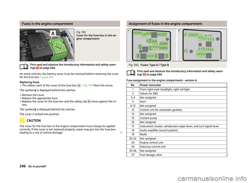
Fuses in the engine compartmentFig. 199
Cover for the fuse box in the en-
gine compartment
First read and observe the introductory information and safety warn-
ings on page 244.
On some vehicles, the battery cover must be removed before removing the cover
for the fuse box » page 216.
Replacing fuses
›
The safety catch of the cover of the fuse box
A
» Fig. 199 Move the arrow.
The symbol
is displayed behind the catches.
›
Remove the cover.
›
Replace the appropriate fuse.
›
Replace the cover on the fuse box and the safety clip
A
move against the ar-
row.
The symbol
is displayed behind the catches.
The cover is locked into position.
CAUTION
The cover for the fuse box in the engine compartment must always be applied
correctly. If the cover is not replaced properly, water may get into the fuse box -
leading to a risk of vehicle damage!
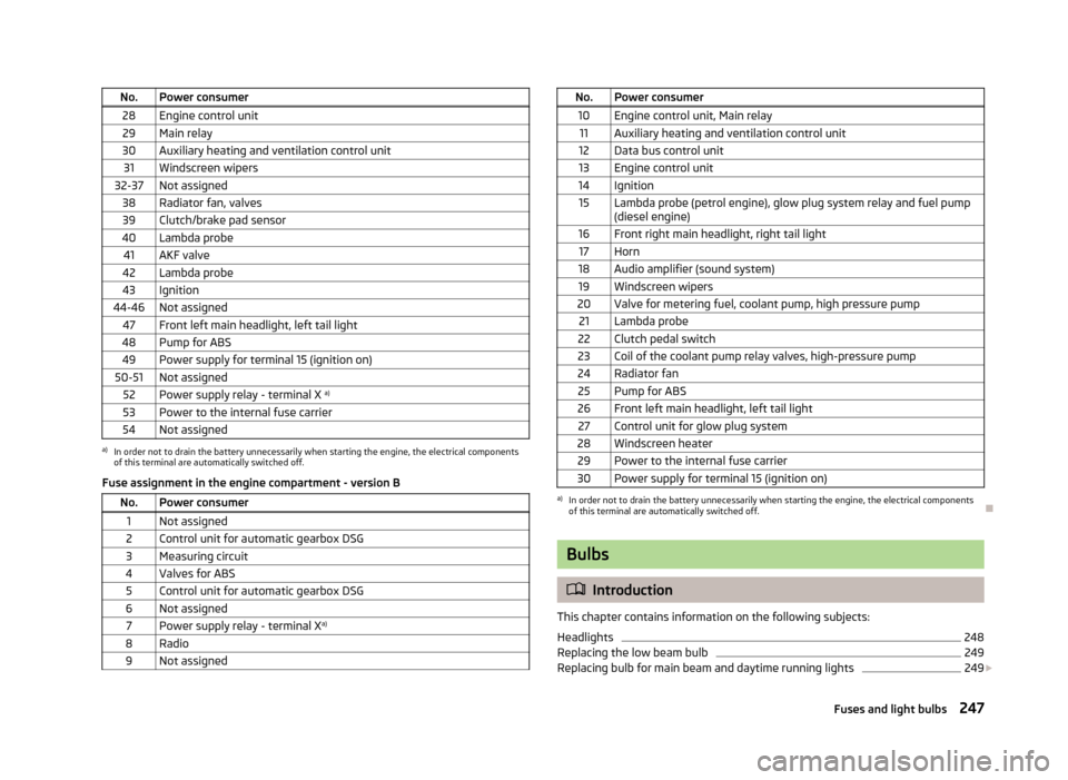
Assignment of fuses in the engine compartmentFig. 200
Fuses: Type A / Type B
First read and observe the introductory information and safety warn- ings
on page 244.
Fuse assignment in the engine compartment - version A
No.Power consumer1Front right main headlight, right tail light2Valves for ABS3-4Not assigned5Horn6-12Not assigned13Control unit for automatic gearbox14Not assigned15Coolant pump16Not assigned17Instrument cluster, windscreen wiper lever, and turn signal lever18Audio amplifier (sound system)19Radio20-22Not assigned23Engine control unit24Data bus control unit25-26Not assigned27Fuel dosage valve 246Do-it-yourself
Page 250 of 274
No.Power consumer28Engine control unit29Main relay30Auxiliary heating and ventilation control unit31Windscreen wipers32-37Not assigned38Radiator fan, valves39Clutch/brake pad sensor40Lambda probe41AKF valve42Lambda probe43Ignition44-46Not assigned47Front left main headlight, left tail light48Pump for ABS49Power supply for terminal 15 (ignition on)50-51Not assigned52Power supply relay - terminal X a)53Power to the internal fuse carrier54Not assigneda)
In order not to drain the battery unnecessarily when starting the engine, the electrical components
of this terminal are automatically switched off.
Fuse assignment in the engine compartment - version B
No.Power consumer1Not assigned2Control unit for automatic gearbox DSG3Measuring circuit4Valves for ABS5Control unit for automatic gearbox DSG6Not assigned7Power supply relay - terminal X a)8Radio9Not assignedNo.Power consumer10Engine control unit, Main relay11Auxiliary heating and ventilation control unit12Data bus control unit13Engine control unit14Ignition15Lambda probe (petrol engine), glow plug system relay and fuel pump
(diesel engine)16Front right main headlight, right tail light17Horn18Audio amplifier (sound system)19Windscreen wipers20Valve for metering fuel, coolant pump, high pressure pump21Lambda probe22Clutch pedal switch23Coil of the coolant pump relay valves, high-pressure pump24Radiator fan25Pump for ABS26Front left main headlight, left tail light27Control unit for glow plug system28Windscreen heater29Power to the internal fuse carrier30Power supply for terminal 15 (ignition on)a)
In order not to drain the battery unnecessarily when starting the engine, the electrical components
of this terminal are automatically switched off.
Bulbs
Introduction
This chapter contains information on the following subjects:
Headlights
248
Replacing the low beam bulb
249
Replacing bulb for main beam and daytime running lights
249
247Fuses and light bulbs