ESP SKODA SUPERB 2014 2.G / (B6/3T) User Guide
[x] Cancel search | Manufacturer: SKODA, Model Year: 2014, Model line: SUPERB, Model: SKODA SUPERB 2014 2.G / (B6/3T)Pages: 246, PDF Size: 17.16 MB
Page 44 of 246
Note■In certain national versions the displays appear in the Imperial system of
measures.■
If the display of the second speed is activated in mph, the current speed is
not indicated in km/h on the display.
■
The amount of fuel consumed will not be indicated.
Memory
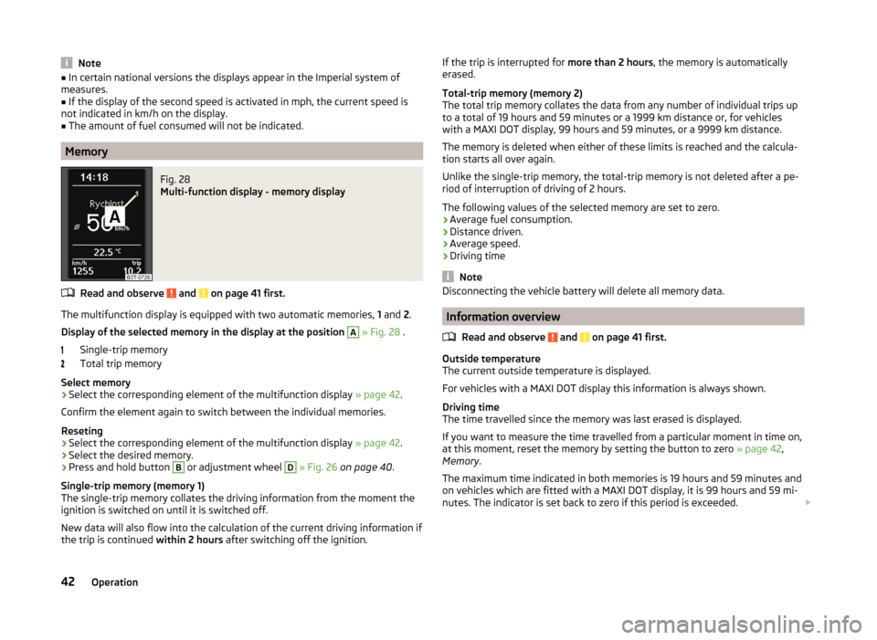
Fig. 28
Multi-function display - memory display
Read and observe and on page 41 first.
The multifunction display is equipped with two automatic memories, 1 and 2.
Display of the selected memory in the display at the position
A
» Fig. 28 .
Single-trip memory
Total trip memory
Select memory
›
Select the corresponding element of the multifunction display » page 42.
Confirm the element again to switch between the individual memories.
Reseting
›
Select the corresponding element of the multifunction display » page 42.
›
Select the desired memory.
›
Press and hold button
B
or adjustment wheel
D
» Fig. 26 on page 40 .
Single-trip memory (memory 1)
The single-trip memory collates the driving information from the moment the
ignition is switched on until it is switched off.
New data will also flow into the calculation of the current driving information if the trip is continued within 2 hours after switching off the ignition.
If the trip is interrupted for more than 2 hours, the memory is automatically
erased.
Total-trip memory (memory 2)
The total trip memory collates the data from any number of individual trips up
to a total of 19 hours and 59 minutes or a 1999 km distance or, for vehicles
with a MAXI DOT display, 99 hours and 59 minutes, or a 9999 km distance.
The memory is deleted when either of these limits is reached and the calcula-
tion starts all over again.
Unlike the single-trip memory, the total-trip memory is not deleted after a pe-
riod of interruption of driving of 2 hours.
The following values of the selected memory are set to zero.
› Average fuel consumption.
› Distance driven.
› Average speed.
› Driving time
Note
Disconnecting the vehicle battery will delete all memory data.
Information overview
Read and observe
and on page 41 first.
Outside temperature
The current outside temperature is displayed.
For vehicles with a MAXI DOT display this information is always shown.
Driving time
The time travelled since the memory was last erased is displayed.
If you want to measure the time travelled from a particular moment in time on,
at this moment, reset the memory by setting the button to zero » page 42,
Memory .
The maximum time indicated in both memories is 19 hours and 59 minutes and
on vehicles which are fitted with a MAXI DOT display, it is 99 hours and 59 mi-
nutes. The indicator is set back to zero if this period is exceeded.
42Operation
Page 55 of 246
The following applies if your vehicle has been locked using the central locking
button.
› It is not possible to open the doors or the boot lid from the outside (safety
feature, e.g. when stopping at traffic lights etc.).
› The doors can be unlocked and opened from the inside by a single pull on the
opening lever of the respective door.
› In the event of an accident in which the airbags are deployed, the locked
doors are automatically unlocked in order to enable rescuers to gain access
to the vehicle.WARNING■ Doors locked from the inside make it difficult for rescuers to get into the
vehicle in an emergency – risk to life!■
If the safelock system is switched on » page 51, the door opening lever
and the central locking buttons do not operate.
Child safety lock
Fig. 34
Parental Control: Left rear door
Read and observe on page 48 first.
The child safety lock prevents the rear door from being opened from the in- side. The door can only be opened from the outside.
You can switch the child safety lock on and off using the vehicle key.
Switching on
›
Turn the slot of the safety lock in the direction of the arrow » Fig. 34 (the
other way around on the right-hand door).
Switching off
›
Turn the slot of the safety lock in the opposite direction to the ar-
row » Fig. 34 (the other way around on the right-hand door).
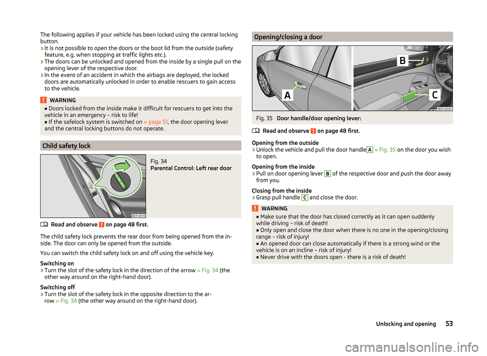
Opening/closing a doorFig. 35
Door handle/door opening lever:
Read and observe
on page 48 first.
Opening from the outside
›
Unlock the vehicle and pull the door handle
A
» Fig. 35 on the door you wish
to open.
Opening from the inside
›
Pull on door opening lever
B
of the respective door and push the door away
from you.
Closing from the inside
›
Grasp pull handle
C
and close the door.
WARNING■ Make sure that the door has closed correctly as it can open suddenly
while driving – risk of death!■
Only open and close the door when there is no one in the opening/closing
range – risk of injury!
■
An opened door can close automatically if there is a strong wind or the
vehicle is on an incline – risk of injury!
■
Never drive with the doors open - there is a risk of death!
53Unlocking and opening
Page 63 of 246
The window can be completely opened automatically by briefly pressing the
button as far as the stop. Renewed pressing of the button causes the window
to stop immediately.
Closing›
Pull gently on the top edge of the corresponding button and hold until the
window has moved into the desired position. Releasing the button causes
the window to stop immediately.
The window can also be fully closed automatically by pulling the button up to the stop. Renewed pulling of the button causes the window to stop immedi-
ately.
Safety pushbutton
The buttons for power windows in the rear doors can be deactivated by press-
ing the safety switch
S
» Fig. 43 . The buttons for the electrical power win-
dows in the rear doors are activated again by pressing the safety pushbutton
S
again.
If the buttons for the rear doors are deactivated, the indicator light in the
safety switch
S
lights up.
Opening the windows in the front passenger door and in the rear
doors
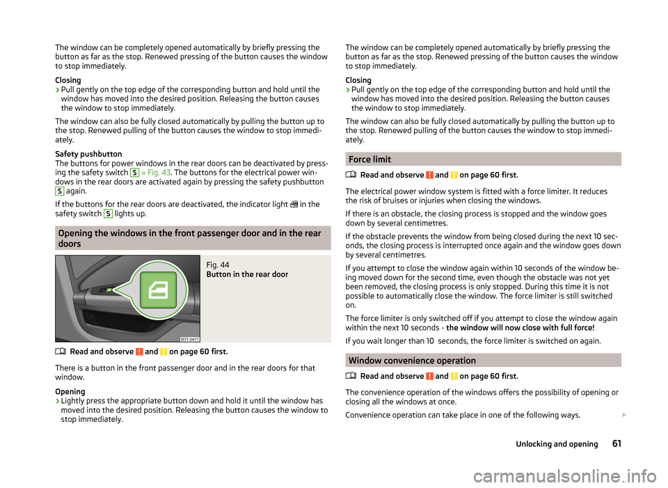
Fig. 44
Button in the rear door
Read and observe and on page 60 first.
There is a button in the front passenger door and in the rear doors for that
window.
Opening
›
Lightly press the appropriate button down and hold it until the window has
moved into the desired position. Releasing the button causes the window to
stop immediately.
The window can be completely opened automatically by briefly pressing the
button as far as the stop. Renewed pressing of the button causes the window
to stop immediately.
Closing›
Pull gently on the top edge of the corresponding button and hold until the
window has moved into the desired position. Releasing the button causes
the window to stop immediately.
The window can also be fully closed automatically by pulling the button up to the stop. Renewed pulling of the button causes the window to stop immedi-
ately.
Force limit
Read and observe
and on page 60 first.
The electrical power window system is fitted with a force limiter. It reduces
the risk of bruises or injuries when closing the windows.
If there is an obstacle, the closing process is stopped and the window goes
down by several centimetres.
If the obstacle prevents the window from being closed during the next 10 sec-
onds, the closing process is interrupted once again and the window goes down
by several centimetres.
If you attempt to close the window again within 10 seconds of the window be-
ing moved down for the second time, even though the obstacle was not yet
been removed, the closing process is only stopped. During this time it is not
possible to automatically close the window. The force limiter is still switched
on.
The force limiter is only switched off if you attempt to close the window again
within the next 10 seconds - the window will now close with full force!
If you wait longer than 10 seconds, the force limiter is switched on again.
Window convenience operation
Read and observe
and on page 60 first.
The convenience operation of the windows offers the possibility of opening orclosing all the windows at once.
Convenience operation can take place in one of the following ways.
61Unlocking and opening
Page 67 of 246
WARNINGWhen operating the sunshade, proceed with caution to avoid causing
crushing injuries – risk of injury!
Convenience operation of sliding / tilting roof
Read and observe
on page 63 first.
The sliding / tilting roof can be operated by locking or unlocking using the key
or using the KESSY system with the aid of the sensor
1
» Fig. 32 on page 50 .
Closing
›
Press and hold the symbol button on the key or hold the key in the locking
cylinder of the driver's door in the lock position, or for the KESSY system,
keep your finger on the sensor
1
» Fig. 32 on page 50 » .
By releasing the lock or lifting your finger off the sensor
1
when using the
KESSY system, the closing process is immediately interrupted.
Tilting roof
›
Press the button on the remote control key.
WARNINGClose the sliding/tilting roof carefully – risk of injury. The force limiter does
not operate with the convenience closing.Lights and visibility
Lights
Introduction
This chapter contains information on the following subjects:
Parking and low beam lights
66
Daylight running lights (DAY LIGHT)
67
Turn signal and main beam
67
Automatic driving lamp control
68
Adaptive headlights (AFS)
68
Fog lights
69
Fog lights with the CORNER function
69
Rear fog light
69
COMING HOME / LEAVING HOME
70
Hazard warning light system
70
Parking lights
71
Unless otherwise stated, the lights only work when the ignition is switched
on.
The arrangement of the controls right-hand drive models may differ from the
layout shown in » Fig. 48 on page 66 . The symbols which mark the positions
of the controls are identical.
Keep the headlights lenses clean. The following guidelines must be ob-
served » page 175 , Headlight lenses .
WARNING■
The activation of the lights should only be undertaken in accordance with
national legal requirements.■
The driver is always responsible for the correct settings and use of the
lights.
65Lights and visibility
Page 68 of 246
WARNING (Continued)■The automatic driving lamp control only operates as a support and
does not release the driver from his responsibility to check the light and, if
necessary, to switch on the light depending on the given light conditions.
The light sensor cannot, for example, detect rain or snow. Under these con-
ditions we recommend switching on the low beam or fog lights!■
Never drive with only the side lights on! The side lights are not bright
enough to light up the road sufficiently in front of you or to be seen by oth-
er oncoming traffic. Therefore always switch on the low beam when it is
dark or if visibility is poor.
Note
The headlights may mist up temporarily. When the driving lights are switched
on, the light outlet surfaces are free from mist after a short period, although
the headlight lenses may still be misted up in the peripheral areas. This mist
has no influence on the life of the lighting system.
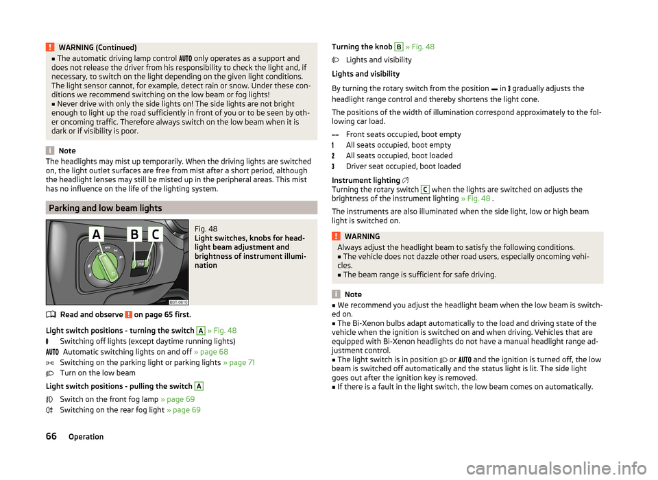
Parking and low beam lights
Fig. 48
Light switches, knobs for head-
light beam adjustment and
brightness of instrument illumi-
nation
Read and observe on page 65 first.
Light switch positions - turning the switch
A
» Fig. 48
Switching off lights (except daytime running lights) Automatic switching lights on and off » page 68
Switching on the parking light or parking lights » page 71
Turn on the low beam
Light switch positions - pulling the switch
A
Switch on the front fog lamp » page 69
Switching on the rear fog light » page 69
Turning the knob B » Fig. 48
Lights and visibility
Lights and visibility
By turning the rotary switch from the position in
gradually adjusts the
headlight range control and thereby shortens the light cone.
The positions of the width of illumination correspond approximately to the fol-
lowing car load.
Front seats occupied, boot empty
All seats occupied, boot empty
All seats occupied, boot loaded
Driver seat occupied, boot loaded
Instrument lighting
Turning the rotary switch C
when the lights are switched on adjusts the
brightness of the instrument lighting » Fig. 48 .
The instruments are also illuminated when the side light, low or high beam
light is switched on.
WARNINGAlways adjust the headlight beam to satisfy the following conditions.■The vehicle does not dazzle other road users, especially oncoming vehi-
cles.■
The beam range is sufficient for safe driving.
Note
■ We recommend you adjust the headlight beam when the low beam is switch-
ed on.■
The Bi-Xenon bulbs adapt automatically to the load and driving state of the
vehicle when the ignition is switched on and when driving. Vehicles that are
equipped with Bi-Xenon headlights do not have a manual headlight range ad-
justment control.
■
The light switch is in position
or
and the ignition is turned off, the low
beam is switched off automatically and the status light is lit. The side light
goes out after the ignition key is removed.
■
If there is a fault in the light switch, the low beam comes on automatically.
66Operation
Page 77 of 246
Retracting›Remove the sun screen from the handle A » Fig. 61 and hold it in such a way
that it can roll up slowly without being damaged.
Windscreen wipers and washers
Introduction
This chapter contains information on the following subjects:
Windscreen wipers and washers
76
Headlight cleaning system
77
The windscreen wipers and the wash system only operate if the ignition is
switched on and the bonnet is closed.
If the intermittent wipe is switched on, the intervals are also controlled de-
pending on speed.
When automatic wiping in rain is active, the wiper intervals are regulated
based on the intensity of the rain.
The rear window is wiped once automatically if the windscreen wipers are on
when reverse gear is selected.
Top up with windscreen wiper fluid » page 184.
WARNING■
Properly maintained windscreen wiper blades are essential for clear visi-
bility and safe driving » page 214.■
Replace the windscreen wiper blades once or twice a year for safety rea-
sons. These can be purchased from a ŠKODA Partner.
■
Do not use the windscreen washer system at low temperatures, without
heating the windscreen beforehand. Otherwise the window cleaner could
freeze on the windscreen and restrict the view to the front.
■
Automatic wiping in rain only operates as a support. The driver is not re-
leased from the responsibility to set the function of the windscreen wipers
manually depending on the visibility conditions.
CAUTION■ If the ignition is switched off while the windscreen wipers are switched on,
the windscreen wipers will continue wiping in the same mode after the igni-
tion is turned back on. The windscreen wipers could freeze up in cold tempera-
tures between the time the ignition was turned off and when it was turned
back on again.■
In cold temperatures and during the winter, check before the journey or be-
fore switching on the ignition that the wiper blades are not frozen to the
windscreen. If the windscreen wipers are switched on when the blades are fro-
zen to the windscreen, this may damage both the blades and windscreen wip-
er motor!
■
Carefully peel frozen wiper blades off the pane.
■
Remove snow and ice from the windscreen wipers before driving.
■
If the windscreen wipers are handled carelessly, there is a risk of damage to
the windscreen.
■
Do not switch on the ignition if the front wiper arms are retracted. The wiper
blades would move back into their rest position and while doing so damage
the paintwork of the bonnet.
■
If there is an obstacle on the windscreen, the wiper will try to push away the
obstacle. The wiper stops automatically after 5 attempts to eliminate the ob-
stacle, in order to avoid a damage to the wiper. Remove the the obstacle and
switch the wiper on again.
Note
■ Each time the ignition switches off for the third time, the position of the
windscreen wipers changes. This counteracts an early fatigue of the wiper rub-
bers.■
The rear window wiper only operates if the boot lid is closed.
■
The wiper blades should be cleaned on a regular basis with a windscreen
cleaner to avoid any smears. The wiper blades should be cleaned with a
sponge or cloth if they are heavily soiled by insect residues, for example.
■
Keep the wiper blades clean. They may become soiled, e.g., with wax resi-
dues after washing in automatic car wash systems » page 173.
■
The windscreen washer nozzles for the windscreen are heated when the en-
gine is running and the outside temperature is less than approx. +10 °C.
75Lights and visibility
Page 85 of 246
When automatic storage is activated, the current positions of the driver's seat
and the external mirrors are saved in the memory of the remote control key
each time the vehicle is locked. When the vehicle is next unlocked using the
same key, the driver's seat and the external mirrors assume the positions stor-
ed in the memory of this key 1)
.
Saving front passenger mirror settings when reversing
Above the MAXI DOT display in the menu item Mirror down. The lowering func-
tion for the mirror on the passenger side when reversing must be ena-
bled » page 45 .›
Unlock the vehicle with the remote control key.
›
Switch on the ignition.
›
Turn the knob for the external mirror control to the position for the passen-
ger side mirror adjustment » page 78.
›
Engage reverse gear.
›
Adjust the front passenger's mirror to the desired position » page 78.
›
Disengage reverse gear.
The adjusted position of the exterior mirror is stored in the remote control key
memory.
Disable the function of automatic storage
›
Unlock the vehicle with the remote control key.
›
Press and hold the SET button
A
» Fig. 70 on page 82 . At the same time,
press the button on the remote control key within 10 seconds.
The successful deactivation of the automatic storage function for each key is confirmed by an acoustic signal.
Stopping the ongoing adjustment
›
Press any button on the driver's seat or the button on the remote control
key.
Seat features
Introduction
This chapter contains information on the following subjects:
Seat heaters
83
Ventilated front seats
84Convenience features of passenger seat85Armrest, front85
Armrest rear
85
Seat backrests
85
Rear seat folded forward (Superb Combi)
86
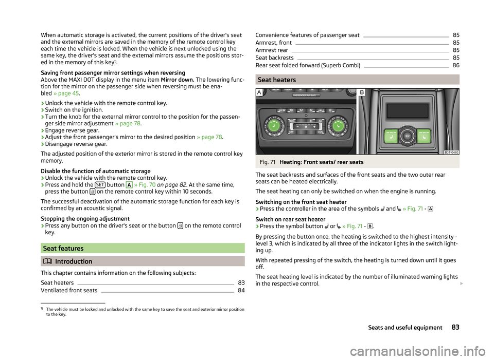
Seat heaters
Fig. 71
Heating: Front seats/ rear seats
The seat backrests and surfaces of the front seats and the two outer rear
seats can be heated electrically.
The seat heating can only be switched on when the engine is running.
Switching on the front seat heater
›
Press the controller in the area of the symbols and
» Fig. 71 -
Switch on rear seat heater
›
Press the symbol button or
» Fig. 71 -
.
By pressing the button once, the heating is switched to the highest intensity -
level 3, which is indicated by all three of the indicator lights in the switch light-
ing up.
With repeated pressing of the switch, the heating is turned down until it goes
off.
The seat heating level is indicated by the number of illuminated warning lights
in the respective control.
1)
The vehicle must be locked and unlocked with the same key to save the seat and exterior mirror position
to the key.
83Seats and useful equipment
Page 98 of 246
›Place heavy objects as far forward as possible.›Attach the items of luggage to the lashing eyes or using the
nets » page 97 .
In the event of an accident, even small and light objects gain so much kinetic
energy that they can cause severe injuries.
The magnitude of the kinetic energy is dependent on the speed at which the
vehicle is travelling and the weight of the object.
Example: In the event of a frontal collision at a speed of 50 km/h, an object
with a weight of 4.5 kg produces an energy, which corresponds to 20 times its
own weight. This means that it results in a weight of approx. 90 kg “ ”.
Luggage compartment light
The light switches on/off when the luggage compartment lid is opened or
closed.
If the boot lid is open and the ignition switched off, the light will extinguish
automatically after around 10 minutes.
Boot light for Superb Combi vehicles » page 101.WARNING■
Store the objects in the boot and attach them to the lashing eyes.■Loose objects can be thrown forward during a sudden manoeuvre or in
case of an accident and can injure the occupants or other road users.■
Loose objects could hit a deployed airbag and injure occupants – danger
of death!
■
Please note that transporting heavy objects alters the handling proper-
ties of the vehicle due to the displacement of the centre of gravity – risk of
accident! The speed and style of driving must be adjusted accordingly.
■
If the items of luggage or objects are attached to the lashing eyes with
unsuitable or damaged lashing straps, injuries can occur in the event of
braking manoeuvres or accidents. To prevent items of luggage from moving
around, always use suitable lashing straps which must be firmly attached
to the lashing eyes.
■
The transported items must be stowed in such a way that no objects are
able to slip forward on sudden driving or braking manoeuvres – risk of in-
jury!
■
When transporting objects in the luggage compartment that has been en-
larged by folding the rear seats forward, ensure the safety of the passen-
gers transported on the other rear seats » page 9.
WARNING (Continued)■
If the rear seat next to the folded forward seat is occupied, ensure maxi-
mum safety, e.g. by placing the goods to be transported in such a way that
the seat is prevented from folding back in case of a rear collision.■
Do not drive with the luggage compartment lid fully opened or slightly
ajar otherwise exhaust gases may get into the interior of the vehicle – risk
of poisoning!
■
Do not exceed the permissible axle loads and permissible gross weight of
the vehicle – risk of accident!
■
Do not transport people in the boot!
CAUTION
Make sure that transported objects with sharp edges do not damage the fol-
lowing:■
heating elements in the rear window;
■
elements of the aerial integrated in the rear window;
■
Aerial filaments integrated in the rear side windows (Superb Combi).
Note
Tyre pressure must be adjusted to the load » page 194.
Class N1 vehicles
Read and observe
and on page 96 first.
On class N1 vehicles, which are not fitted with a protective grille, a lashing set
which complies with the standard EN 12195 (1 - 4) must be used for fastening
the load.
The proper functioning of the electrical system is essential for the safe opera-
tion of the vehicle. It is important to ensure that it is not damaged during mod-
ifications or when loading or unloading the luggage compartment.
96Operation
Page 112 of 246
Operational problemsRead and observe
and on page 108 first.
If the cooling system does not operate at outside temperatures higher than +5
°C, there is a problem in the system. The reasons for this may be.
› One of the fuses has blown. Check the fuse and replace if necessa-
ry » page 215 .
› The cooling system has switched off automatically for a short time because
the coolant temperature of the engine is too hot » page 29.
If you are not able to resolve the operational problem yourself, or if the cooler
output has reduced, switch off the cooling system and seek assistance from a
specialist garage.
Air conditioning system (manual air conditioning system)
Introduction
This chapter contains information on the following subjects:
Control elements
110
adjusting
112
Recirculated air mode
112
The cooling system operates only if the following conditions are met. The cooling system is switched on » page 110.
The engine is running.
The outside temperature is above approx. +2 °C.
The blower switch is switched on (positions 1-4).
Under certain circumstances, air at a temperature of about 5 °C can flow out of
the vents when the cooling system is switched on.
If the desired interior temperature can also be achieved without activating the
cooling system, fresh air mode should be selected.
The cooling system is switched off at a high coolant temperature in order to
provide cooling at a high load of the engine.
CAUTION
Lengthy and uneven distribution of the air flow out of the vents (especially
around the feet) and large differences in temperature, for example, when get-
ting out of the vehicle, can cause susceptible individuals to catch a cold.Note■ We recommend that you have the air conditioning system cleaned by a spe-
cialist garage once every year.■
During operation of the air conditioning, an increase in engine idle speed may
occur under certain circumstances in order to ensure sufficient heating com-
fort.
Control elements
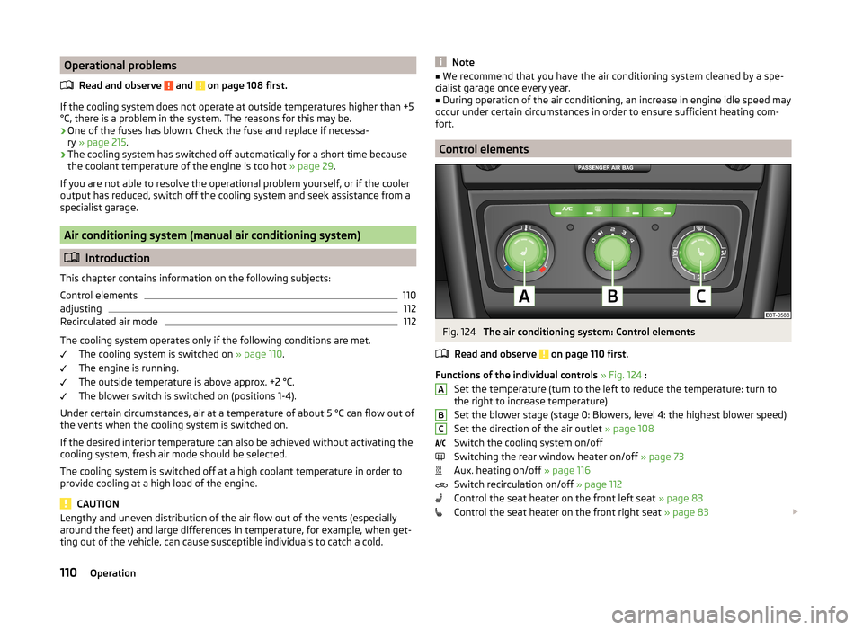
Fig. 124
The air conditioning system: Control elements
Read and observe
on page 110 first.
Functions of the individual controls » Fig. 124 :
Set the temperature (turn to the left to reduce the temperature: turn to
the right to increase temperature)
Set the blower stage (stage 0: Blowers, level 4: the highest blower speed)
Set the direction of the air outlet » page 108
Switch the cooling system on/off
Switching the rear window heater on/off » page 73
Aux. heating on/off » page 116
Switch recirculation on/off » page 112
Control the seat heater on the front left seat » page 83
Control the seat heater on the front right seat » page 83
ABC110Operation
Page 114 of 246
adjustingRead and observe
on page 110 first.
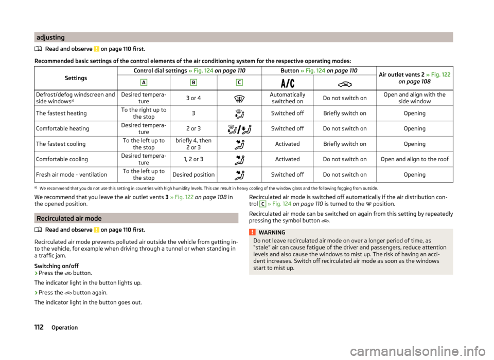
Recommended basic settings of the control elements of the air conditioning system for the respective operating modes:
SettingsControl dial settings » Fig. 124 on page 110Button » Fig. 124 on page 110Air outlet vents 2 » Fig. 122
on page 108ABCDefrost/defog windscreen and
side windows a)Desired tempera-
ture3 or 4Automaticallyswitched onDo not switch onOpen and align with the side windowThe fastest heatingTo the right up tothe stop3Switched offBriefly switch onOpeningComfortable heatingDesired tempera- ture2 or 3Switched offDo not switch onOpeningThe fastest coolingTo the left up to
the stopbriefly 4, then 2 or 3ActivatedBriefly switch onOpeningComfortable coolingDesired tempera- ture1, 2 or 3ActivatedDo not switch onOpen and align to the roofFresh air mode - ventilationTo the left up tothe stopDesired positionSwitched offDo not switch onOpeninga)
We recommend that you do not use this setting in countries with high humidity levels. This can result in heavy cooling of the window glass and the following fogging from outside.
We recommend that you leave the air outlet vents 3 » Fig. 122 on page 108 in
the opened position.
Recirculated air mode
Read and observe
on page 110 first.
Recirculated air mode prevents polluted air outside the vehicle from getting in-to the vehicle, for example when driving through a tunnel or when standing in
a traffic jam.
Switching on/off
›
Press the button.
The indicator light in the button lights up.
›
Press the button again.
The indicator light in the button goes out.
Recirculated air mode is switched off automatically if the air distribution con-
trol C » Fig. 124 on page 110 is turned to the position.
Recirculated air mode can be switched on again from this setting by repeatedly pressing the symbol button
.WARNINGDo not leave recirculated air mode on over a longer period of time, as
“stale” air can cause fatigue of the driver and passengers, reduce attention
levels and also cause the windows to mist up. The risk of having an acci-
dent increases. Switch off recirculated air mode as soon as the windows
start to mist up.112Operation