air conditioning SKODA SUPERB 2014 2.G / (B6/3T) User Guide
[x] Cancel search | Manufacturer: SKODA, Model Year: 2014, Model line: SUPERB, Model: SKODA SUPERB 2014 2.G / (B6/3T)Pages: 246, PDF Size: 17.16 MB
Page 114 of 246
adjustingRead and observe
on page 110 first.
Recommended basic settings of the control elements of the air conditioning system for the respective operating modes:
SettingsControl dial settings » Fig. 124 on page 110Button » Fig. 124 on page 110Air outlet vents 2 » Fig. 122
on page 108ABCDefrost/defog windscreen and
side windows a)Desired tempera-
ture3 or 4Automaticallyswitched onDo not switch onOpen and align with the side windowThe fastest heatingTo the right up tothe stop3Switched offBriefly switch onOpeningComfortable heatingDesired tempera- ture2 or 3Switched offDo not switch onOpeningThe fastest coolingTo the left up to
the stopbriefly 4, then 2 or 3ActivatedBriefly switch onOpeningComfortable coolingDesired tempera- ture1, 2 or 3ActivatedDo not switch onOpen and align to the roofFresh air mode - ventilationTo the left up tothe stopDesired positionSwitched offDo not switch onOpeninga)
We recommend that you do not use this setting in countries with high humidity levels. This can result in heavy cooling of the window glass and the following fogging from outside.
We recommend that you leave the air outlet vents 3 » Fig. 122 on page 108 in
the opened position.
Recirculated air mode
Read and observe
on page 110 first.
Recirculated air mode prevents polluted air outside the vehicle from getting in-to the vehicle, for example when driving through a tunnel or when standing in
a traffic jam.
Switching on/off
›
Press the button.
The indicator light in the button lights up.
›
Press the button again.
The indicator light in the button goes out.
Recirculated air mode is switched off automatically if the air distribution con-
trol C » Fig. 124 on page 110 is turned to the position.
Recirculated air mode can be switched on again from this setting by repeatedly pressing the symbol button
.WARNINGDo not leave recirculated air mode on over a longer period of time, as
“stale” air can cause fatigue of the driver and passengers, reduce attention
levels and also cause the windows to mist up. The risk of having an acci-
dent increases. Switch off recirculated air mode as soon as the windows
start to mist up.112Operation
Page 115 of 246
Climatronic (automatic air conditioning system)
Introduction
This chapter contains information on the following subjects:
Control elements
113
automatic mode
114
Switching the cooling system on/off
114
Setting the temperature
114
Recirculation mode - Version 1
115
Recirculation mode - Version 2
115
Controlling blower
116
Defrosting windscreen
116
The Climatronic in automatic mode ensures the best-possible setting of the
temperature of the outflowing air, the blower stage and air distribution.
The system also takes sunlight into account, which eliminates the need to al-
ter the settings manually.
The cooling system operates only if the following conditions are met. The cooling system is switched on » page 110.
The engine is running.
The outside temperature is above approx. +2 °C.
The cooling system is switched off at a high coolant temperature in order to
provide cooling at a high load of the engine.
Aeration of the vehicle when ignition is switched off
On models fitted with power sliding/tilting roof with sollar cells, the fresh air
blower is automatically switched over to “solar mode” if the sun ray's are suffi- cient after switching off the ignition. The solar cells on the sliding/tilting roof
deliver power for the fresh air blower. This supplies the interior of the car with
fresh air.
For an optimum ventilation, the air outlet vents 2 and 3 must be
opened » Fig. 122 on page 108 .
The ventilation functions only when the sliding/tilting roof is fully closed.
Note■ We recommend that you have Climatronic cleaned by a specialist garage
once every year.■
During operation of the Climatronic, an increase in engine idle speed can oc-
cur under certain circumstances in order to ensure adequate heating comfort.
■
On vehicles equipped with a factory-fitted radio or radio navigation system,
the Climatronic information is also shown on their displays. This function can
be switched off, see » operating instructions for the radio or navigation sys-
tem .
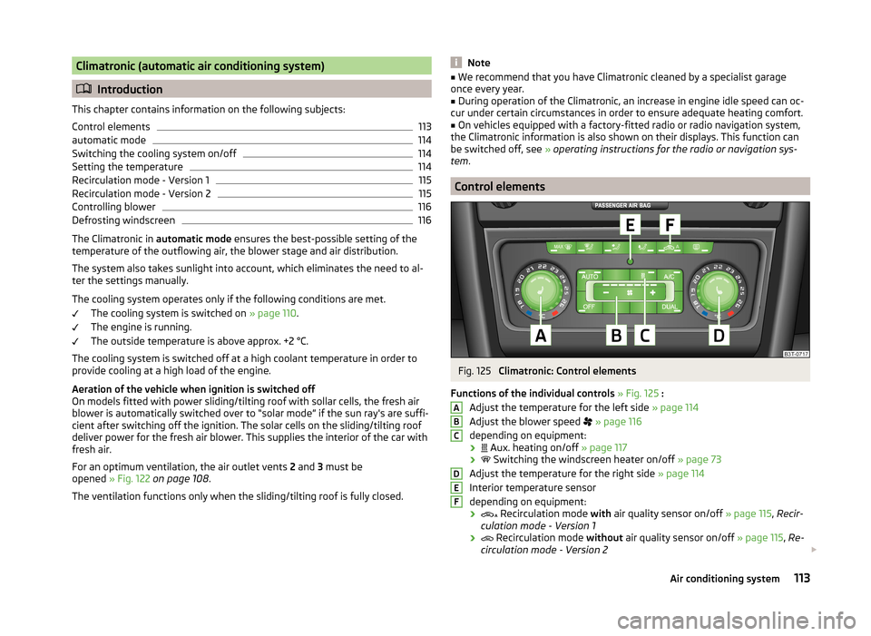
Control elements
Fig. 125
Climatronic: Control elements
Functions of the individual controls » Fig. 125 :
Adjust the temperature for the left side » page 114
Adjust the blower speed
» page 116
depending on equipment:
›
Aux. heating on/off
» page 117
›
Switching the windscreen heater on/off
» page 73
Adjust the temperature for the right side » page 114
Interior temperature sensor
depending on equipment:
›
Recirculation mode
with air quality sensor on/off » page 115, Recir-
culation mode - Version 1
›
Recirculation mode
without air quality sensor on/off » page 115, Re-
circulation mode - Version 2
ABCDEF113Air conditioning system
Page 116 of 246
Switch the intensive windscreen heater on/off
Air flow to the windows
Air flow to the upper body
Air flow in the footwell
Switching the rear window heater on/off » page 73
Control the seat heater on the front left seat » page 83
Switching automatic mode on » page 114
Switching Climatronic system off
Switch the cooling system on/off » page 114
Switch the temperature setting in Dual mode on/off » page 114
Control the seat heater on the front right seat » page 83
Note
Do not stick anything on or cover the interior temperature sensor E, other-
wise it could have an unfavourable effect on the Climatronic.
automatic mode
The automatic mode is used in order to maintain a constant temperature and
to demist the windows in the interior of the car.
Recommended setting for all periods of the year
›
Set the required temperature between +18 °C and +26 °C: we recommend 22
°C.
›
Press the
» Fig. 125 on page 113 button.
›
Set the air outlet vents 2 and 3 » Fig. 122 on page 108 so that the air flow is
directed slightly upwards.
After pressing, an indicator light in the top right or left corner of the button
lights up, depending on which mode was last selected.
If the warning light in the top right corner of the button lights up, the Cli-
matronic operates in “HIGH”-mode.
The “HIGH” mode is the standard setting of the Climatronic.
When pressing the button again, the Climatronic switches to “LOW”-mode
and the indicator light in the top left corner lights up. The Climatronic uses on-
ly in this mode the lower blower speed. However taking into account the noise
level, this is more comfortable, yet be aware that the effectiveness of the air
conditioning system is reduced particularly if the vehicle is fully occupied.
By pressing the button again, it is changed to “HIGH”-mode.
Automatic mode can be
switched off by pressing one of the buttons for the air
distribution or by increasing/decreasing the blower speed.
Switching the cooling system on/off
›
Press the button
.
The indicator light in the button lights up.
›
Press button
. once more.
The indicator light in the button goes out.
After the cooling system is switched off, only the ventilation and heating func-
tion remains active whereby the minimum temperature that can be reached is
the outside temperature.
Setting the temperature
The interior temperature for the left and right side can be set separately or to-
gether.
For both sides
›
Turn the control dial
A
» Fig. 125 on page 113 to the left or right to increase
or decrease the temperature.
The indicator light in the button lights up.
For the right side
›
Turn the control dial
D
» Fig. 125 on page 113 to the left or right to increase
or decrease the temperature.
The indicator light in the button lights up.
If the warning light in the symbol button is lit, the temperature for both
sides cannot be set with the control dial
A
. This function can be restored by
pressing the symbol button . The indicator light in the button goes out.
The interior temperature can be set between +18 °C and +26 ℃. The interior
temperature is regulated automatically within this range.
If a temperature lower than +18 °C is selected, a blue symbol lights up at the start of the numerical scale.
If a temperature higher than +26 °C is selected, a red symbol lights up at the
start of the numerical scale.
At both end positions, Climatronic functions at maximum cooling/heating out-
put and the temperature is not regulated.
114Operation
Page 117 of 246
CAUTIONLengthy and uneven distribution of the air flow out of the vents (especially
around the feet) and large differences in temperature, for example, when get-
ting out of the vehicle, can cause susceptible individuals to catch a cold.
Recirculation mode - Version 1
Recirculated air mode prevents polluted air outside the vehicle from getting in-
to the vehicle, for example when driving through a tunnel or when standing in
a traffic jam.
If a considerable increase in concentration of pollutants is recognised by the air quality sensor, recirculated air mode will temporarily be switched off.
If the concentration of pollutants decreases to the normal level, the air distri-
bution control is automatically switched off so that fresh air can be guided into
the vehicle interior.
In recirculated air mode air is sucked out of the interior of the vehicle and then
fed back into the interior.
When the automatic air distribution control is switched on, an air quality sen-
sor measures the concentration of pollutants in the drawn in air.
Switching recirculated air mode on
›
Repeatedly press the button until the indicator light on the
left side of
the button is illuminated.
Switch on automatic air distribution control
›
Repeatedly press the button until the warning light on the
right-hand
side of the button lights up.
Switch off automatic air distribution control temporarily
If the air quality sensor does not switch on automatic recirculated air mode
when there is an unpleasant smell, you can switch it on manually.
›
Press the symbol button .
The indicator light lights up in the button on the left side.
Switching recirculated air mode off
›
Press the button or press the symbol button
again until the warning
lights in the button go out.
WARNINGDo not leave recirculated air mode on over a longer period of time, as
“stale” air can cause fatigue of the driver and passengers, reduce attention
levels and also cause the windows to mist up. The risk of having an acci-
dent increases. Switch off recirculated air mode as soon as the windows
start to mist up.
Note
■ If the windscreen mists up, press the symbol button . Press the button
once the windscreen has demisted.■
The automatic air distribution control operates only if the outside tempera-
ture is higher than approx. 2 °C.
Recirculation mode - Version 2
Recirculated air mode prevents polluted air outside the vehicle from getting in-
to the vehicle, for example when driving through a tunnel or when standing in
a traffic jam.
In recirculated air mode air is sucked out of the interior of the vehicle and then
fed back into the interior.
The air recirculation mode is automatically activated after the ignition is
switched if it was on before the ignition was turned off. The indicator light in the button lights up.
Switch off / on
›
Press the
button.
The indicator light in the button goes out.
›
Press the
button again.
The indicator light in the button lights up.
WARNINGDo not leave recirculated air mode on over a longer period of time, as
“stale” air can cause fatigue of the driver and passengers, reduce attention
levels and also cause the windows to mist up. The risk of having an acci-
dent increases. Switch off recirculated air mode as soon as the windows
start to mist up. 115Air conditioning system
Page 118 of 246
NoteIf the windscreen mists up, press the symbol button . Press the button
once the windscreen has demisted.
Controlling blower
The Climatronic system controls the blower stages automatically in line with
the interior temperature.
However, the blower stages can be manually adapted to suit your particular
needs.
›
Repeatedly pressing the symbol button on the left or right reduces or in-
creases blower speed.
If the blower is switched off, the Climatronic system is switched off.
The set blower speed is displayed above the symbol button when the re-
spective number of indicator lights come on.
WARNING■ “Stale air” may result in fatigue in the driver and occupants, reduce atten-
tion levels and also cause the windows to mist up. The risk of having an ac-
cident increases.■
Do not switch off the Climatronic system for longer than necessary.
■
Switch on the Climatronic system as soon as the windows mist up.
Defrosting windscreen
Switching on
›
Press the
button » Fig. 125 on page 113 .
›
Press the
button » Fig. 125 on page 113 .
Switching off
›
Press the symbol button
again or press the symbol button
.
›
Press the symbol button
again.
More air flows out of the air outlet vents 1 » Fig. 122 on page 108 . The temper-
ature control is controlled automatically.
Auxiliary heating (auxiliary heating and ventilation)
Introduction
This chapter contains information on the following subjects:
Switching on/off
117
Radio remote control
118
Conditions for the functioning of auxiliary heating (Aux. heating and ventila-
tion), hereinafter referred to only as auxiliary heating (Aux. heating).
The charge state of the vehicle battery is sufficient.
The fuel supply is adequate (the warning icon is not lit in the display of
the instrument cluster).
Auxiliary ventilation
The auxiliary ventilation enables fresh air to flow into the vehicle interior by
switching off the engine, whereby the interior temperature is effectively de-
creased (e.g. with the vehicle parked in the sun).
Auxiliary heating (aux. heating)
The auxiliary heating (aux. heating) can be used when stationary, when the
engine is switched off to preheat the vehicle and while driving (e.g. during the
heating phase of the engine).
The auxiliary heating (auxiliary heating) functions in connection with the air-
conditioning system or Climatronic.
The auxiliary heating (aux. heating) also warms up the engine. This is not valid
for vehicles with the 3.6 l/191 kW FSI engine.
The auxiliary heating (parking heating) warms up the coolant by combusting
fuel from the vehicle tank. The coolant heats air flowing into the passenger
compartment (as long as the blower fan speed
B
» Fig. 124 on page 110
or » Fig. 125 on page 113 is not set to zero).
116Operation
Page 119 of 246
WARNING■The auxiliary heating (aux. heating) must never be operated in closed
rooms (e.g. garages) – risk of poisoning!■
The auxiliary heating (aux. heating) must not be allowed to run during re-
fuelling – risk of fire.
■
The exhaust pipe of the auxiliary heating (aux. heating) is located on the
underside of the vehicle. Therefore, if you wish to operate the auxiliary
heating (aux. heating), do not park the vehicle in such a way that the ex-
haust gases can come into contact with highly flammable materials (e.g. dry
grass) or easily inflammable substances (e.g. spilt fuel) – risk of fire.
CAUTION
■ Running auxiliary heating (aux. heating) consumes fuel from the vehicle tank
and automatically controls the filling level. If only a low quantity of fuel is
present in the fuel tank, the auxiliary heating (aux. heating) switches off.■
The exhaust pipe of the auxiliary heating (aux. heating), which is located on
the underside of the vehicle, must not be clogged and the exhaust flow must
not be blocked.
■
If the auxiliary heating (aux. heating) is running, the vehicle battery discharg-
es. If the auxiliary heating and ventilation has been operated several times
over a longer period, the vehicle must be driven a few kilometres in order to
recharge the vehicle battery.
Note
■ The auxiliary heating (aux. heating) switches on the blower B » Fig. 124 on
page 110 or » Fig. 125 on page 113 only if it has achieved a coolant temperature
of approx. 50 °C.■
At low outside temperatures, this can result in a formation of water vapour in
the area of the engine compartment. This is quite normal and is not an operat-
ing problem.
■
The air inlet in front of the windscreen must be free (e.g. of ice, snow or
leaves) to ensure that the auxiliary heating (aux. heating) operates properly.
■
So that warm air can flow into the vehicle interior after switching on the aux-
iliary heating, you must maintain the comfort temperature normally selected
by you, leave the fan switched on and leave the air outlet vents in an open po-
sition. It is recommended to put the air flow in the position
or
.
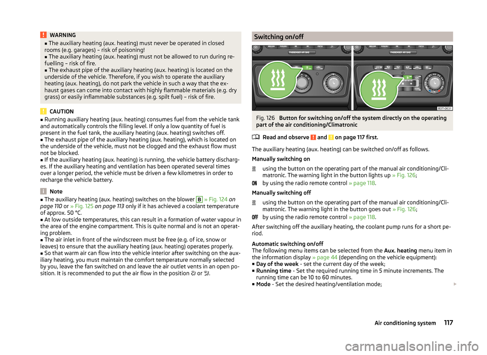
Switching on/offFig. 126
Button for switching on/off the system directly on the operating
part of the air conditioning/Climatronic
Read and observe
and on page 117 first.
The auxiliary heating (aux. heating) can be switched on/off as follows.
Manually switching on using the button on the operating part of the manual air conditioning/Cli-
matronic. The warning light in the button lights up » Fig. 126;
by using the radio remote control » page 118.
Manually switching off using the button on the operating part of the manual air conditioning/Cli-
matronic. The warning light in the button goes out » Fig. 126;
by using the radio remote control » page 118.
After switching off the auxiliary heating, the coolant pump runs for a short pe-
riod.
Automatic switching on/off
The following menu items can be selected from the Aux. heating menu item in
the information display » page 44 (depending on the vehicle equipment):
■ Day of the week - set the current day of the week;
■ Running time - Set the required running time in 5 minute increments. The
running time can be 10 to 60 minutes.
■ Mode - Set the desired heating/ventilation mode;
117Air conditioning system
Page 150 of 246
Each kilogramme of weight increases the fuel consumption. Therefore, we rec-
ommend to carry no unnecessary weight.
It is particularly in town traffic, when one is accelerating quite often, that the
vehicle weight will have a significant effect upon the fuel consumption. A rule
of thumb here is that an increase in weight of 100 kilograms will cause an in-
crease in fuel consumption of about 1 litre/100 kilometres.
At a speed of 100 - 120 km/h, a vehicle fitted with a roof rack cross member without a load will use about 10 % more fuel than normal due to the increased
aerodynamic drag.
Regular maintenance
Read and observe
on page 146 first.
A poorly tuned engine uses an unnecessarily high amount of fuel.
By having your vehicle regularly maintained by a specialist garage, you create
the conditions needed for economical driving. The maintenance state of your
vehicle has a positive effect on traffic safety and value retention
A poorly tuned engine can result in a fuel consumption which is 10 % higher than normal.
Check the oil level at regular intervals, e.g. when filling up. Oil consumption is
dependent to a considerable extent on the load and speed of the engine. Oil
consumption could be as high as 0.5 litres/1 000 km depending on your style
of driving.
It is quite normal that a new engine has a higher oil consumption at first, and
reaches its lowest level only after a certain running in time. The oil consump-
tion of a new vehicle can therefore only be correctly assessed after driving
about 5 000 km.
For the sake of the environment
■ Additional improvements to the fuel economy can be made by using synthet-
ic high-lubricity oils.■
Regularly check the ground under the vehicle. Have your vehicle inspected by
a specialist garage if you find any stains caused by oil or other fluids on the
ground.
Note
We recommend that your vehicle be serviced on a regular basis by a ŠKODA
service partner.Saving electrical energy
Read and observe
on page 146 first.
When the engine is running, the alternator generates and supplies electricalpower. If more electrical components of the electrical system are switched on,
more fuel is needed to operate the alternator. We therefore recommend
switching off electrical components if these are no longer required.
Environmental compatibility
Read and observe
on page 146 first.
Environmental protection has played a major role in the design, material selec-
tion and production of your new ŠKODA. Particular emphasis has been placed
on the following points.
Design measures › Joints designed to be easily detached.
› Simplified disassembly due to the modular structure system.
› Improved purity of different classes of materials.
› Identification of all plastic parts in accordance with VDA Recommendation
260.
› Reduced fuel consumption and exhaust emission CO
2.
› Minimum fuel leakage during accidents.
› Reduced noise.
Choice of materials
› Extensive use of recyclable material.
› Air conditioning filled with CFC-free refrigerant.
› No cadmium.
› No asbestos.
› Reduction in the “vaporisation” of plastics.
Manufacture
› Solvent-free cavity protection.
› Solvent-free protection of the vehicle for transportation from the production
plant to the customer.
› The use of solvent-free adhesives.
› No CFCs used in the production process.
› Without use of mercury.
› Use of water-soluble paints.
148Driving
Page 162 of 246
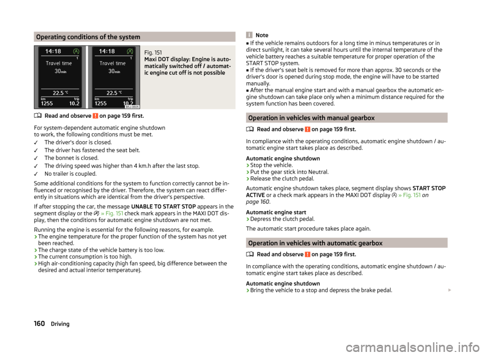
Operating conditions of the systemFig. 151
Maxi DOT display: Engine is auto-
matically switched off / automat-
ic engine cut off is not possible
Read and observe on page 159 first.
For system-dependent automatic engine shutdown
to work, the following conditions must be met.
The driver's door is closed.
The driver has fastened the seat belt.
The bonnet is closed.
The driving speed was higher than 4 km.h after the last stop.
No trailer is coupled.
Some additional conditions for the system to function correctly cannot be in-
fluenced or recognised by the driver. Therefore, the system can react differ-
ently in situations which are identical from the driver's perspective.
If after stopping the car, the message UNABLE TO START STOP appears in the
segment display or the
» Fig. 151 check mark appears in the MAXI DOT dis-
play, then the conditions for automatic engine shutdown are not met.
Running the engine is essential for the following reasons, for example.
› The engine temperature for the proper function of the system has not yet
been reached.
› The charge state of the vehicle battery is too low.
› The current consumption is too high.
› High air-conditioning capacity (high fan speed, big difference between the
desired and actual interior temperature).
Note■ If the vehicle remains outdoors for a long time in minus temperatures or in
direct sunlight, it can take several hours until the internal temperature of the
vehicle battery reaches a suitable temperature for proper operation of the
START STOP system.■
If the driver's seat belt is removed for more than approx. 30 seconds or the
driver's door is opened during stop mode, the engine will have to be started
manually.
■
After the manual engine start and with a manual gearbox the automatic en-
gine shutdown can take place only when a minimum distance required for the
system function has been covered.
Operation in vehicles with manual gearbox
Read and observe
on page 159 first.
In compliance with the operating conditions, automatic engine shutdown / au-
tomatic engine start takes place as described.
Automatic engine shutdown
›
Stop the vehicle.
›
Put the gear stick into Neutral.
›
Release the clutch pedal.
Automatic engine shutdown takes place, segment display shows START STOP
ACTIVE or a check mark appears in the MAXI DOT display
» Fig. 151 on
page 160 .
Automatic engine start
›
Depress the clutch pedal.
The automatic start procedure takes place again.
Operation in vehicles with automatic gearbox
Read and observe
on page 159 first.
In compliance with the operating conditions, automatic engine shutdown / au-
tomatic engine start takes place as described.
Automatic engine shutdown
›
Bring the vehicle to a stop and depress the brake pedal.
160Driving
Page 218 of 246
CAUTION■“Never repair” fuses or replace them with a fuse of a higher amperage – risk
of fire! This may also cause damage at another part of the electrical system.■
If a newly inserted fuse blows again after a short time, have the electrical
system checked as quickly as possible by a specialist garage.
■
A blown fuses is recognisable by the molten metal strip. Replace the faulty
fuse with a new one of the same amperage.
Note
■
We recommend always carrying replacement fuses in the vehicle. A box of
replacement fuses can be purchased from ŠKODA Original Accessories.■
There can be several power consuming devices for one fuse.
■
Multiple fuses may exist for a single power consuming device.
Fuses in the dash panel
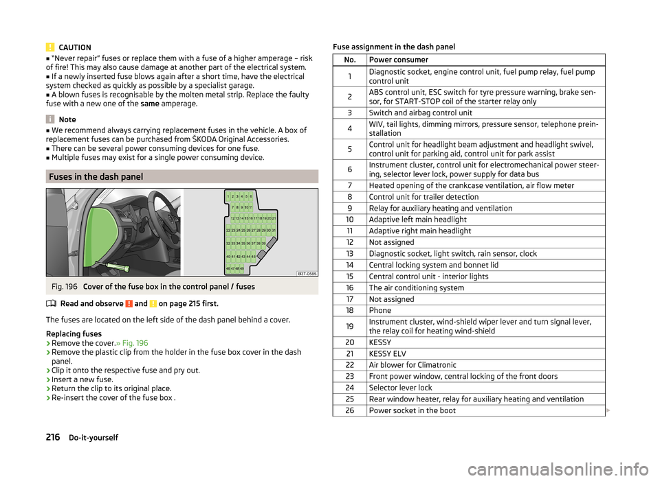
Fig. 196
Cover of the fuse box in the control panel / fuses
Read and observe
and on page 215 first.
The fuses are located on the left side of the dash panel behind a cover.
Replacing fuses
›
Remove the cover. » Fig. 196
›
Remove the plastic clip from the holder in the fuse box cover in the dash
panel.
›
Clip it onto the respective fuse and pry out.
›
Insert a new fuse.
›
Return the clip to its original place.
›
Re-insert the cover of the fuse box .
Fuse assignment in the dash panelNo.Power consumer1Diagnostic socket, engine control unit, fuel pump relay, fuel pump
control unit2ABS control unit, ESC switch for tyre pressure warning, brake sen-
sor, for START-STOP coil of the starter relay only3Switch and airbag control unit4WIV, tail lights, dimming mirrors, pressure sensor, telephone prein-
stallation5Control unit for headlight beam adjustment and headlight swivel,
control unit for parking aid, control unit for park assist6Instrument cluster, control unit for electromechanical power steer-
ing, selector lever lock, power supply for data bus7Heated opening of the crankcase ventilation, air flow meter8Control unit for trailer detection9Relay for auxiliary heating and ventilation10Adaptive left main headlight11Adaptive right main headlight12Not assigned13Diagnostic socket, light switch, rain sensor, clock14Central locking system and bonnet lid15Central control unit - interior lights16The air conditioning system17Not assigned18Phone19Instrument cluster, wind-shield wiper lever and turn signal lever,
the relay coil for heating wind-shield20KESSY21KESSY ELV22Air blower for Climatronic23Front power window, central locking of the front doors24Selector lever lock25Rear window heater, relay for auxiliary heating and ventilation26Power socket in the boot 216Do-it-yourself
Page 219 of 246
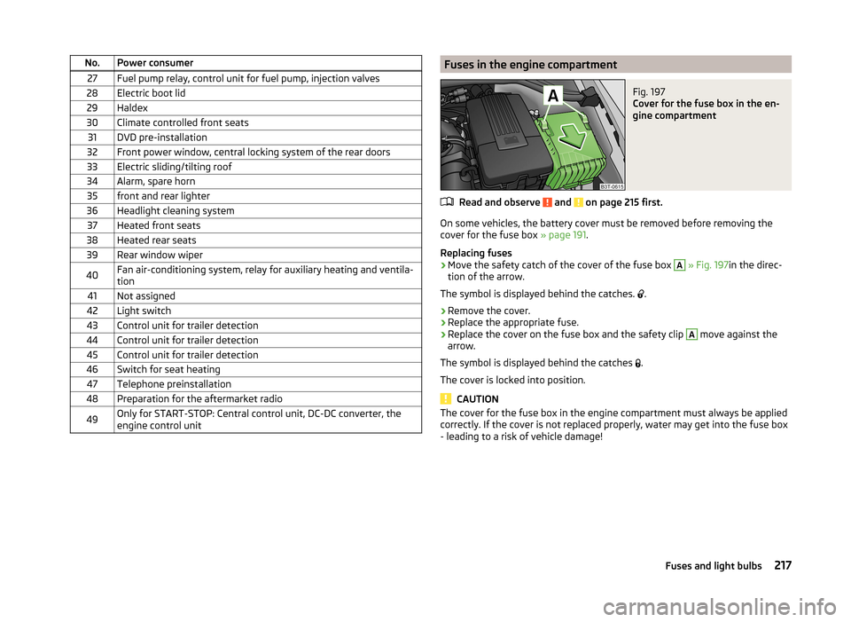
No.Power consumer27Fuel pump relay, control unit for fuel pump, injection valves28Electric boot lid29Haldex30Climate controlled front seats31DVD pre-installation32Front power window, central locking system of the rear doors33Electric sliding/tilting roof34Alarm, spare horn35front and rear lighter36Headlight cleaning system37Heated front seats38Heated rear seats39Rear window wiper40Fan air-conditioning system, relay for auxiliary heating and ventila-
tion41Not assigned42Light switch43Control unit for trailer detection44Control unit for trailer detection45Control unit for trailer detection46Switch for seat heating47Telephone preinstallation48Preparation for the aftermarket radio49Only for START-STOP: Central control unit, DC-DC converter, the
engine control unitFuses in the engine compartmentFig. 197
Cover for the fuse box in the en-
gine compartment
Read and observe and on page 215 first.
On some vehicles, the battery cover must be removed before removing the
cover for the fuse box » page 191.
Replacing fuses
›
Move the safety catch of the cover of the fuse box
A
» Fig. 197 in the direc-
tion of the arrow.
The symbol is displayed behind the catches. .
›
Remove the cover.
›
Replace the appropriate fuse.
›
Replace the cover on the fuse box and the safety clip
A
move against the
arrow.
The symbol is displayed behind the catches .
The cover is locked into position.
CAUTION
The cover for the fuse box in the engine compartment must always be applied
correctly. If the cover is not replaced properly, water may get into the fuse box
- leading to a risk of vehicle damage!217Fuses and light bulbs