air conditioning SKODA SUPERB 2014 2.G / (B6/3T) Owner's Manual
[x] Cancel search | Manufacturer: SKODA, Model Year: 2014, Model line: SUPERB, Model: SKODA SUPERB 2014 2.G / (B6/3T)Pages: 246, PDF Size: 17.16 MB
Page 5 of 246
Table of Contents
Abbreviations
Safety
Passive Safety
6
General information
6
Correct and safe seated position
7
Seat belts
10
Using seat belts
10
Inertia reels and belt tensioners
13
Airbag system
14
Description of the airbag system
14
Airbag overview
15
Deactivating airbags
19
Transporting children safely
21
Child seat
21
Fastening systems
23
Operation
Cockpit
27
Overview
26
Instruments and Indicator Lights
28
Instrument cluster
28
Warning lights
32
Information system
39
Driver information system
39
Multifunction display (MFD)
41
MAXI DOT display
44
Service interval display
46
Unlocking and opening
48
Unlocking and locking
48
Anti-theft alarm system
54
Luggage compartment lid
55Electric boot lid (Superb Combi)57Electric power windows59
Electric sliding/tilting roof
62
Panoramic sliding/tilting roof (Superb Estate)
63
Lights and visibility
65
Lights
65
Interior lights
71
Visibility
73
Windscreen wipers and washers
75
Rear mirror
77
Seats and useful equipment
79
Adjusting the seats
79
Seat features
83
Practical equipment
86
Luggage compartment
95
Removable light (Superb Combi)
101
Variable loading floor in the luggage
compartment (Estate)
102
Extending variable loading floor with
integrated aluminium rails and faseting
elements (Superb Combi)
103
Net partition (Superb Combi)
105
Roof rack system
106
Air conditioning system
108
Heating, ventilation, cooling
108
Air conditioning system (manual air
conditioning system)
110
Climatronic (automatic air conditioning
system)
113
Auxiliary heating (auxiliary heating and
ventilation)
116
Communication and multimedia
119
General information
119
Universal telephone preinstallation GSM II
122
Universal telephone preinstallation GSM IIl
124
WLAN
127Voice control129Multimedia131
Driving
Starting-off and Driving
135
Starting and stopping the engine using the key
135
Starting and stopping the engine - KESSY
137
Brakes
140
Manual gear changing and pedals
141
Automatic gearbox
142
Running in
145
Economical driving and environmental
sustainability
146
Avoiding damage to your vehicle
149
Driving abroad
150
Assist systems
151
Brake assist systems
151
Parking aid
153
Park assist
154
Cruise Control System
158
START-STOP
159
Fatigue detection (break recommendation)
162
Towing a trailer
163
Towing device
163
Trailer
166
General Maintenance
Car care
169
Services, modifications, and technical
alterations
169
Washing your car
172
Taking care of your vehicle exterior
173
Taking care of the interior
1763Table of Contents
Page 29 of 246
Operation
Cockpit
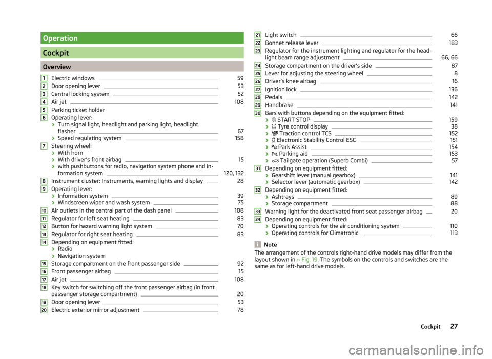
OverviewElectric windows
59
Door opening lever
53
Central locking system
52
Air jet
108
Parking ticket holder
Operating lever: › Turn signal light, headlight and parking light, headlight
flasher
67
› Speed regulating system
158
Steering wheel:
› With horn
› With driver’s front airbag
15
›with pushbuttons for radio, navigation system phone and in-
formation system
120, 132
Instrument cluster: Instruments, warning lights and display
28
Operating lever:
› Information system
39
›Windscreen wiper and wash system
75
Air outlets in the central part of the dash panel
108
Regulator for left seat heating
83
Button for hazard warning light system
70
Regulator for right seat heating
83
Depending on equipment fitted:
› Radio
› Navigation system
Storage compartment on the front passenger side
92
Front passenger airbag
15
Air jet
108
Key switch for switching off the front passenger airbag (in front
passenger storage compartment)
20
Door opening lever
53
Electric exterior mirror adjustment
781234567891011121314151617181920Light switch66
Bonnet release lever
183
Regulator for the instrument lighting and regulator for the head-
light beam range adjustment
66, 66
Storage compartment on the driver's side
87
Lever for adjusting the steering wheel
8
Driver’s knee airbag
16
Ignition lock
136
Pedals
142
Handbrake
141
Bars with buttons depending on the equipment fitted:
›
START STOP
159
›
Tyre control display
38
›
Traction control TCS
152
›
Electronic Stability Control ESC
151
›
Park Assist
154
›
Parking aid
153
›
Tailgate operation (Superb Combi)
57
Depending on equipment fitted:
› Gearshift lever (manual gearbox)
141
›Selector lever (automatic gearbox)
142
Depending on equipment fitted:
› Ashtrays
89
›Storage compartment
88
Warning light for the deactivated front seat passenger airbag
20
Depending on equipment fitted:
› Operating controls for the air conditioning system
110
›
Operating controls for Climatronic
113
Note
The arrangement of the controls right-hand drive models may differ from the
layout shown in » Fig. 19. The symbols on the controls and switches are the
same as for left-hand drive models.212223242526272829303132333427Cockpit
Page 62 of 246
WARNING■Ensure that no persons are still left in the vehicle when locking the vehi-
cle. In an emergency, the windows will no longer be able to be opened from
the inside.■
The system is fitted with a force limiter » page 61. If there is an obsta-
cle, the closing process is stopped and the window goes down by several
centimetres. However, the windows should be closed carefully – risk of in-
jury.
■
Deactivating the electrically operated power windows in the rear doors is
recommended (safety push button)
S
when children are being transported
in the rear seats » Fig. 43 on page 60 .
CAUTION
■
Keep the windows clean to ensure the correct functionality of the electric
windows.■
In the event that the windows are frozen, first of all eliminate the
ice » page 175 , Windows and exterior mirrors and only then operate the elec-
trical power windows. Otherwise, the window sealing and the electrical power
window mechanism could be damaged.
■
In the winter, ice accumulating on the surface of the window may cause
there to be more resistance when closing the window. The window will stop
and move back several centimetres.
■
It is necessary to deactivate the force limiter to close the win-
dow » page 61 .
■
Make sure that the windows are closed whenever you leave the locked vehi-
cle.
For the sake of the environment
At high speeds, you should keep the windows closed to prevent unnecessarily high fuel consumption.Note■ After switching the ignition off, it is still possible to open or close the win-
dows for approx. 10 minutes. After the driver's or front passenger's door has
been opened, the windows can only be operated by using button A
» Fig. 43
on page 60 .
■
When driving always use the existing heating, air conditioning and ventila-
tion system for ventilating the interior of the vehicle. If the windows are
opened, dust as well as other dirt can get into the vehicle and in addition the
wind noise is more at certain speeds.
■
The window lift system is equipped with protection against overheating. Re-
peated opening and closing of the window can cause this mechanism to over-
heat. If this happens, it will not be possible to operate the window for a short
time. You will be able to operate the window again as soon as the overheating
protection has cooled down.
Opening/closing the window from the driver seat
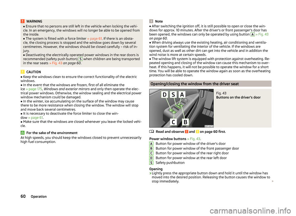
Fig. 43
Buttons on the driver's door
Read and observe and on page 60 first.
Power window buttons » Fig. 43 .
Button for power window of the driver's door
Button for power window of the front passenger door
Button for power window of the rear right door
Button for power window at the rear left door
Safety pushbutton
Opening
›
Lightly press the appropriate button down and hold it until the window has
moved into the desired position. Releasing the button causes the window to
stop immediately.
ABCDS60Operation
Page 65 of 246
Open partially›Simply turn the knob to a point between A and C.
Open fully
›
Turn the switch to position
B
and hold it in this position (spring-tensioned
position).
Tilting roof
›
Turn the switch to position
D
.
Closing
›
Turn the switch to position
A
.
Sun screen
The sun screen is also opened automatically when the tilt/slide sunroof slides
open. When the tilt/slide sunroof is closed the sun screen can be manually op-
erated »
.
Force limiter
The sliding/tilting roof is fitted with a force limiter. If an obstacle (e.g. ice) pre-
vents closing, the sliding/tilting roof stops and opens completely. The sliding/
tilting roof can be closed completely without the force limiter by pushing the
switch in position
A
» Fig. 45 forwards until the sliding/tilting roof is com-
pletely closed » .
WARNINGWhen operating the tilt/slide sunroof and the sunshade, proceed with cau-
tion to avoid causing crushing injuries – risk of injury!
CAUTION
During the winter it may be necessary to remove any ice and snow in the vicin-
ity of the sliding/tilting roof before opening it to prevent any damage to the
opening mechanism.
Convenience operation of sliding / tilting roof
Read and observe
on page 62 first.
The sliding/tilting roof can be operated by locking/unlocking using the key or
using the KESSY system with the aid of the sensor
1
» Fig. 32 on page 50 .
›
Press the
button on the remote control key.
›
In the KESSY system, hold a finger on the sensor
1
» Fig. 32 on page 50 .
By releasing the lock or lifting your finger off the sensor 1 when using the
KESSY system, the closing process is immediately interrupted.WARNINGClose the sliding/tilting roof carefully – risk of injury. The force limiter does
not operate with the convenience closing.
Electric sliding/tilting roof with solar cells
Read and observe
on page 62 first.
If there is sufficient bright sunlight, the solar cells in the sliding/tilting roof de-
liver the electrical power for the fresh air blower. Further informa-
tion » page 113 , Climatronic (automatic air conditioning system) .
The operation of the sliding/tilting roof with solar cells is the same as of a nor-
mal sliding/tilting roof.
Panoramic sliding/tilting roof (Superb Estate)
Introduction
This chapter contains information on the following subjects:
Operation
64
Opening/closing the sun screen
64
Convenience operation of sliding / tilting roof
65
The panoramic sliding/tilting roof (abbreviated in the following as 'sliding/tilt-
ing roof') can only be operated when the ignition is turned on and when the
outdoor temperature is higher than -20 °C.
The sliding/tilting roof can still be operated for approx. 10 minutes after
switching the ignition off. However, as soon as the driver or front passenger's
door is opened it is no longer possible to operate the sliding/tilting roof.
CAUTION
■ Always close the sliding/tilting roof before disconnecting the battery.■If, for example, the battery has been disconnected and reconnected, it is pos-
sible that the sliding/tilting roof does not operate correctly. Next, move the ro-
tary switch into position A
» Fig. 46 on page 64 , pull the recess firmly
63Unlocking and opening
Page 75 of 246
NoteIf the door is open and the ignition switched off, the light extinguishes auto-
matically after around 20 minutes.
Entry lighting
The lighting is positioned on the bottom edge of the exterior mirror and illumi-
nates the entry area of the front door.
The light comes on after the vehicle has been unlocked or on opening the
front door. The lighting goes out about 30 seconds after the doors are closed
or if the ignition is switched on.
WARNINGIf the entry light is on, do not touch its cover – risk of burns!
Note
If the door is open and the ignition switched off, the light will extinguish auto-
matically after around 1 minutes.
Visibility
Introduction
This chapter contains information on the following subjects:
Windscreen and rear window heater
73
Sun visors
74
Sun screen
74
Sun screen in the rear doors
74Windscreen and rear window heaterFig. 57
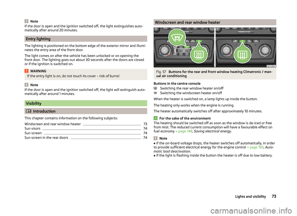
Buttons for the rear and front window heating Climatronic / man-
ual air conditioning
Buttons in the centre console Switching the rear window heater on/off
Switching the windscreen heater on/off
When the heater is switched on, a lamp lights up inside the button.
The heating only works when the engine is running.
The heater automatically switches off after approximately 10 minutes.
For the sake of the environment
The heating should be switched off as soon as the window is de-iced or free
from mist. The reduced current consumption will have a favourable effect on
fuel economy » page 148, Saving electrical energy .
Note
■
If the on-board voltage drops, the heater switches off automatically, in order
to provide sufficient electrical energy for the engine control » page 193, Auto-
matic load deactivation .■
If the light is flashing inside the button the heater is off due to low battery.
73Lights and visibility
Page 94 of 246
Storage compartment on the passenger sideFig. 90
Tray open / operating air supply
Read and observe
on page 87 first.
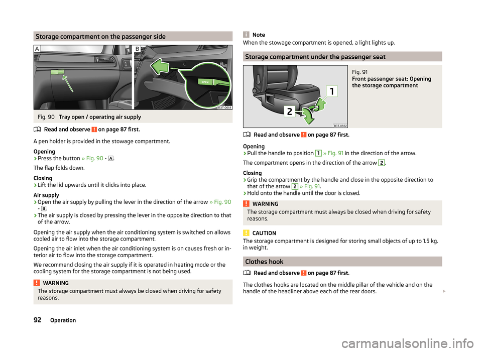
A pen holder is provided in the stowage compartment.
Opening
›
Press the button » Fig. 90 -
.
The flap folds down.
Closing
›
Lift the lid upwards until it clicks into place.
Air supply
›
Open the air supply by pulling the lever in the direction of the arrow » Fig. 90
- .
›
The air supply is closed by pressing the lever in the opposite direction to that
of the arrow.
Opening the air supply when the air conditioning system is switched on allows cooled air to flow into the storage compartment.
Opening the air inlet when the air conditioning system is on causes fresh or in-
terior air to flow into the storage compartment.
We recommend closing the air supply if it is operated in heating mode or the
cooling system for the storage compartment is not being used.
WARNINGThe storage compartment must always be closed when driving for safety
reasons.NoteWhen the stowage compartment is opened, a light lights up.
Storage compartment under the passenger seat
Fig. 91
Front passenger seat: Opening
the storage compartment
Read and observe on page 87 first.
Opening
›
Pull the handle to position
1
» Fig. 91 in the direction of the arrow.
The compartment opens in the direction of the arrow
2
.
Closing
›
Grip the compartment by the handle and close in the opposite direction to
that of the arrow
2
» Fig. 91 .
›
Hold onto the handle until the door is closed.
WARNINGThe storage compartment must always be closed when driving for safety
reasons.
CAUTION
The storage compartment is designed for storing small objects of up to 1.5 kg.
in weight.
Clothes hook
Read and observe
on page 87 first.
The clothes hooks are located on the middle pillar of the vehicle and on the
handle of the headliner above each of the rear doors.
92Operation
Page 110 of 246
Air conditioning system
Heating, ventilation, cooling
Introduction
This chapter contains information on the following subjects:
Air outlets
108
Using the air conditioning system economically
109
Operational problems
110
The heating effect is dependent upon the coolant temperature, thus full heat
output only occurs when the engine has reached its operating temperature.
If the cooling system is switched on, the temperature and air humidity drops in
the vehicle. The cooling system prevents the windows from misting up during
winter months.
It is possible to briefly activate recirculated air mode to enhance the cooling
effect.
Please refer to the information regarding recirculated air mode for the air-con-
ditioning system » page 112 or for Climatronic » page 115.
WARNINGFor your own safety and that of other road users, ensure that all the win-
dows are free of ice, snow and misting. Please familiarize yourself about
how to correctly operate the heating and ventilation systems, how to de-
mist and defrost the windows, as well as with the cooling mode.
CAUTION
■ The air inlet in front of the windscreen must be free (e.g. of ice, snow or
leaves) to ensure that the heating and cooling system operates properly.■
After switching on the cooling Condensation from the evaporator of the air
conditioning may drip down and form a puddle below the vehicle. This is not a
leak!
Note■ The exhaust air streams out through vents at the rear of the luggage com-
partment.■
We recommend that you do not smoke in the vehicle when the recirculating
air mode is operating since the smoke which is drawn at the evaporator from
the interior of the vehicle forms deposits in the evaporator of the air condition-
ing system. This produces a permanent odour when the air conditioning sys-
tem is operating which can only be eliminated through considerable effort and
expense (replacement of compressor).
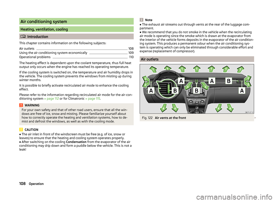
Air outlets
Fig. 122
Air vents at the front
108Operation
Page 111 of 246
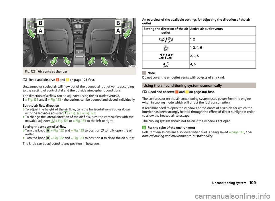
Fig. 123
Air vents at the rear
Read and observe
and on page 108 first.
Unwarmed or cooled air will flow out of the opened air outlet vents according
to the setting of control dial and the outside atmospheric conditions.
The direction of airflow can be adjusted using the air outlet vents 2,
3 » Fig. 122 and 5 » Fig. 123 - the outlets can be opened and closed individually.
Set the air flow direction
›
To adjust the height of the air flow, turn the horizontal vanes up or down
with the movable adjuster
A
» Fig. 122 » Fig. 123 .
›
To change the lateral direction of the air flow, turn the vertical fins with the
movable adjuster
A
» Fig. 122 or » Fig. 123 to the left or right.
Setting the amount of airflow
›
Turn the knob
B
» Fig. 122 and » Fig. 123 to position
to fully open the air
outlet.
›
Turn the knob
B
» Fig. 122 and » Fig. 123 to position 0 to close the air outlet.
The knob can be adjusted to any position in between.
An overview of the available settings for adjusting the direction of the air
outletSetting the direction of the air outletActive air outlet vents1, 21, 2, 4, 6 2, 3, 54, 6
Note
Do not cover the air outlet vents with objects of any kind.
Using the air conditioning system economically
Read and observe
and on page 108 first.
The compressor on the air conditioning system uses power from the engine
when in cooling mode which will effect the fuel consumption.
It recommended to open the windows or the doors of a vehicle for which the
interior has been strongly heated through the effect of direct sunlight in order
to allow the heated air to escape.
The cooling system should not be on if the windows are open.
For the sake of the environment
Pollutant emissions are also lower when fuel is being saved » page 146, Eco-
nomical driving and environmental sustainability .109Air conditioning system
Page 112 of 246
Operational problemsRead and observe
and on page 108 first.
If the cooling system does not operate at outside temperatures higher than +5
°C, there is a problem in the system. The reasons for this may be.
› One of the fuses has blown. Check the fuse and replace if necessa-
ry » page 215 .
› The cooling system has switched off automatically for a short time because
the coolant temperature of the engine is too hot » page 29.
If you are not able to resolve the operational problem yourself, or if the cooler
output has reduced, switch off the cooling system and seek assistance from a
specialist garage.
Air conditioning system (manual air conditioning system)
Introduction
This chapter contains information on the following subjects:
Control elements
110
adjusting
112
Recirculated air mode
112
The cooling system operates only if the following conditions are met. The cooling system is switched on » page 110.
The engine is running.
The outside temperature is above approx. +2 °C.
The blower switch is switched on (positions 1-4).
Under certain circumstances, air at a temperature of about 5 °C can flow out of
the vents when the cooling system is switched on.
If the desired interior temperature can also be achieved without activating the
cooling system, fresh air mode should be selected.
The cooling system is switched off at a high coolant temperature in order to
provide cooling at a high load of the engine.
CAUTION
Lengthy and uneven distribution of the air flow out of the vents (especially
around the feet) and large differences in temperature, for example, when get-
ting out of the vehicle, can cause susceptible individuals to catch a cold.Note■ We recommend that you have the air conditioning system cleaned by a spe-
cialist garage once every year.■
During operation of the air conditioning, an increase in engine idle speed may
occur under certain circumstances in order to ensure sufficient heating com-
fort.
Control elements
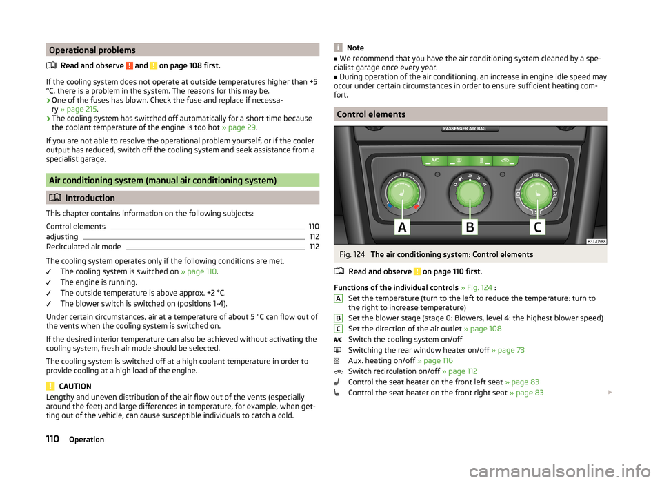
Fig. 124
The air conditioning system: Control elements
Read and observe
on page 110 first.
Functions of the individual controls » Fig. 124 :
Set the temperature (turn to the left to reduce the temperature: turn to
the right to increase temperature)
Set the blower stage (stage 0: Blowers, level 4: the highest blower speed)
Set the direction of the air outlet » page 108
Switch the cooling system on/off
Switching the rear window heater on/off » page 73
Aux. heating on/off » page 116
Switch recirculation on/off » page 112
Control the seat heater on the front left seat » page 83
Control the seat heater on the front right seat » page 83
ABC110Operation
Page 113 of 246
NoteThe warning light in the symbol button lights after activation, even if not all
of the conditions for the function of the cooling system are met » page 110. By
lighting up of the indicator light in the button, the operational readiness of the
cooling system is signalled.111Air conditioning system